1. Introduction
Omnidirectional mobile platforms are increasingly used in indoor service, logistics, rehabilitation, and human-assistance applications because they can translate laterally, move diagonally, and rotate in place within confined spaces. Among common wheeled mobile robot architectures, the four-Mecanum-wheel chassis is attractive because it provides holonomic planar motion with relatively simple mechanical construction and compact footprint [
1]. This capability is useful for companion transport in hospitals and rehabilitation centers, shelf-to-shelf handling in warehouses and laboratories, and service robots operating in exhibition halls, airports, and hotels. Recent work on assistive mobility also shows that Mecanum and omni-wheel technologies are promising for maneuvering in constrained environments, although stability, control complexity, uneven-ground robustness, and cost remain major challenges [
2]. Clinical and rehabilitation-oriented systems using Mecanum wheels further illustrate the potential of omnidirectional platforms for over-ground walking assistance [
3].
For mobile robots that operate near humans, following control can be realized through multiple sensing and interaction modalities. High-level perception methods, such as visual tracking, LiDAR-based target detection, SLAM, and UWB localization, can estimate human–robot relative pose without physical contact. However, they require sufficiently observable environments, reliable target association, and sometimes expensive or infrastructure-dependent sensors. Camera-based systems are sensitive to lighting variation, occlusion, and clutter; LiDAR and SLAM systems can fail in geometrically repetitive or texture-poor indoor corridors; and UWB systems require anchors or tags that may not be convenient in temporary deployments. These limitations are not fatal for autonomous navigation, but they become important when the engineering objective is a low-cost, low-perception-dependence companion platform that can be deployed quickly and guided naturally by a nearby user.
Physical human–robot interaction (pHRI) provides an alternative route. Instead of inferring human intent from remote perception, the robot can sense physical input applied by the user and transform it into motion commands. Force-guided mobile platforms and compliant-arm systems have shown that direct physical guidance can be an intuitive way to command robot motion [
4]. More general pHRI control research also emphasizes the importance of mapping measured forces or motions to stable robot motion through impedance or admittance principles [
5]. For a companion cart or indoor handling platform, a user often does not need a fully autonomous follower; the practical requirement is that the platform should move in the intended direction with low cognitive load, moderate compliance, and predictable behavior. A rope-tensioned interaction structure can satisfy this requirement while avoiding the need for high-level external perception.
Mecanum-wheel platforms also present a specific localization problem. Although the drive wheels are equipped with encoders, the relationship between wheel rotation and platform displacement is affected by roller contact state, load distribution, acceleration, floor friction, and instantaneous slip. Pose estimation based only on drive-wheel odometry can therefore accumulate errors during acceleration, emergency stops, lateral motion, and diagonal motion. Recent studies on Mecanum platforms have addressed pose estimation and control using EKF-based sensor fusion [
6], unknown input and uncertainty estimation [
7], disturbance-observer-enhanced control [
8], command-to-motion modeling [
9], and intelligent path planning or fuzzy control [
10]. These methods improve different layers of the Mecanum platform performance, but a mechanically independent displacement measurement source remains valuable when drive-wheel slip contaminates odometry.
Orthogonal passive-wheel odometry provides such an independent measurement source. Orthogonal odometers use passive wheels arranged along perpendicular axes to directly measure planar displacement with encoders. Because these wheels are not used for propulsion, their encoder readings are less coupled to drive torque, roller slip, and motor transients. Previous work on orthogonal wheel odometers demonstrated that such systems can achieve centimeter-level positioning in relative coordinate frames and can reduce the effect of wheel slip and ground irregularity by using driven or passive sensing structures [
11]. Related Chinese theses and engineering studies on inertial-sensor and orthogonal odometry planar localization further show the feasibility of combining MEMS attitude estimation, encoder odometry, coordinate transformation, and software compensation for indoor robot positioning [
12,
13]. Multi-sensor fusion and robust control studies also support the idea that improved localization quality directly benefits following and formation control performance [
14].
To make the positioning of the work clearer, the related systems can be viewed along two complementary axes: the interaction interface used to infer the operator’s intention and the localization method used to estimate the motion of the mobile base. Vision-, LiDAR-, and UWB-based following methods emphasize remote perception but depend on environmental observability or external infrastructure. Force-guided handles and admittance-controlled platforms provide direct physical interaction, but they usually require calibrated force sensing or compliant arms. Conventional Mecanum platforms provide omnidirectional mobility, but their drive-wheel odometry is sensitive to roller-ground contact and slip. The present study addresses the intersection of these issues by combining a rope-tensioned gimbal posture interface with an independent orthogonal passive-wheel odometry module.
Accordingly, the novelty of the proposed system lies not in the Mecanum-wheel chassis alone, but in the complete low-perception-dependence following chain: physical traction intention is converted into pitch and roll posture, the posture signal is mapped into bounded planar velocity commands, and the realized motion is corrected using odometry that is mechanically decoupled from the drive wheels. This design reduces dependence on ambient perception and mitigates the localization error that would otherwise arise from Mecanum-wheel slip.
This paper builds on these ideas but addresses a different problem: passive following of a Mecanum-wheel platform through a low-perception-dependence physical interaction interface. The proposed system combines a rope-tensioned gimbal for intention perception with orthogonal passive-wheel odometry for planar pose feedback. The gimbal translates the user’s pulling direction and intensity into pitch and roll changes, while the orthogonal odometry module provides real-time planar displacement feedback independent of the Mecanum drive wheels. MEMS attitude estimation, gyroscope drift compensation, and filtering are used to stabilize the posture signal, drawing on established inertial measurement and signal processing techniques [
15,
16,
17].
Broader person-following studies further clarify the research gap addressed here. Comprehensive reviews classify person-following robots by perception modality, interaction mode, and autonomy level [
18]. Camera- and laser-based systems demonstrate the remote-perception route [
19,
20], whereas deep visual tracking, UWB following, and robust image-based tracking remain dependent on reliable sensing, target association, or infrastructure [
21,
22,
23]. Reviews of autonomous mobile robots and sensor fusion challenges identify localization robustness as a persistent limitation [
24], and Mecanum-specific drift compensation studies show that omnidirectional bases require explicit treatment of slip, sensor bias, and drift [
25]. These studies indicate that a low-perception-dependence physical interface combined with mechanically independent odometry can reduce limitations of perception dependence and drive-wheel slip.
The main contributions of this paper are as follows:
A passive following interaction method is proposed based on rope-tensioned gimbal posture perception. The method uses pitch and roll angle changes in a gimbal-mounted six-axis IMU to infer the user’s traction intention without relying on vision, LiDAR, or other high-level environmental perception.
A posture-to-velocity mapping model is constructed for natural interaction control. The model maps gimbal pitch and roll angles to forward-backward and lateral velocity commands, respectively, and incorporates dead-zone suppression, velocity saturation, low-pass filtering, and acceleration limiting.
Orthogonal passive-wheel odometry is fused with inertial attitude estimation to construct a planar localization feedback loop for the Mecanum-wheel platform. The scheme reduces the influence of drive-wheel slip and discontinuous Mecanum roller-ground contact on pose estimation.
A prototype system is implemented and experimentally evaluated. Attitude estimation, localization accuracy, passive following, gyroscope compensation, orthogonal odometry, and closed-loop feedback are quantitatively compared.
The remainder of this paper is organized as follows.
Section 2 describes the system architecture, mechanical design, hardware implementation, coordinate systems, posture-to-velocity mapping, attitude estimation, orthogonal odometry, and experimental protocol.
Section 3 reports the experimental results.
Section 4 discusses the significance, engineering applicability, and limitations of the system.
Section 5 concludes the paper and presents future work.
2. Materials and Methods
2.1. Overall System Architecture
As shown in
Figure 1, the proposed passive following system is organized as a four-layer architecture: mechanical platform, perception, computation, and control. The mechanical platform layer consists of a four-Mecanum-wheel chassis, a rope-tensioned two-axis gimbal, and an orthogonal passive-wheel odometry module. The perception layer includes the gimbal-mounted six-axis IMU, a chassis attitude sensor, magnetic encoders on the orthogonal passive wheels, and an embedded display interface. The computation layer performs inertial data preprocessing, attitude estimation, gyroscope error compensation, posture-to-velocity mapping, orthogonal odometry calculation, coordinate transformation, and feedback correction. The control layer generates motor commands for omnidirectional motion and updates the display interface.
During operation, the user pulls the rope attached to the gimbal. The gimbal deflects about its pitch and roll axes, while yaw is constrained by the mechanical structure. The top-mounted IMU measures the resulting posture changes. The system maps the measured pitch and roll angles to target velocities in the vehicle coordinate frame. At the same time, orthogonal passive wheels measure platform displacement increments, and inertial attitude estimation provides heading information. The platform’s planar pose in the navigation coordinate frame is recursively estimated and used to correct the following motion. The complete control chain is therefore:
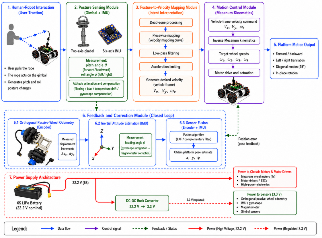
Figure 2 organizes the system into seven numbered modules. Modules 1–5 show the main operation sequence. User traction acts on the rope and gimbal, and the six-axis IMU measures pitch and roll posture. The posture-to-velocity mapping module then applies dead-zone processing, piecewise mapping, low-pass filtering, and acceleration limiting. The Mecanum kinematics module converts the vehicle-frame command Vx, Vy, and omega_z into target wheel speeds for platform motion.
Module 6 shows the closed-loop feedback path. Orthogonal passive-wheel odometry supplies encoder-based displacement increments, inertial attitude estimation supplies the heading angle psi, and sensor fusion estimates x, y, and psi. The resulting pose feedback is returned to the motion-control module as a position-error correction signal.
The power-supply architecture is shown as Module 7. A 6S LiPo battery (22.2 V nominal, 25.2 V fully charged) directly supplies the chassis motors and motor drivers through the high-voltage power path. A DC-DC buck converter steps 22.2 V down to a regulated 3.3 V for low-power sensors, including the orthogonal passive-wheel odometry encoders, IMU/gyroscope, magnetometer, and gimbal sensors. Solid red arrows denote the high-voltage path, whereas dashed red arrows denote the regulated 3.3 V path.
2.2. Mechanical Design
2.2.1. Mecanum-Wheel Chassis
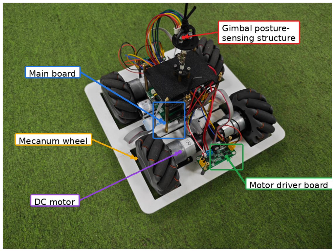
The prototype uses a compact four-wheel independent-drive Mecanum chassis with approximate dimensions of 300 mm × 300 mm × 150 mm. Four Mecanum wheels are symmetrically arranged in a rectangular layout. By controlling the speed and direction of the four wheels, the platform can perform forward-backward translation, lateral translation, diagonal motion, and in-place rotation. This motion capability is well-suited to narrow indoor environments, where the platform may need to follow a user through corridors, around shelves, or beside beds and instruments.
The rectangular 300 mm × 300 mm layout was selected to keep the prototype compact while preserving symmetric wheel spacing for forward-backward, lateral, diagonal, and in-place rotational motion. This geometry is functional for indoor operation because the platform can translate laterally in narrow passages without first rotating its body. Compared with general all-directional platforms such as modular Mecanum research bases, the present platform is optimized for rope-guided passive following rather than autonomous navigation or payload-agnostic service operation. The rectangular form is therefore suitable for the current proof-of-concept, although rounded or protected outer packaging would be preferable for crowded clinical, hotel, or exhibition environments.
The same mechanical feature that enables omnidirectional motion also affects odometry reliability. Mecanum wheels generate lateral components through passive rollers. Their contact state depends on load distribution, roller position, floor material, and acceleration profile. During rapid starts, stops, or diagonal motion, wheel-ground slip and roller contact discontinuity can cause drive-wheel encoder odometry to deviate from actual chassis displacement. This motivates the addition of orthogonal passive-wheel odometry as an independent planar displacement source.
2.2.2. Gimbal-Rope Interaction Mechanism
The gimbal-rope interaction mechanism is the main human–robot interface of the system. A two-axis orthogonal gimbal is mounted above the chassis. A rope is connected to the upper end of the gimbal, and a six-axis IMU is rigidly fixed near the top of the gimbal. When a user pulls the rope, the gimbal rotates about pitch and roll axes. The pitch angle represents the forward-backward component of the traction intention, while the roll angle represents the lateral component. The yaw angle is mechanically constrained and is not used as the primary intention signal.
The gimbal is used as a lead-input device rather than as a sensor for autonomous target tracking. A forward or backward traction component mainly changes the pitch angle, whereas a lateral traction component mainly changes the roll angle. When the pulling direction is oblique, both axes are excited, and the controller generates combined longitudinal and lateral velocity commands. The control axes are equipped with the gimbal-mounted six-axis IMU; the orthogonal odometry axes are equipped with magnetic encoders on the passive wheels.
The prototype does not impose a single fixed rope-tension threshold for operation. Instead, the motion command is triggered by posture deflection after the dead-zone threshold is exceeded. The force required to produce this deflection depends on rope length, rope attachment height, gimbal stiffness, user height, and pulling posture. Therefore, we clarify that the present implementation is posture-threshold operated rather than force-threshold operated, and future work should identify adaptive calibration parameters for different users and rope configurations.
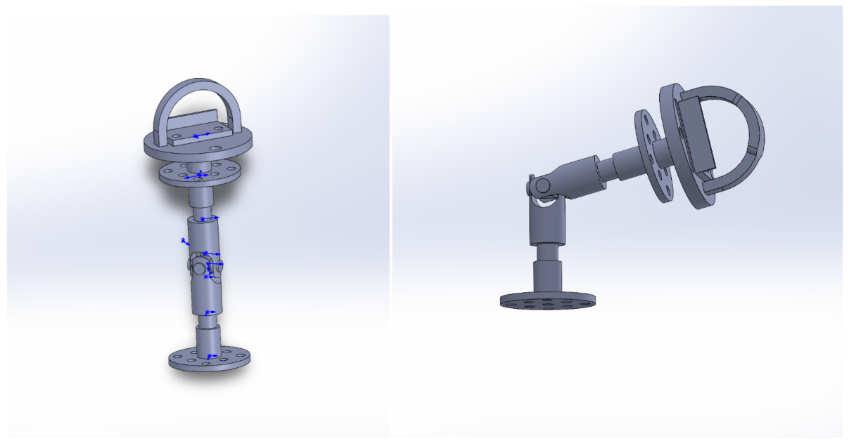
As shown in
Figure 3, the left model represents the neutral configuration without traction, whereas the right model illustrates the deflected configuration when the user pulls the rope. The deflection is measured as pitch and roll changes and is used as the input for platform motion control.
Compared with button-based or joystick-based operation, the gimbal-rope interface preserves the physical intuition of pulling a cart. Compared with force sensors installed in handles, the proposed structure uses posture perception rather than direct force measurement, reducing sensing complexity. The interaction signal is also independent of ambient lighting and environmental geometry, which is useful in low-perception-dependence applications.
In
Figure 3, the upper ring provides the rope attachment point, the middle joint allows two-axis angular deflection, and the lower mounting flange fixes the mechanism to the mobile platform. The IMU is mounted close to the top structure so that the measured pitch and roll angles represent the user-applied traction direction.
2.2.3. Orthogonal Passive-Wheel Odometry Module
The orthogonal odometry module uses two passive omnidirectional wheels installed under the chassis. Their measurement axes are aligned with the vehicle coordinate axes. Each passive wheel is coupled with a magnetic encoder to measure wheel rotation. Because the wheels are passive and are not driven by motors, their measurements are less affected by the drive torque and slip of the Mecanum wheels.
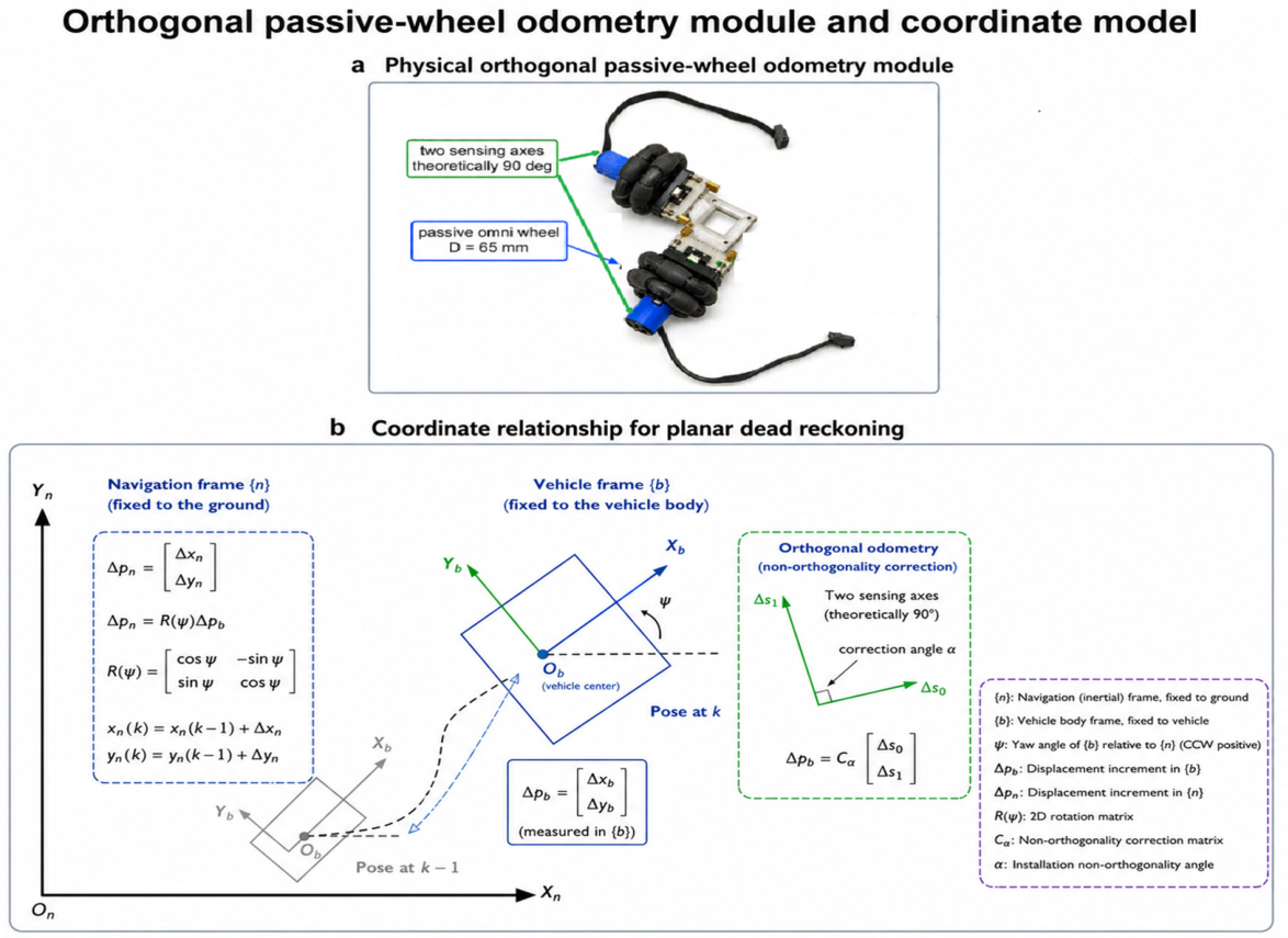
The geometry of this wheel section is functional. The two non-driven passive omnidirectional wheels are used only for displacement sensing, not for propulsion. Each passive wheel has a diameter of 65 mm (radius of 32.5 mm), and the two sensing axes are theoretically arranged at an included angle of 90 degrees. This orthogonal arrangement separates longitudinal and lateral displacement increments in the vehicle frame. It also reduces the influence of the Mecanum drive torque, roller contact discontinuity, and wheel slip on the odometry measurement.
Let the two passive-wheel radii be and , and let the encoder pulse increments during one sampling interval be and . If the encoder resolution is pulses per revolution, the displacement increments measured by the two passive wheels are:
Here, R
0 and R
1 denote the radii of the two passive odometry wheels, Δenc0 and Δenc1 are the encoder count increments over one sampling interval, N is the encoder resolution in pulses per revolution, and Δs
0 and Δs
1 are the corresponding wheel displacement increments. The vector
represents the planar displacement increment in the vehicle frame. The calibration matrix Cα compensates for the measured non-orthogonality angle α between the two passive-wheel measurement axes.
Ideally,
and
correspond to the lateral and longitudinal displacement increments in the vehicle frame. If installation non-orthogonality exists, an auxiliary odometry coordinate frame is used for calibration. For a small non-orthogonal deviation
, the corrected vehicle-frame displacement increment can be expressed as:
where
is the calibration matrix determined from the measured installation angle and distance calibration experiments.
2.3. Hardware Platform and Embedded Implementation
2.3.1. Main Controller, Power Supply, and Motor Drive
The embedded control system uses an Infineon TRAVEO CYT4BB77 microcontroller with Arm Cortex-M4 and Cortex-M0+ cores and a maximum operating frequency of 350 MHz. The controller executes multi-task processing for sensor acquisition, attitude estimation, planar localization, velocity mapping, and closed-loop motor control. The prototype is powered by a 6S lithium battery pack with a nominal voltage of 22.2 V and a full-charge voltage of 25.2 V. As shown in
Figure 2, the 6S LiPo battery supplies the motor drivers and chassis motors through the 22.2 V high-voltage path. A DC-DC buck converter provides regulated 3.3 V power for the orthogonal passive-wheel odometry encoders, IMU/gyroscope, magnetometer, and gimbal sensors.
The motor drive uses TI DRV8701E H-bridge gate drivers for DC brushed motors. The DRV8701E supports 100% duty-cycle operation and can be controlled through PWM and direction logic. Four independent drive circuits are used for the four Mecanum wheels. Current sensing and overcurrent protection are included to improve safety during start-up, emergency stops, and high-load following.
2.3.2. Attitude Sensing and Human–Machine Interface
The attitude sensing module uses Bosch BMI270 and STMicroelectronics LSM6DSRTR six-axis IMUs. The BMI270 provides gyroscope and accelerometer data suitable for motion-state perception. The LSM6DSRTR provides low-noise inertial data for stable attitude estimation. Both sensors communicate with the main controller through standard embedded interfaces. The platform also includes an IPS200 or serial display interface for showing heading, planar coordinates, gimbal posture, velocity commands, and operating mode.
2.3.3. Software Architecture
The software follows a layered data-flow architecture:
Sensor acquisition: reads IMU data and encoder pulse increments.
Error compensation: performs zero-bias compensation, noise filtering, temperature-drift compensation, and static-state suppression.
Attitude estimation: updates the quaternion attitude and converts it to Euler angles.
Coordinate calculation: estimates planar displacement and heading in the navigation coordinate frame.
Velocity mapping: converts gimbal posture to target chassis velocity.
Motion control: generates wheel velocity commands and feedback correction.
Display and parameter interface: shows system status and allows parameter adjustment.
This modular structure separates low-level sensor handling from high-level following control. It also allows the same platform to switch between fixed-point planar motion and gimbal-based passive following.
2.4. Coordinate Frames and Kinematic Modeling
Four coordinate frames are defined:
Navigation frame : a fixed East-North-Up reference frame. The initial platform position is defined as the origin.
Vehicle frame : a body-fixed frame whose origin is located at the geometric center of the chassis. The axis points to the right side of the chassis, the axis points forward, and the axis points upward.
Gimbal frame : a frame fixed to the gimbal top. Pitch and roll relative to the vehicle frame represent traction intention.
Odometry frame : a planar frame associated with the orthogonal passive wheels.
Figure 4 contains a physical view of the orthogonal passive-wheel odometry module and a coordinate schematic for planar dead reckoning. The two passive omni wheels have a diameter of 65 mm and are theoretically mounted with a 90-degree included angle, so the two wheels measure two vehicle-frame displacement components. Magnetic encoders measure the rotation of the passive wheels. Any small installation non-orthogonality is represented by alpha and compensated by the calibration matrix
before the vehicle-frame displacement increment is rotated into the navigation frame by the heading angle psi.
After orthogonal odometry provides the vehicle-frame displacement increment
, the navigation-frame displacement increment is calculated using the platform heading
:
The planar position is then recursively updated:
The inverse kinematics of a four-Mecanum-wheel chassis can be written in the general form:
where
is the Mecanum-wheel radius,
is the four-wheel angular velocity vector,
are vehicle-frame translational velocities,
is the yaw angular velocity, and
is determined by the wheel arrangement and chassis geometry. In this study, the following system focuses on generating
and
from the gimbal posture, while
is controlled by the platform heading and task mode.
2.5. Posture-to-Velocity Mapping
The gimbal pitch angle is mapped to the forward-backward velocity command , and the roll angle is mapped to the lateral velocity command . The mapping is designed to be sensitive near intentional pulling, stable near zero, and bounded at high deflection angles.
The roll-axis mapping uses the same form:
The implemented parameters are
deg,
mm/s/deg,
deg, and
mm/s. A first-order low-pass filter is applied to suppress sudden velocity jumps:
where
s. In addition, acceleration limiting constrains the velocity command variation per control cycle:
The final target velocity is:
This mapping transforms the user’s continuous traction action into smooth omnidirectional motion commands.
The mapping process can be interpreted as five sequential steps. First, small deflections within the dead zone are ignored to prevent unintended motion. Second, the effective pitch and roll deflections beyond the dead zone are converted into longitudinal and lateral velocity components through a linear gain. Third, the raw velocity command is bounded by the software command limit. Fourth, the command is smoothed using a first-order low-pass filter. Fifth, the velocity variation between consecutive control cycles is constrained by acceleration limiting.
It should be noted that the velocity generated by the linear posture-to-velocity mapping and the final software command limit are two different quantities. With the implemented parameters, namely θdead = ϕdead = 2 deg, and , the maximum value generated by the linear branch at the saturation angle is 15 × (15 − 2) = 195 mm/s. Therefore, vxmax = vymax = 500 mm/s denotes the upper software limit applied to the final velocity command, rather than the velocity value generated exactly at theta_sat = 15 deg.
The 600 mm/s condition used in the traction-speed tests refers to the externally imposed traction-speed level over the 5000 mm test path. It is not the platform velocity command limit. Thus, the 600 mm/s traction-speed condition and the 500 mm/s platform command limit represent two different physical quantities.
2.6. Attitude Estimation and Gyroscope Error Compensation
The gimbal attitude is estimated from gyroscope and accelerometer data. Quaternion representation is used to avoid singularities associated with Euler-angle integration. Let the quaternion be:
The quaternion derivative driven by angular velocity
is:
where
The quaternion is updated numerically and normalized at each cycle. Euler angles are then obtained for the posture-to-velocity mapping. To improve long-term stability, the following compensation steps are applied:
Static zero-bias compensation for gyroscope output.
Kalman filtering or complementary filtering for noise suppression.
Temperature drift compensation using calibration data.
Static-state thresholding to suppress small residual angular velocity accumulation.
The system compares gradient-descent attitude estimation and Mahony complementary filtering. The final compensated scheme combines filtering, temperature drift compensation, and constant zero-bias compensation.
2.7. Closed-Loop Passive Following Control
The following two modes are considered. Mode A is an open-loop attitude following: the platform receives velocity commands generated only from the gimbal posture mapping. Mode B is closed-loop following: the platform uses orthogonal odometry localization feedback to correct accumulated displacement and reduce path deviation.
Let
be the desired endpoint or trajectory state inferred from the traction command and
be the estimated platform position from orthogonal odometry. A simple feedback correction can be written as:
where
is the planar correction gain. In continuous following, the feedback term is limited to avoid overriding the user’s direct traction intention. The purpose of the closed loop is not autonomous navigation but reduction in drift, overshoot, and accumulated following error. The closed-loop controller should be interpreted as a bounded proportional correction superimposed on the gimbal-generated velocity command.
The main motion-control loop was executed at 100 Hz, corresponding to a sampling period of 0.01 s. The IMU attitude update rate was set to 200 Hz, while the orthogonal odometry and closed-loop position correction were updated at 100 Hz. The motor PWM frequency was set to 20 kHz to ensure smooth DC motor driving.
The planar feedback gain was selected as . With this setting, a 100 mm planar position error produces an 80 mm/s correction velocity before saturation. To prevent the closed-loop correction from overriding the user’s direct traction intention, the feedback correction velocity was limited to 120 mm/s, which is 24% of the maximum software velocity command. The acceleration limit was set to , so that the platform could reach the maximum command velocity of 500 mm/s within approximately 0.5 s under continuous traction input.
2.8. Experimental Protocol and Evaluation Metrics
Experiments were conducted on indoor flat ground. Unless otherwise stated, each test was repeated five times, and the mean value or mean +/− standard deviation was recorded.
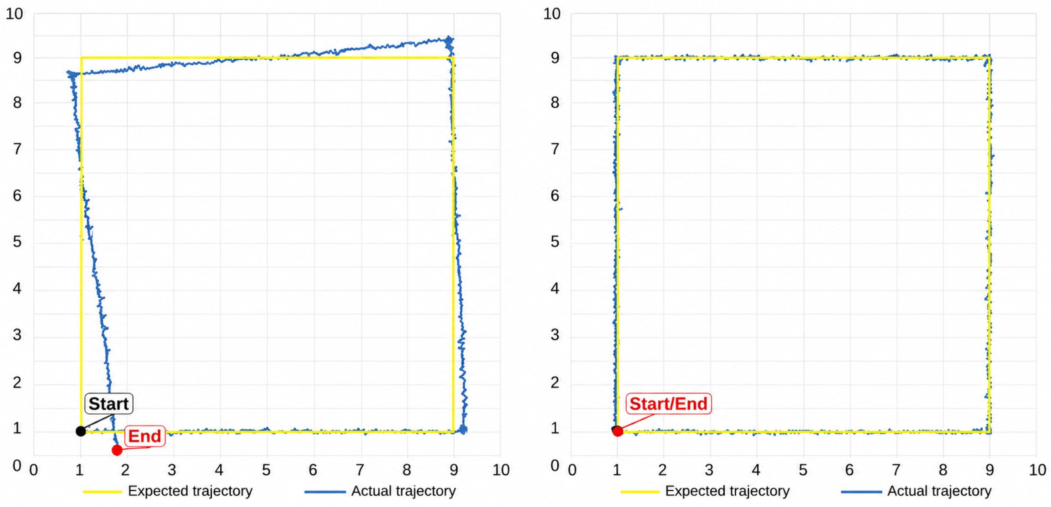
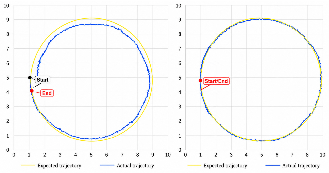
In the linear displacement tests, the reference displacement was determined from the commanded reference distance and verified using an external calibration ruler or magnetic scale placed along the test direction. For the square and circular trajectory tests, the expected trajectories were generated from preset geometric paths, whereas the actual trajectories were reconstructed from the orthogonal odometry fusion output. The start and end points are explicitly indicated in
Figure 5 and
Figure 6.
For the square trajectory test, a fixed-size aluminum-profile frame was used as the physical reference structure to constrain and verify the prescribed square path. For the circular trajectory test, an aluminum-profile support with a fixed center height and a fixed radius was used to define the reference circular path.
2.8.1. Attitude Estimation Accuracy
The gimbal was mounted on a calibration rotation platform and rotated about pitch and roll axes at angular velocities of 10 deg/s, 30 deg/s, and 60 deg/s. Reference angles were provided by the rotation platform. Dynamic tracking error and root mean square error (RMSE) were used:
Static bias was measured by holding the gimbal stationary and recording the attitude output.
2.8.2. Planar Localization Accuracy
The platform was commanded to translate along the and axes over distances of 1000 mm, 2000 mm, and 3000 mm. A calibration ruler or magnetic scale was used as the reference. Turning tests used commanded angles of 90 deg, 180 deg, and 360 deg. Composite trajectories included a square trajectory with a side length of 2000 mm and a circular trajectory with a radius of 1000 mm.
2.8.3. Passive Following Performance
The user pulled the platform through forward, lateral, and 45 deg diagonal trajectories over 5000 mm. Traction speeds were divided into low speed (200 mm/s), medium speed (400 mm/s), and high speed (600 mm/s). Evaluation metrics included the following: distance error, response time, average trajectory offset, and steady-state following error.
2.8.4. Comparative Experiments
Three comparative experiments were performed:
Pure Mecanum-wheel drive odometry versus orthogonal odometry fusion.
Uncompensated gyroscope integration, Kalman filtering only, and full compensation.
Open-loop attitude following versus closed-loop following with orthogonal odometry feedback.
2.8.5. Statistical Analysis
To improve the reliability of the experimental evaluation, each test was repeated five times unless otherwise stated. The experimental results are reported as mean values and standard deviations. The mean value was used to describe the average performance of each method or test condition, while the standard deviation was used to evaluate the repeatability and dispersion of repeated measurements.
Because the present study focuses on prototype-level engineering validation and the number of repeated trials is limited, the statistical treatment is mainly descriptive. Therefore, the comparison between different methods is based on the reported mean error, standard deviation, maximum error, relative error, and percentage improvement. Inferential statistical tests, such as confidence-interval analysis or hypothesis testing, will be further introduced in future work when larger-scale repeated experiments and complete raw measurement datasets are available.
4. Discussion
4.1. Significance of Orthogonal Passive-Wheel Odometry for Mecanum Platforms
The results show that orthogonal passive-wheel odometry is effective for improving planar localization on a Mecanum-wheel platform. Pure drive-wheel odometry is vulnerable to the same physical mechanism that gives Mecanum wheels their omnidirectional capability: roller-ground contact. During acceleration, lateral motion, diagonal motion, and start-stop cycles, drive-wheel encoder pulses do not always represent actual platform displacement. The experimental comparison in
Table 8 confirms this effect: pure Mecanum-wheel odometry produced a 24.6 mm average error over a 3000 mm trajectory, while orthogonal odometry fusion reduced the error to 3.8 mm.
The orthogonal passive wheels decouple measurement from propulsion. Their function is to roll with actual chassis displacement rather than generate driving force. Therefore, they provide a more direct measurement of planar displacement. The remaining error sources are mainly passive-wheel radius error, encoder quantization, installation non-orthogonality, ground contact quality, and heading estimation error. These errors are easier to calibrate than the Mecanum drive slip because they are less dependent on transient motor torque and roller contact state.
The non-orthogonal correction results in
Table 4 further demonstrate that mechanical installation error must be included in the model. A measured 0.28 deg angle deviation between passive-wheel axes increased position and trajectory errors, while auxiliary coordinate correction reduced the square trajectory closed-loop error from 28.4 mm to 12.3 mm. This supports the use of mechanical calibration and coordinate compensation as part of the localization module.
4.2. Naturalness and Robustness of Gimbal Posture Interaction
The gimbal posture interface provides a simple physical channel for user intention. When a user pulls the rope forward, the gimbal pitch changes; when the user pulls laterally, the roll angle changes. This creates a direct mapping between a natural pulling action and the robot’s planar motion. Unlike button control, the mapping is continuous and does not require the user to combine discrete commands for diagonal or curved motion. Unlike vision-based following, the interaction remains available under lighting changes, occlusion, and low-texture environments.
The posture-to-velocity mapping is intentionally simple. Dead-zone processing suppresses unintended motion caused by small hand tremor and sensor noise. Saturation prevents excessive speed under large gimbal deflection. Low-pass filtering and acceleration limiting reduce abrupt command changes. The experimental results show that this design achieves response times of 0.12–0.21 s depending on traction direction and speed, while maintaining trajectory offsets within tens of millimeters over 5000 mm tasks.
Compared with force-sensing handles or admittance-controlled mobile bases, the proposed interface measures posture rather than force. This choice lowers sensing complexity and avoids the need for calibrated multi-axis force sensors. However, it also means that the mapping parameters depend on rope length, gimbal stiffness, installation height, and user posture. This trade-off is acceptable for a compact companion platform, but future work should include adaptive parameter identification to improve consistency across users.
Compared with joystick control, the gimbal-rope interface preserves the physical metaphor of pulling a cart and naturally supports diagonal motion through simultaneous pitch and roll deflection. Compared with force-sensing handles, it reduces sensor complexity by using posture rather than calibrated multi-axis force. Compared with general omnidirectional platforms, the contribution of the present system is the integration of a physical traction interface with independent passive-wheel localization feedback. These advantages are practical rather than universal: joystick control may remain preferable when precise discrete commands are required, and force/admittance interfaces may be preferable when actual interaction force must be measured.
4.3. Closed-Loop Following as the Link Between Intention and Motion Accuracy
Gimbal posture alone can identify user intention, but cannot guarantee accurate platform pose. Orthogonal odometry feedback closes this gap by providing a planar localization reference. The comparison in
Table 10 shows that closed-loop feedback substantially reduces following error and trajectory offset. This indicates that the system should not treat interaction sensing and localization as separate modules. Instead, physical intention perception should generate the desired motion, and independent localization should correct the realized motion.
The same principle explains the improvement observed after gyroscope compensation. Heading error enters the coordinate transformation from vehicle-frame displacement to navigation-frame displacement. If yaw drift is not compensated, even accurate passive-wheel displacement increments can be projected into the wrong global direction. Full compensation reduced yaw drift from 12.3 deg/h to 0.45 deg/h and improved both attitude RMSE and planar trajectory accuracy.
4.4. Engineering Application Scenarios
The proposed system is suitable for application scenarios where the operator remains near the platform, and direct physical guidance is acceptable or preferred. In medical and rehabilitation settings, a rope-guided omnidirectional platform can act as a companion cart or lightweight transport base. In warehouses, laboratories, and factories, it can assist with manual material movement where a worker wants a mobile base to follow without requiring visual tracking or infrastructure. In exhibition halls, airports, and hotels, direct physical control can be safer and more predictable than fully autonomous following in dense pedestrian environments.
Example operating scenarios include a rehabilitation cart following a therapist along a bedside corridor, a laboratory trolley carrying instruments beside an operator, a warehouse picking cart moving between shelves, and a hotel or exhibition service platform moving under close human supervision. In each case, the operator remains near the platform, and the desired behavior is physically guided following rather than independent path planning.
The method may also be useful in special low-perception-dependence scenarios. For example, in a tethered air–ground cooperative setup, an aerial or external operator could provide physical guidance while the ground Mecanum platform performs precise planar movement. In such use cases, the main benefit is not full autonomy but robust motion under limited perception.
4.5. Limitations
Several limitations remain. First, the gimbal posture-to-velocity mapping parameters are currently fixed. Rope length, gimbal installation height, user height, and mechanical stiffness can change the relationship between pulling force and posture angle. Second, aggressive pulling can cause overshoot or oscillation. Although filtering and acceleration limiting reduce abrupt motion, a more systematic admittance-like dynamic model may improve comfort and stability. Third, the experiments were conducted mainly on indoor flat ground with a limited number of operators and predefined speeds. Performance under carpet, tile gaps, ramps, slopes, uneven surfaces, and long-term operation requires further validation. Finally, the present system provides relative localization; long-distance operation may still require external references or loop correction.
In addition, the current prototype does not include AI-based task planning or semantic scene understanding. Such functions could be added as an upper-level planning layer in future work, but they are outside the scope of this study, which focuses on the lower-level interaction, localization, and motion-control chain. The compact rectangular chassis is also a prototype choice; practical deployment in complex internal workspaces would require enclosure design, edge protection, payload-specific stability analysis, and additional obstacle-safety measures.