1. Introduction
Transfemoral amputation results in the loss of knee joint function, imposing severe physical constraints on patient mobility and quality of life [
1]. In developed countries, dysvascular disease associated with population aging and diabetic foot complications has recently emerged as a primary cause of amputation [
2,
3]. In developing countries with limited medical infrastructure and in conflict-affected regions, however, trauma-related amputations among young and middle-aged individuals are reported at markedly higher rates [
4,
5]. To resume economic activity, these individuals require mobility at or above the K3 functional level with variable-speed gait capability. Achieving K3-level performance at a delivered unit cost below approximately 1500 USD within constrained public-assistance budgets remains a major technical challenge in low-cost prosthesis development [
6,
7]. Given the cost-effectiveness limitations of existing high-end devices [
8,
9,
10], there is a persistent need for durable, widely accessible rehabilitation solutions capable of withstanding demanding use environments.
Over the past decade, research on knee prostheses has progressed beyond demonstrating the biomechanical benefits of microprocessor-controlled knee systems (MPKs) [
11]; current trends are shifting toward active assistive control in powered lower-limb wearable robotics, spanning both exoskeletons and powered prostheses [
12,
13]. These systems integrate networks of high-precision IMUs and angular sensors [
14] with machine-learning-based continuous gait pattern recognition algorithms for variable damping control [
15]. They can therefore enhance gait stability during stumble recovery and on uneven terrain; fear of falling and related activity avoidance are recognized outcomes in this population [
16]. Such advances, however, are accompanied by increased system weight and higher power requirements arising from complex sensor fusion. Conventional hydraulic MPK systems in particular require continuous power for valve actuation to regulate high-viscosity fluids, and may revert to a fixed safety mode upon battery depletion, potentially disrupting gait continuity [
17]. The high acquisition cost of these advanced devices likewise often exceeds the scope of public-assistance programs in developing regions [
18], limiting access for the majority of amputees worldwide [
19].
To reduce these computational, power, and cost demands, simplified single-sensor schemes have been used for gait-event detection; a single waist-worn IMU, for instance, has proved sufficient [
20]. This body-mounted modality differs from the joint-integrated sensing adopted here, in which a single Hall-effect sensor tracks knee flexion–extension to determine gait phase. A closely related low-cost approach, also based on a passive four-bar polycentric knee with a single Hall-effect sensor, has been reported [
8]. In that work the sensor was used primarily to trigger stumble-locking, the variable damper was not operated in variable mode, and gait-speed-adaptive variable damping was noted as future work. Building on this direction, the present study uses the single-sensor signal to modulate speed-adaptive semi-active pneumatic swing damping, differing in the actuation medium and in relying on the four-bar geometry itself for passive stance stability.
Under these budgetary and infrastructural constraints, commercially available mechanical prostheses equipped with pneumatic cylinders, such as the OP5, represent one practical option for K2 to K3 patients in resource-limited settings [
21,
22]. Pneumatic systems offer advantages over hydraulic systems in lower weight and greater compliance. The inherent compressibility of air, however, makes precise link rotation speed control difficult [
23] and introduces a risk of knee buckling under load-bearing conditions, particularly when stance-phase pressure fails to reach the threshold required for damping engagement [
24]; this limitation contributes to their reduced utilization in the modern MPK market [
25]. In addition, such systems typically operate only upon reaching predefined pressure thresholds or exhibit structurally fixed damping at specific walking speeds. Patients who walk slowly or exhibit insufficient weight acceptance during the stance phase may fail to generate adequate pressure to activate variable damping. During high-speed walking, conversely, fixed orifice (FO) structures may be unable to accommodate the elevated compressed-air flow demand, resulting in extension lag.
This mismatch in load and speed adaptability induces asymmetric compensatory movement characterized by excessive recruitment of the hip flexors [
26,
27]. Such compensations increase the demand for intensive gait training while contributing to mechanical overload of the intact limb [
27] and elevated overall metabolic cost [
28]. These biomechanical imbalances are recognized as major risk factors for prosthesis abandonment [
29] and secondary osteoarthritis in the intact limb [
30].
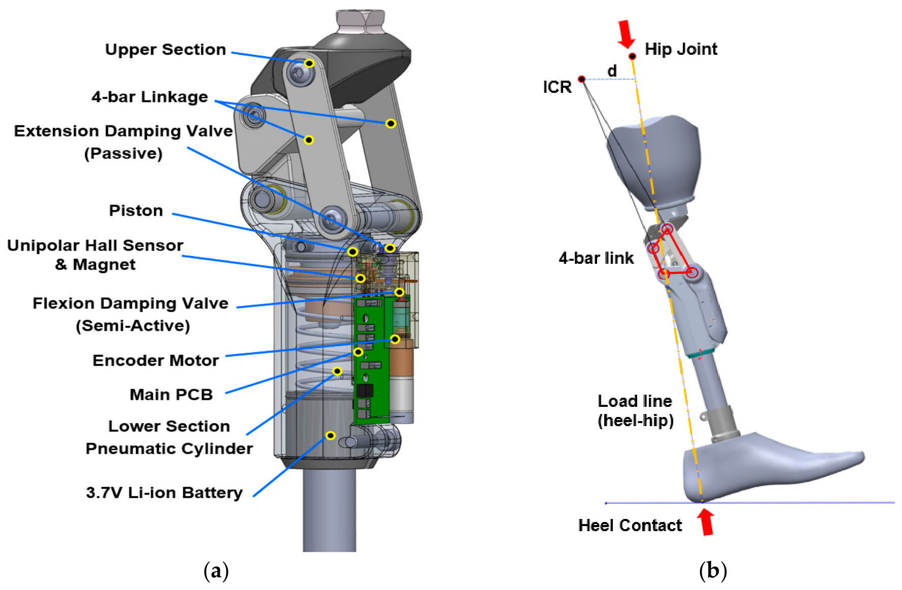
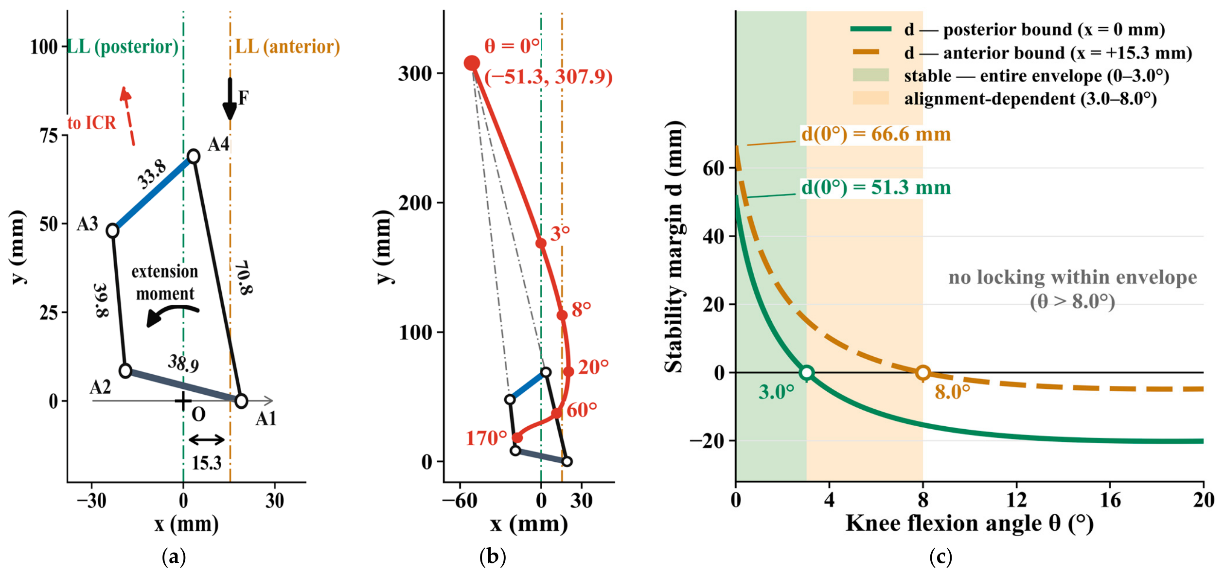
In this study, the kinematic characteristics of pneumatic systems are revisited, and the feasibility of an electronically controlled pneumatic knee (ECPK) architecture is explored as a candidate cost-effective design. The core approach of this work is functional decoupling. To mitigate stance-phase instability, a primary limitation of pneumatic systems, a four-bar linkage is employed to position the instantaneous center of rotation (ICR) posterior to the load line, inducing passive structural locking without power consumption [
31,
32,
33]. Prior kinematic analyses of such elevated-ICR configurations report stability margins consistent with resistance to buckling under typical stance loading [
33], providing a basis for the passive locking strategy adopted here; the corresponding margins for the present linkage are quantified in
Section 2.1.1. Because high-load stance support is provided by the linkage geometry, no actuator energy is used during stance, and, over the near-extended stance range analyzed in
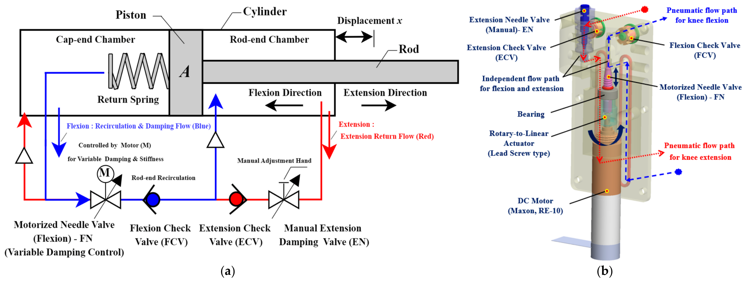
Section 2.1.1, stance security does not depend on the controller functioning correctly. The controller and the Hall sensor nevertheless run continuously throughout the gait cycle, since stance duration is itself the measured quantity; what is confined to the swing-phase transition is valve actuation, not electrical operation. The system integrates anticipatory valve flow-path control according to gait phase with air-compression regulation, enabling semi-active control of the linkage’s rotational velocity and damping characteristics.
Speed-adaptive electronic modulation of pneumatic swing damping at the knee is not new. The first commercially available microprocessor-controlled knee inferred walking speed from onboard sensing and adjusted a pneumatic swing-control valve accordingly, while leaving stance support to a mechanical, weight-activated mechanism [
34,
35]. Related pneumatic–hydraulic strategies have been demonstrated at the ankle [
36], and semi-powered designs have combined microprocessor valve control with a small assist motor at the knee [
24]. The present work is therefore positioned within this lineage rather than apart from it. What distinguishes the configuration described here is a combination of design choices, set out column-wise in
Table 1, that the structured literature search did not identify together: stance support obtained from the four-bar geometry rather than from the actuator, so that no actuator energy is spent in stance and, over the analyzed near-extended range, stance security does not depend on the controller functioning correctly; gait-phase and speed estimation reduced to a single joint-axis sensing channel; and valve actuation confined to discrete mode transitions, with the valve holding its position without current in between.
The inherent compliance of air is further used as a shock-absorbing mechanism to stabilize gait under external perturbations, and a strategy for reducing metabolic cost through regulation of compensatory movement is also examined [
37]. From a control perspective, complex sensor fusion is avoided, as gait-phase and speed estimation rely on a single joint-axis Hall sensor. A motor-integrated encoder and a current-sensing circuit are also present, but they serve only needle-valve position feedback and power-up home calibration, respectively, and do not contribute to gait sensing.
A discrete-state anticipatory feedforward controller estimates the speed of the next step from a two-step moving average of the stance time, taken over the current and immediately preceding gait cycles [
38]. While recent active prostheses increasingly adopt machine learning or Kalman filters for gait prediction, historical moving averages remain a robust, rule-based approach validated for real-time prosthesis control [
39]. In robotics more broadly, safe real-time motion is often achieved through hierarchical quadratic programming and priority-based multi-objective control [
40]. Such formulations offer strong guarantees but assume computational and sensing resources unavailable in a low-cost prosthesis; the present design instead pursues the opposite end of this trade-off with a rule-based, single-channel, anticipatory feedforward controller.
Relying on a single gait-sensing channel, this lightweight control architecture reduces processing latency, sensor-fusion complexity, and power consumption, which are key requirements for resource-constrained environments [
38]. The approach presets the needle valve prior to swing-phase entry, thereby bypassing the pressure dependency of conventional pneumatic systems and compensating for the mechanical response delay of pneumatic valves in an anticipatory manner. Although this estimation based on prior-step data may introduce phase lag under rapid acceleration or deceleration, it provides a viable alternative for K2 to K3 users performing level walking and gradual speed transitions, enabling variable-speed extension with minimal computational resources. Even under computational delay or power loss, the closed kinematic chain of the four-bar linkage preserves its geometry independently of controller state [
31,
33]; within the near-extended corridor analyzed in
Section 2.1.1, stance support is therefore not contingent on the electronics. The analysis supporting this is quasi-static and does not cover initial contact. Structural strength was verified to KS P ISO 10328:2016 [
41] (see
Section 2.1.1).
This study is a single-case feasibility study investigating whether the proposed ECPK system improves gait symmetry and reduces net metabolic energy cost relative to a conventional passive mechanical knee, despite the added distal mass of its electronic components. Following the well-established precedent for single-subject case designs in early prosthetic device validation [
42], a within-subject comparative experiment was conducted with a highly experienced transfemoral amputee with 15 years of prosthesis use (N = 1), using a passive commercial mechanical prosthesis (OP5) as the comparator condition. The study was conducted according to the guidelines of the Declaration of Helsinki and approved by the Institutional Review Board of the Rehabilitation Engineering Research Institute (Approval No. RERI-IRB-221130: 30 November 2022), and its findings are interpreted as hypothesis-generating rather than generalizable. Following a 4-week adaptation period with the ECPK system, evaluations were performed using the six-minute walk test (6MWT) [
43], center-of-pressure trajectory analysis to characterize load-bearing symmetry control and gait symmetry [
44,
45], and respiratory gas-based metabolic measurement [
46] to assess trends in dynamic stability and metabolic efficiency under the weight-penalty condition.
To position the proposed design among existing devices, representative passive, microprocessor-controlled, semi-powered, and powered knees were identified through a structured search of Scopus, PubMed, IEEE Xplore, and Google Scholar (the term “transfemoral prosthetic knee” combined with pneumatic, hydraulic, magnetorheological, semi-active, microprocessor, and polycentric; English-language records, 2000–2026), supplemented by backward citation chaining for earlier seminal work and by manufacturer documentation for commercial devices not described in the peer-reviewed literature; this served to position the present design rather than as a systematic review.
As summarized in
Table 1, fully powered and microprocessor-controlled knees offer full speed adaptability and active stance control, but they depend on continuous power, multiple sensors, and considerably higher mass and cost. Fully passive low-cost knees avoid these burdens, although their swing resistance cannot be adjusted electronically. It should also be acknowledged that speed adaptation is not unique to the present design; some commercial passive knees approximate it through flow-dependent mechanical valving [
47], and comparable or lower mass and cost have been reported for several recent low-cost prototypes [
48,
49].
The main contributions of this study are as follows. First, a structure that combines the passive kinematic locking of a four-bar linkage with the compressibility of air is evaluated as a candidate low-cost complement to hydraulic MPK systems. Second, the extent to which single-gait-sensor-based anticipatory control can offset the physical penalty of an additional distal mass of approximately 400 g through kinematic assistance is examined in a single-case study, with net metabolic energy cost as an outcome measure. Third, the effect of anticipatory flow regulation on extension lag and gait symmetry relative to a conventional passive device is preliminarily characterized.
Table 1.
Literature-based positioning of the proposed ECPK against representative passive, microprocessor-controlled, semi-powered, and powered transfemoral prosthetic knees.
Table 1.
Literature-based positioning of the proposed ECPK against representative passive, microprocessor-controlled, semi-powered, and powered transfemoral prosthetic knees.
| Category (Representative Device) | Stance-Phase Support | Power in Stance | Swing-Speed Adaptation | Gait-Sensing Channels | Ref. |
|---|
| Passive pneumatic polycentric, manually set (Össur OP5; comparator in this study) | Polycentric geometric | None | Passive rate-dependent only; orifice fixed at fitting and not adjusted automatically or electronically (rated ≈ 5 km/h) | None | [22,50] |
Passive pneumatic polycentric, mechanically auto-adaptive
(Össur Paso Knee) | Polycentric geometric | None | Automatic, continuous, purely mechanical (≤7 km/h); not programmable or subject-calibrated | None | [47] |
| Low-cost MPK on a passive four-bar frame (E-Knee; Galey & Gonzalez) | Four-bar geometric + MP-triggered clamp | On demand | Damper not operated in variable mode; speed adaptation stated as future work | Single joint-axis
Hall sensor | [8] |
| Low-cost magnetorheological MPK (i-Inspire; Qadir et al.) | Active MR | Continuous | Full | Multi-sensor
(angle, force, tilt) | [49] |
| Microprocessor pneumatic swing, uniaxial (Blatchford IP/SmartIP) | Uniaxial, Mechanical,
weight-activated | None (powered in swing only) | Automatic, continuous | Onboard sensing only (no external gait sensors) | [34,35] |
| Commercial MPK, hydraulic or MR (Ottobock C-Leg 4; Össur Rheo Knee) | Active microprocessor stance | Continuous | Full | Multi-sensor | [51,52] |
| Semi-powered stance-control swing-assist (Vanderbilt SCSA; Lee et al.) | Active hydraulic
(valve closed in stance) | ≈6 W | Closed-loop, cadence-adaptive | IMU, encoders, load cell | [24] |
Powered/motorized
(Össur Power Knee) | Powered stance support | High
(active drive) | Full, incl. stairs and ramps | Multi-sensor | [53] |
Proposed ECPK (this work);
pneumatic semi-active | Four-bar geometric
(passive); independent of the controller | None; no holding current | Discrete three-mode, swing only; subject-calibrated LUT indexed by measured stance time | Single joint-axis
Hall sensor | This study |
3. System Architecture and Control Strategy
3.1. Hardware Architecture and Embedded System
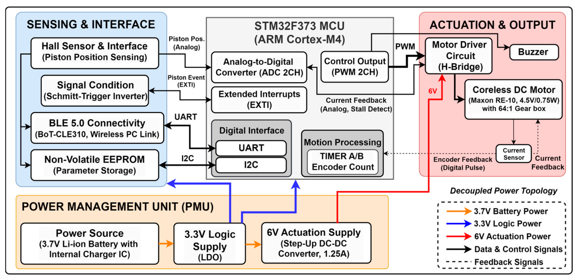
This section presents the architecture of a custom-designed embedded control unit (ECU) that performs gait phase detection and real-time position control of the flexion needle valve (FN). The system comprises a microcontroller (MCU, STM32F373, STMicroelectronics, Geneva, Switzerland) a power management unit (PMU), an actuation subsystem, a sensing subsystem, and a communication interface, as shown in the overall block diagram (
Figure 4).
The sampling and computation cycle, which forms the core of the control system, was designed based on the biomechanical limitations of the target patient population. Assuming a maximum walking speed of 4.5 km/h (approximately 1.25 m/s), corresponding to a step frequency of approximately 2 Hz for transfemoral amputees during daily activities, a control cycle of 100 Hz (10 ms) is applied to manage timing delays during gait phase transitions. However, due to the mechanical time constant of the actuator responsible for valve operation, some delay in damping response is unavoidable. To compensate, the system analyzes the preceding step and incorporates a feedforward control strategy that presets the valve accordingly.
The firmware is implemented using FreeRTOS to ensure stable execution of priority-based multitasking. The sensor data acquisition and gait phase detection loop is assigned the highest priority and operates at 100 Hz, while the Bluetooth transmission task is executed asynchronously at 20 Hz (50 ms) and gait data are recorded to the host at 10 Hz (100 ms) to prevent unnecessary power consumption and control bottlenecks. Direct memory access (DMA) and the nested vectored interrupt controller (NVIC) are used so that peripheral communication does not delay the main control loop.
The PMU is designed around a 3.7 V, 3350 mAh lithium-ion battery (T11-S3350S, LUNAVOLT, Seoul, Republic of Korea) to ensure system portability. To enhance system stability, a decoupled power architecture is adopted in which logic power and actuation power are physically separated. A regulated 3.3 V supply via a low-dropout (LDO) regulator is provided to the noise-sensitive MCU and sensing subsystem, while an independent 6 V supply is delivered to the motor subsystem through a step-up DC–DC converter to support high inductive loads. This topology prevents brownout of the 3.3 V logic circuit under voltage-drop conditions caused by high current draw during valve motor startup and mitigates the influence of battery-level fluctuations on valve control torque.
The actuation subsystem is the core module responsible for regulating flexion damping. It comprises an ironless-core DC motor (RE 10, 0.75 W, 4.5 V nominal, 222 mA maximum continuous current; maxon motor ag, Sachseln, Switzerland) coupled to a 64:1 planetary gearhead (GP 10 A). An H-bridge driver supplied from the boosted 6 V rail actuates the motor to adjust the orifice cross-sectional area of the needle valve, with pulse-width modulation giving an effective terminal voltage of 5.42 V. At this operating point the motor turns at approximately 11,600 rpm, within the gearhead’s maximum continuous input speed of 12,000 rpm, yielding an output-shaft speed of approximately 181 rpm, and draws approximately 63 mA, 28% of its maximum continuous rating. The needle valve has a total travel of 8 turns, of which the settings calibrated for the participant in this study span 1.8 turns; a transition across that span therefore completes in about 0.6 s.
The commanded valve position is retained without holding current: the fine-pitch thread of the needle valve is self-locking against the axial seat reaction, so the setting is held by the valve itself rather than by the drivetrain. Motor current therefore flows only during a mode transition, and the last commanded damping setting persists if power is interrupted. Rather than employing several high-cost actuators, the hardware budget is concentrated on the valve actuation unit, which is the only semi-active element, so that actuation reliability is obtained at low cost.
The sensing subsystem includes a Hall sensor (DRV5056, Texas Instruments, Dallas, TX, USA) for gait-phase detection, a motor-integrated encoder for needle-valve position feedback, and a current-sensing circuit for monitoring motor load. Gait phase and speed are estimated from the Hall sensor alone. The encoder closes the needle-valve position loop and the current-sensing circuit performs power-up home calibration; neither enters the gait-sensing path. The current-sensing circuit detects the stall current generated when the valve reaches its mechanical end-stop during power initialization, enabling automatic calibration of the absolute home position. The “single-sensor” description in this work therefore refers specifically to the single-channel gait-estimation pipeline, not to the total sensor count of the device.
The MCU references a pre-tuned lookup table (LUT) to set the target encoder pulses corresponding to the desired valve opening and performs threshold-based position control by terminating motor drive once the pulse target is reached. Inertial overshoot resulting from high-speed rotation is mechanically suppressed by the resistance of the 64:1 reduction gear, allowing the system to achieve the required damping resolution within the required timeframe without complex feedback computation.
The connectivity and interface subsystem incorporates a low-power Bluetooth module to support wireless communication with a host PC. The dedicated GUI software developed for this system is used to log gait data in real time during clinical experiments and to tune control parameters. User-specific parameters are stored in onboard nonvolatile memory (EEPROM) via I2C communication, ensuring that personalized settings are retained after power cycling.
3.2. Control Algorithm and Safety Interlocks
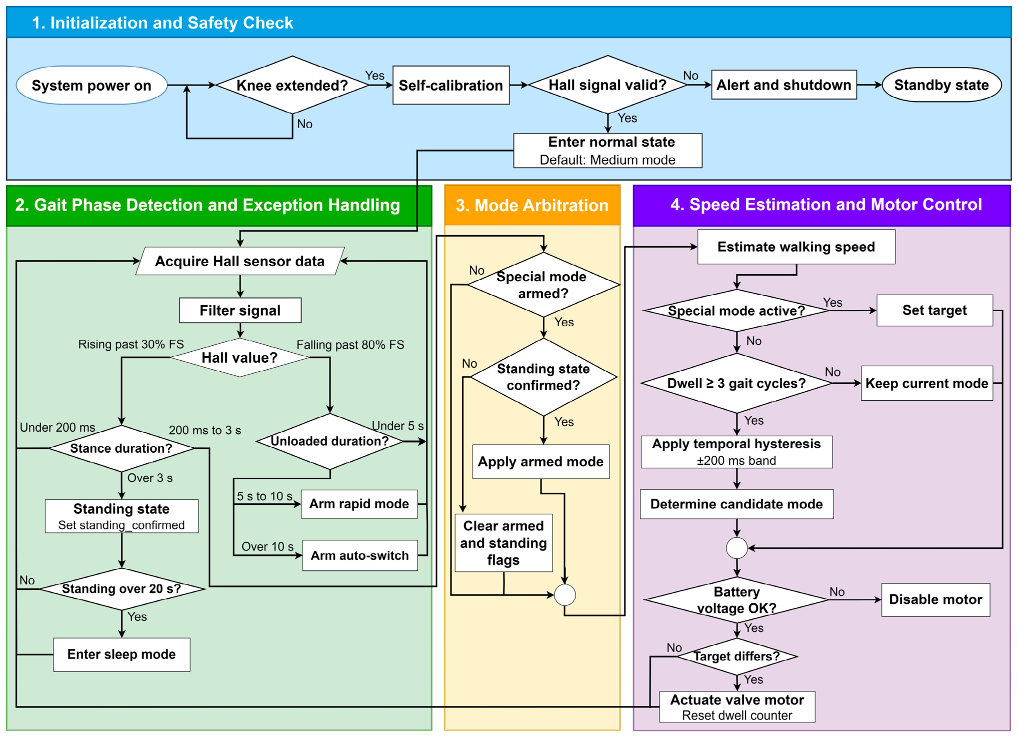
The control logic is implemented as a deterministic four-layer architecture, each layer corresponding to one block of the flow shown in
Figure 5.
The first layer performs initialization and homing. At power-up the controller confirms that the knee is extended, drives the FN motor across its full travel to a mechanical end-stop so that the encoder count can be referenced to an absolute position, and checks the Hall-sensor ADC value to verify sensor connectivity. If either check fails, motor actuation is disabled and the system remains in a standby state after a buzzer alert. On successful initialization the controller enters the normal state with the valve at the Medium setting.
The second layer segments the gait cycle and handles exceptions. The Hall signal is sampled at 100 Hz and compared against a rising threshold of 30% and a falling threshold of 80% of the sensor full scale, which divides the signal into near-extended and flexed intervals; these are used as proxies for the stance and swing phases, since the sensor resolves knee angle and not limb loading. Loaded intervals shorter than 200 ms are discarded as contact bounce at terminal impact. A loaded interval longer than 3 s sets the standing flag and holds the valve at its current position, and a standing state sustained beyond 20 s places the controller in a low-power state, from which a Hall-sensor interrupt restores normal operation. Unloaded intervals longer than 5 s are interpreted not as swing but as user input: 5–10 s arms the rapid mode, which fixes the valve at maximum damping, and more than 10 s arms the auto-switch toggle, which enables or disables stance-time-based automatic mode switching. Prolonged sitting therefore does not enter the low-power state; it is resolved in the third layer.
The third layer arbitrates these user-activated modes. The gesture is a standing knee flexion, which the controller observes as the prolonged unloaded interval defined above, so that no smartphone or button input is required. Because a single sensor cannot separate this gesture from ordinary sitting, an armed gesture is not applied when it is detected: it takes effect only after the standing flag of the second layer has been set, that is, after a loaded interval of at least 3 s. The arbitration block then applies the armed mode and clears both the armed and standing flags. A sit-to-stand transition followed by immediate walking does not produce a 3 s loaded interval, so a gesture armed during sitting is cleared without changing the mode. This pairs a postural gesture with a physical confirmation criterion and avoids additional sensor fusion, although unintended activation remains possible when the user stands still for an extended period after flexing the knee; a secondary interlock, for example a gyroscope, is left to future work.
The fourth layer estimates walking speed and commands the valve. When a special mode is active, the lookup table is bypassed and the corresponding target is applied. Otherwise, two gates are evaluated in sequence. The first is a dwell condition: after each actuation no further transition is admitted for three gait cycles, and while this lockout is in effect, the boundary is not evaluated and the current mode is retained. The transition itself is not delayed—a boundary crossing is committed immediately once the lockout is clear; the lockout stabilizes the newly selected mode by preventing an immediate reversal. The second is a temporal hysteresis of ±200 ms applied to the lookup-table boundaries, so that each boundary is separated into distinct upward and downward switching values; at the Medium–Fast boundary of 700 ms, an upward transition requires a mean stance time below 500 ms and a downward transition a value above 900 ms. The two gates act after a transition to stabilize the newly entered mode—the hysteresis widening the stance-time margin a reversal must clear, and the lockout blocking any transition for three cycles—and were combined because the mode oscillation reported in
Section 4.3 was confined to the boundary regions. The candidate mode obtained in this way is mapped to a valve target through the lookup table (Equations (3) and (4)); the motor is driven only if the target differs from the current position and the battery voltage is adequate; the lockout counter is set on each actuation and counts down over the following three cycles.
The ±200 ms band and three-cycle dwell were fixed by offline replay of
Section 4.3 log rather than tuned freely. Over the 3.2–3.7 km/h band the two-step mean stance time had a mean of 677 ms and a standard deviation of 109 ms, so a ±200 ms band spans approximately ±1.8 SD of the recorded scatter; the three-cycle dwell matches the two-to-three-step interval over which a genuine speed change persists in the moving-average estimate. These were the smallest values that removed the boundary reversals in that log.
These two gates were introduced in the present revision and were not active during the treadmill and overground experiments reported in
Section 4.3 and
Section 4.4. Their parameter values were obtained by offline replay of the gait data logged in
Section 4.3, and the implemented firmware was subsequently verified against that same recorded input; the resulting change in the number of mode transitions is reported in
Section 4.3 and discussed in
Section 5.2.
3.3. Signal Processing and Gait Phase Classification
To ensure stable estimation of stance time (
), the primary indicator for gait speed estimation, the proposed system employs dynamic normalization and a multistage filtering approach.
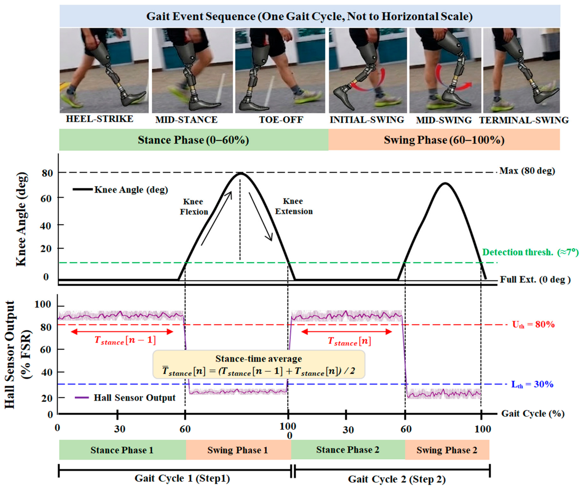
Figure 6 illustrates the output characteristics of the Hall sensor in relation to changes in knee joint angle during gait. The sensor produces a maximum output voltage when the knee reaches full extension and the magnet is in close proximity, while the voltage decreases as magnet-to-sensor distance increases during flexion.
Rather than relying on fixed absolute voltage thresholds that may vary due to environmental factors, gait phase detection is normalized based on the full-scale range (FSR) of the sensor output. The system is mechanically designed such that the voltage variation across the full range of knee motion spans at least 60% of the sensor operating range. This ensures a sufficiently high signal-to-noise ratio (SNR) relative to electromagnetic noise generated by the actuation subsystem and provides a clear phase transition margin.
For gait phase detection, dual thresholds are applied at the lower 30% () and upper 80% () levels. To improve the accuracy of speed estimation, the system initiates stance-phase detection as soon as the knee begins to extend and the sensor signal rises above the lower threshold (, 30%), whereupon the stance timer is started. Conversely, when the knee begins to flex and the sensor signal falls below the upper threshold (, 80%), the system transitions to swing phase, and the accumulated time at that moment is defined as the final stance time ().
This threshold separation is intended to suppress spurious phase transitions caused by small fluctuations in the sensor signal. It acts on the raw Hall signal and is distinct from the temporal hysteresis applied to the lookup-table boundaries in
Section 3.2. The raw sensor data are first digitized through the MCU ADC and then processed through a low-pass filter (LPF) to attenuate high-frequency noise, followed by a moving average filter to smooth residual noise. Because this multistage digital filtering inherently introduces phase delay, the algorithm requires a trade-off in filter window size selection to preserve real-time responsiveness in gait phase detection. The final gait mode decision is made at the moment of swing phase entry. To reduce stochastic variability within a single gait cycle, the system computes and applies the average of the stance time from the current cycle (n) and the preceding cycle (n − 1), as expressed in Equation (4), in real time.
This smoothing partly offsets the stride-to-stride variability caused by uneven terrain or brief changes in step length. By avoiding abrupt damping changes, the controller is less likely to overreact to momentary speed fluctuations and instead follows the user’s dominant gait intent.
3.4. ECPK GUI Software for Gait Analysis and Parameter Tuning
A custom GUI software was developed to enable real-time data logging of the ECPK system and subject-specific adjustment of control parameters.
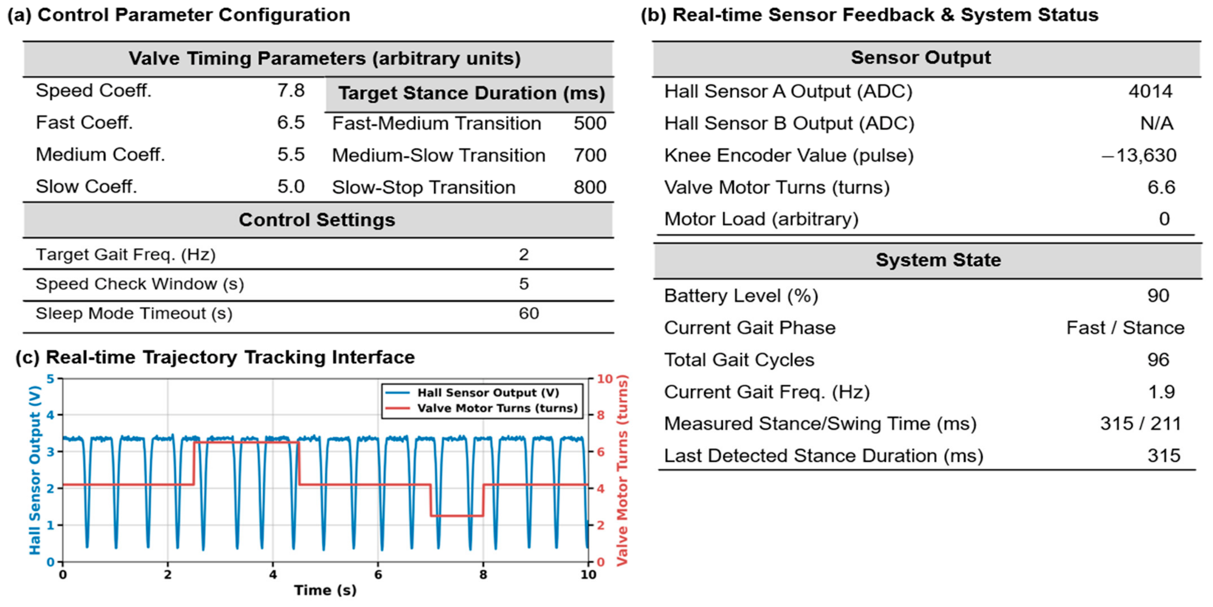
Figure 7 presents a schematic diagram illustrating the functional configuration and data flow of the developed software and shows the logical structure of a human–machine interface (HMI) that allows researchers to monitor internal system states and adjust control variables to the experimental conditions during clinical testing. The software architecture consists of two main components: control parameter configuration and real-time monitoring.
The control parameter configuration module shown in
Figure 7a defines system responsiveness based on the subject’s gait characteristics. In this module, the researcher sets the stance duration thresholds that determine gait mode transitions, together with the target control value for each mode (Slow, Medium, Fast). The system classifies the gait as Fast Mode when the real-time computed average stance time (
) falls below the Fast–Medium threshold. The target control values are directly linked to the motor target position and determine the extent to which the orifice is closed, thereby increasing damping force. The settings displayed in
Figure 7a are firmware defaults shown to illustrate the interface; the thresholds and valve positions applied in the present experiments are those established by the per-user calibration procedure described in
Section 4.2.2.
Figure 7b,c present the monitoring and visualization interfaces that process system state feedback. The state monitoring block in
Figure 7b displays key variables in real time, including raw ADC data from the Hall sensor, current gait phase, and battery level. The real-time trajectory tracking interface in
Figure 7c enables observation of the dynamic tracking behavior between sensor input and actuator output. The plot is a representative snapshot from a bench-top test: the valve motor steps to each target position as the sensor signal cycles. System latency and mode transitions can therefore be observed directly during testing, which supports the parameter tuning described in
Section 4.2.2.
3.5. System Implementation and Prototype
The hardware architecture and control algorithm proposed in this study were integrated into a physical prototype to enable mechanical validation and gait evaluation.
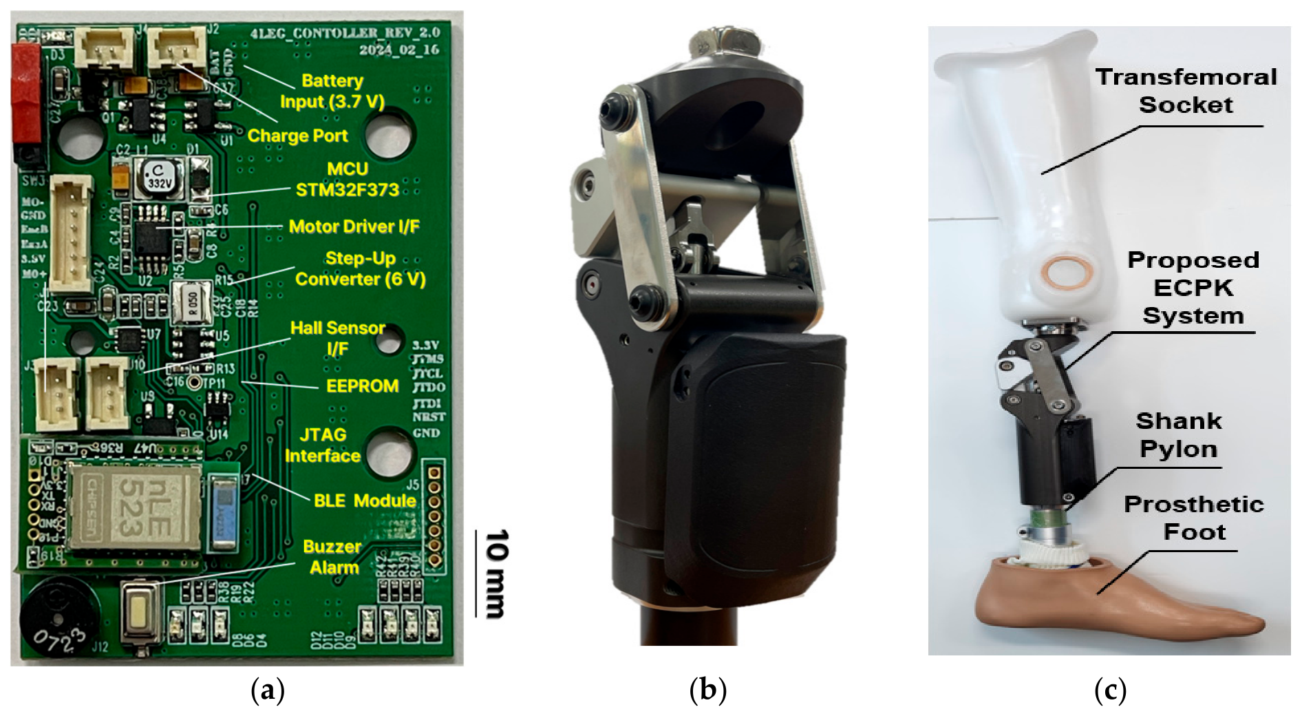
Figure 8 presents the implemented ECPK system reflecting the design specifications described in
Section 3.
Figure 8a shows a custom-designed ECU developed to minimize computational bottlenecks and power interference. It integrates the main controller (STM32F373, STMicroelectronics) responsible for computation, a wireless module (BLE) for GUI communication, and a 6 V step-up converter for power decoupling of the actuation subsystem.
Figure 8b presents a custom-fabricated variable damping knee module that integrates a coreless motor with the flexion needle valve. To control extraneous variables during subsequent clinical experiments, these core modules were mechanically integrated, as shown in
Figure 8c, with the subject’s existing transfemoral socket and prosthetic foot to form a complete transfemoral prosthesis. The integrated system served as the evaluation platform for mechanical impedance bench testing and clinical gait assessment described in
Section 4.
4. Experimental Results
The ECPK is evaluated first on the bench and then during gait. First, the dynamic characteristics of the variable damping mechanism are quantitatively assessed using a precision universal testing machine, followed by an exploration of potential improvements in gait symmetry and metabolic efficiency compared with a conventional commercial prosthesis through a within-subject comparative evaluation involving a participant with transfemoral amputation (N = 1).
4.1. Analysis of Mechanical Impedance and Damping Characteristics
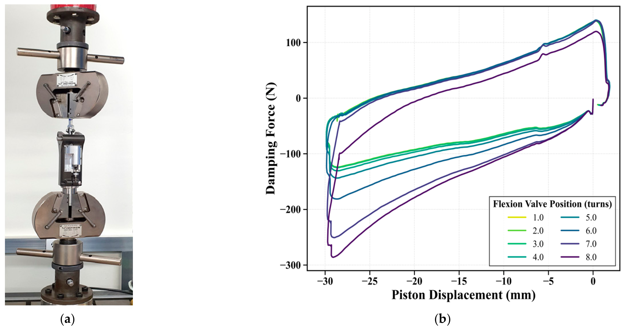
The ECPK dissipates the kinetic energy of the swinging shank by throttling airflow between the cylinder chambers, so its damping is set jointly by the needle-valve orifice area and by the piston velocity. To separate these two effects, the pneumatic cylinder was tested on materials testing machines under two conditions: valve position varied at a fixed piston velocity, and piston velocity varied at a fixed valve position.
In the first test (Instron R8511;
Figure 9a), the piston was driven at 130 mm/s over a 30 mm compression stroke while the flexion valve was closed from 1.0 (fully open) to 8.0 turns (maximum restriction) in unit steps, with the extension valve fully open. Negative displacement corresponds to flexion (compression) and positive to extension. The force–displacement curves (
Figure 9b) follow the expected trend: as the flexion valve closes, the compressive resistance rises, reaching about −280 N at −30 mm for 8.0 turns—roughly 2.3 times the value near the open setting (2.0 turns, ≈−120 N)—and above 6.0 turns the force stiffens nonlinearly with displacement, consistent with air compression in a confined volume. Each valve setting was recorded once;
Figure 9b therefore indicates the range of damping the controller can command at this velocity but does not, on its own, establish repeatability or the velocity dependence of the damping.
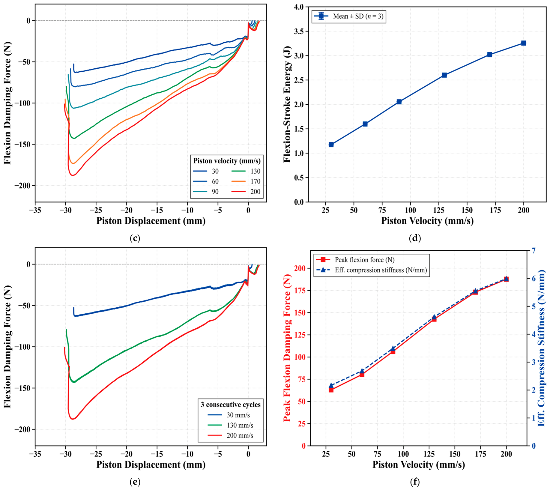
Because a fluidic damper is inherently rate-dependent, a second test characterized this velocity dependence directly (Instron ElectroPuls, Instron, Norwood, MA, USA). With the flexion valve held at 5.0 turns, the piston velocity was set to 30, 60, 90, 130, 170, and 200 mm/s, and three cycles were recorded at each speed. The analysis is confined to the flexion (compression) stroke, which produces the swing-phase damping of interest; the extension stroke, whose force depends on the extension-valve setting, was not examined here. The results are given in
Table 4 and
Figure 9c–f.
The flexion force–displacement curve grew with velocity (
Figure 9c). Over the compression stroke, the absorbed energy increased from 1.18 ± 0.01 J at 30 mm/s to 3.26 ± 0.01 J at 200 mm/s (
Figure 9d), the peak flexion force from 63 to 188 N, and the secant compression stiffness from 2.2 to 6.0 N/mm (
Figure 9f). Because this stiffness rises with velocity, it reflects the combined pneumatic-spring and flow-restriction response rather than a rate-independent modulus and is reported as an indicative value. The three cycles at each velocity nearly coincided (coefficient of variation < 1%;
Figure 9e). At 130 mm/s the 5.0-turn condition gave a peak flexion force of ≈143 N, agreeing with the 5.0-turn curve of
Figure 9b measured at the same velocity.
The two tests describe complementary parts of the same behavior: valve position sets the level of damping available to the controller, while at a fixed valve position the damping scales with piston velocity through the intrinsic response of the cylinder. The lookup table uses this by assigning a valve position to each detected speed, so that faster swing meets greater fluidic resistance. These measurements were confined to the bench; the extension-stroke rebound, the in-cylinder pressures, and any temperature dependence were not measured, and the associated kinematic effects are assessed in the gait evaluation that follows.
4.2. Single-Case Gait Experiments and Protocol
4.2.1. Participant and Experimental Setup
This section presents the single-case feasibility evaluation designed to quantitatively assess the real-time gait assistance performance of the proposed ECPK system. A single-subject, within-subject design (N = 1) was used with an experienced individual with unilateral transfemoral amputation, chosen to minimize confounding variables while establishing initial feasibility and recording baseline kinematic responses to the new control system. The study was conducted in compliance with ethical guidelines, with approval from the Institutional Review Board (IRB) of the Rehabilitation Engineering Research Institute (approval no. RERI-IRB-221130), and written informed consent was obtained from the participant following a full explanation of the study purpose and procedures.
The participant was a female with right-sided transfemoral amputation who had a relatively long residual limb, providing a favorable moment arm for prosthetic control. To minimize between-condition variability, an experienced prosthesis user who had used a passive polycentric mechanical prosthesis (Össur OP5) for more than 15 years was selected. Because the participant’s motor memory and gait pattern were strongly adapted to the comparator, the OP5 serves as a stringent baseline against which any change introduced by the new system must be read. The same 15-year-versus-4-week adaptation asymmetry is, however, a confound that limits interpretation and is treated as such in
Section 5.3. Taken together, these characteristics make this a single-case engineering feasibility study intended to establish integration and control viability rather than a clinical-effectiveness trial; the favorable moment arm and single-participant design limit generalizability, and all outcomes are interpreted as hypothesis-generating.
Pre-experimental gait analysis confirmed that the participant was capable of a wide range of walking speeds when using the conventional passive mechanical prosthesis (OP5), from a minimum of 2.3 km/h (75.1 steps/min) to a peak walking speed of 4.3 km/h (120.2 steps/min) over short distances. This indicates that the participant could sustain a broad range of walking speeds, which defined the range over which the ECPK’s variable damping was subsequently evaluated.
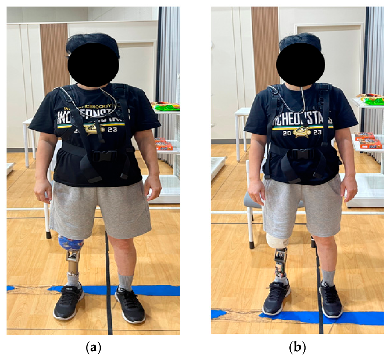
The experiment was conducted using a within-subject comparative design comparing the control condition (wearing OP5) and the experimental condition (wearing ECPK). To control baseline conditions, the transfemoral socket, pylon, and prosthetic foot were kept identical to those used by the participant, and only the knee module was replaced to isolate the effects of changes in knee kinematics and control strategy on gait, as summarized in
Table 5. The experiment was performed on a treadmill (h/p/cosmos Mercury, Nussdorf-Traunstein, Germany) with precise speed control and clinical-grade certification. Ground reaction force and COP data were obtained using an integrated pressure sensor mat (Zebris FDM-T, Isny, Germany) installed beneath the treadmill.
Figure 10 illustrates the overall experimental setup used for the clinical gait evaluation.
For each knee module replacement, a certified prosthetist-orthotist (CPO) performed dynamic alignment to optimize kinematic fit. A 4-week adaptation period was implemented prior to data collection to allow the participant to adjust to the dynamic characteristics of the ECPK system. This duration is consistent with reported adaptation timescales for unfamiliar lower-limb prostheses, in which initial kinematic adaptation and the stabilization of steady-state gait parameters have been observed within three to four weeks of continuous use [
54]. Although this period may be insufficient to fully eliminate the long-established gait pattern developed over 15 years of using a conventional passive prosthesis, it was deemed sufficient to achieve initial motor learning of the new variable damping control and to extract stable gait parameters for the purposes of this feasibility study.
This study also explicitly reports the weight penalty effect. The OP5 knee module (control condition) weighs 640 g, whereas the ECPK module weighs 1040 g (including the actuator motor and battery) (
Table 5). The primary objective of this feasibility study is to investigate whether the proposed functional decoupling design and semi-active variable damping control can offset the biomechanical disadvantage associated with a distal mass penalty of approximately 400 g and whether this approach yields a meaningful improvement in metabolic efficiency compared with a conventional passive mechanical prosthesis.
In terms of implementation cost, the bill-of-materials cost of the ECPK prototype was approximately 1420 USD at single-unit quantity (
Table 6). This figure covers the structural, pneumatic, and actuation components, the electronics, and the battery and charging circuit, together with outsourced machining. It excludes assembly labor, the socket and foot, clinical fitting, maintenance and replacement parts, tooling, and manufacturing overhead, and therefore indicates the material burden of the design rather than a delivered price. Custom-fabricated mechanical hardware accounts for approximately three-quarters of the prototype cost, all of it produced at single-unit quantity by outsourced machining; the imported commercial drive unit and the electronics together account for the remaining quarter. The cost is therefore concentrated in items whose unit price is sensitive to production quantity, although the present study does not establish a volume price.
Battery life was estimated from currents measured at the battery terminals with a current probe under three operating states: 45 mA with the firmware loop running and the valve motor idle, 20 mA in the low-power mode entered after a sustained inactive interval, and 150–180 mA in total while a valve transition is in progress, of which 45 mA is the logic supply and 105–135 mA the motor path. Daily consumption was computed from the duty cycle of these states, the device operating at the active current while the prosthesis is worn, in the low-power mode otherwise, and adding a discrete term for each valve transition.
Taking the mean wear time of 12.9 h/day (SD 4.8) reported for proximal (above-knee) prosthesis users, the closest reported population to the present case [
55], daily consumption is approximately 809 mAh, giving about 3.5 days per charge from a 3.7 V 3350 mAh cell at 85% usable capacity, or 4.1 days on nominal capacity. Wear time is the variable to which this estimate is sensitive: at one standard deviation above the reported mean, 17.7 h/day, it falls to about 3.1 days. Walking activity is not, because the electronics draw the active current whenever the prosthesis is worn, irrespective of whether the user is walking.
The valve term is correspondingly small: at the settings calibrated here, a transition traverses 1.8 turns of the valve’s 8-turn range in about 0.6 s and contributes under 1% of the daily budget. Bounding it for a more demanding case a step count three times the assumed 2000/day, itself above the mean of 1540 prosthetic steps/day reported for MFCL-2 and -3 transfemoral users [
56], combined with a calibration spanning the full 8-turn range so that every transition travels more than twice as far raises the valve term to about 5% of the daily budget and shortens the estimate to about 3.4 days. Battery life is therefore governed by the standing current of the electronics rather than by actuation frequency or valve travel, and would be extended by lowering the active-mode current or by entering the low-power mode more aggressively during standing intervals.
4.2.2. Experimental Protocol
Based on the mechanical damping characteristics identified in the preceding section, the clinical gait evaluation was conducted under controlled conditions in two stages: subject-specific tuning followed by comprehensive evaluation.
Per-user calibration of the LUT parameters: The LUT parameters were set through an explicit protocol applicable to a new user. Because stance-phase support is provided by the four-bar linkage and the valve damping is confined to swing assistance, damping has little direct effect on stance time at a fixed speed. Exploiting this, the stance-time band and valve setting were established together at the medium condition and then used as the reference for the slow and fast modes.
Reference (Medium) setup: With the system running at the firmware default (Medium, 6.0 turns)—a setting located in the nonlinear-hardening region of the force–displacement curves in
Figure 9b—the treadmill speed was increased until the participant reported the most comfortable pace, taken as the self-selected walking speed (SSWS) and assigned to the medium condition. At this condition, the stance time (
) was measured by the method in
Section 3.3 to define the Medium band, while the valve was concurrently fine-tuned from subjective feedback to minimize terminal impact (6.0 → 5.1 turns).
Slow and fast setup: The participant subjectively selected comfortably sustainable lower and higher speeds relative to the medium as the slow and fast conditions, and their stance-time bands were measured by the same method. The three mode thresholds were defined from these
values (
Table 7: Fast, 200–700; Medium, 700–1200; Slow/Standing, 1200–3000 ms), and the valve positions were finalized relative to the medium (5.1 turns) by coarse (1-turn) then fine (0.1-turn) adjustment (
Table 7: Slow, 4.3; Fast, 6.1 turns). Slow/medium/fast were defined relative to the participant’s self-selected speed range (
Section 4.2.1; 2.3–4.31 km/h) rather than by absolute values. Each pace was measured over three bouts of three minutes each, and the mean stance time, taken from the gait log recorded at 100 ms intervals, over steady-state segments—excluding the first and last 30 s of each bout to remove acceleration/deceleration and fatigue-accumulation effects—was used as the representative value. The finalized parameters were stored in onboard EEPROM.
The protocol was designed to be device- and operator-independent, but its multi-site reproducibility was not verified and the final fine-tuning relied on subjective feedback. The values in
Table 7 are specific to this participant; it is the procedure, not the values, that is transferable.
The ECPK was evaluated on three outcomes using both kinematic and physiological measures: load-bearing behavior, gait symmetry, and metabolic energy efficiency. Center-of-pressure (COP) trajectories were recorded on the instrumented treadmill (h/p/cosmos with a Zebris FDM-T mat, Germany), from which two descriptive quantities were derived: COP path symmetry, which indexes the left–right symmetry of load bearing, and maximum COP velocity, a descriptive measure of COP excursion rate. As interpreted in
Section 4.6, these COP measures did not differ appreciably between the fixed- and variable-orifice conditions and are therefore treated as descriptive; they do not by themselves establish dynamic stability.
Gait symmetry was quantified using the symmetry index (SI) of Robinson et al. [
57], applied to spatiotemporal parameters such as step length to compare the intact and prosthetic limbs. SI was computed for both the ECPK and OP5 conditions, so that the two control strategies could be compared directly.
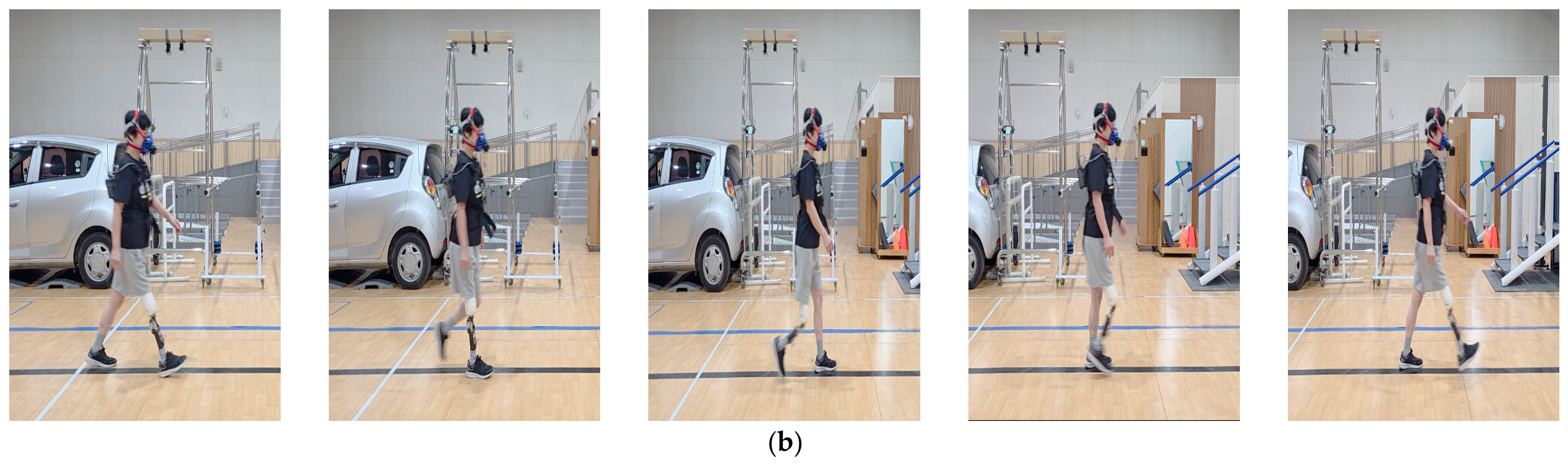
Metabolic energy efficiency was measured during a six-minute walk test (6MWT) using a portable respiratory gas analyzer (K4b2; COSMED, Rome, Italy). The test was performed on a level 100 m track to minimize the acceleration and deceleration associated with turning, and each prosthetic condition was walked at two self-selected paces, Normal and Fast.
Successive walking sessions were separated by at least 30 min of washout, and a session began only after real-time monitoring confirmed that heart rate and oxygen uptake had returned to the resting baseline, which limited any carry-over of fatigue. The two devices alternated in an OP5–ECPK–OP5–ECPK sequence, and within that sequence the three-minute confirmatory bouts always preceded the six-minute bouts used in the metabolic comparison (
Section 4.7). Bout duration was therefore fixed within the session sequence while device order alternated, leaving a residual ordering effect that is addressed in
Section 5.3. Condition could not be blinded, so expectation effects cannot be excluded; these are also considered in
Section 5.3.
Net oxygen cost was defined as the mean oxygen uptake over the final four minutes of walking (minutes 2–6), that is, after the initial oxygen-deficit phase and once the respiratory exchange ratio (RER) had stabilized. Resting oxygen uptake, measured during a 5 min seated rest before each test, was subtracted, and the difference was normalized to walking speed and body weight. Because it is expressed per unit body weight and distance, net oxygen cost permits comparison between the two conditions despite their different self-selected speeds. It does not, however, offset the ECPK’s ~400 g of added distal mass; the metabolic cost of that mass is reflected in the reported value rather than corrected out.
4.3. Real-Time Control Responsiveness
The real-time tracking performance of the ECPK control algorithm in response to changes in treadmill speed was assessed under a single-participant condition.
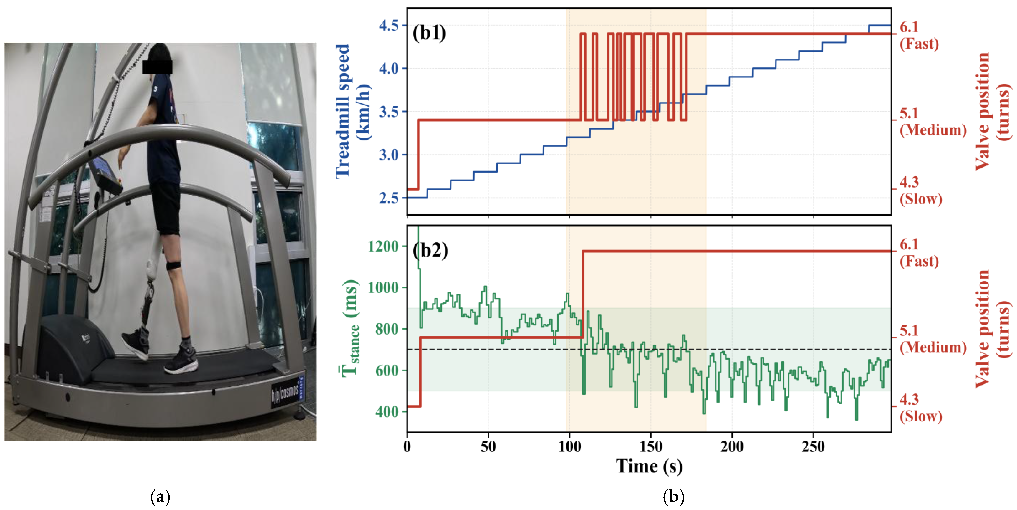
Figure 11 presents the time-series variation in treadmill speed and flexion valve position recorded synchronously while the participant performed a stepwise incremental protocol, in which treadmill speed was gradually increased from 2.5 km/h to 4.5 km/h in increments of 0.1 km/h every 15 s.
The results indicate that as walking speed increased, the system adjusted the valve position from Slow Mode (4.3 turns) to Medium Mode (5.1 turns) and then to Fast Mode (6.1 turns), consistent with the intended design in which falling stance time raises pneumatic damping. However, as shown in
Figure 11(b1), the valve position reversed 20 times over the protocol; two of these were the intended Slow → Medium and Medium → Fast changes, and the remaining 18 were spurious Medium ↔ Fast reversals concentrated in the 3.2–3.7 km/h band, where the two-step mean stance time repeatedly straddled the single 700 ms Medium–Fast boundary. These reversals produced the chattering and control oscillation observed for approximately 75 s (red lines).
Once the treadmill speed exceeded approximately 3.7 km/h, the oscillations stabilized and the system consistently maintained Fast Mode. We read this oscillation as a control-design limitation: near the mode boundaries, the participant’s normal stride-to-stride variability repeatedly crosses the algorithm’s single fixed threshold. In particular, the two-cycle moving average of
Section 3 does not sufficiently suppress the stance-time scatter near these boundaries. According to the participant’s subjective feedback, a mild sensory disturbance associated with frequent damping changes was perceived in this region, although it did not result in loss of kinematic support or falls. This boundary oscillation is a control-quality limitation of the fixed-threshold logic rather than a loss of support, and it motivated the revised decision logic described in
Section 3.2.
The revised logic was evaluated against the stance-time sequence recorded from the participant during the treadmill trial, which had been logged while the fixed-threshold logic was driving the valve. This measured sequence was played back through the controller running the revised firmware, so that the implemented decision logic, rather than a model of it, was exercised against the same stride-to-stride variability that had produced the oscillation. Under this input, the number of valve transitions over the 2.5–4.5 km/h protocol fell from 20 to two—the intended Slow → Medium change near 2.5 km/h and a single Medium → Fast change near 3.5 km/h—so that all 18 spurious Medium ↔ Fast reversals were removed. The Medium → Fast transition that remains within the former oscillation range is committed once, at approximately 3.5 km/h, at the first crossing of the widened upward switching threshold (500 ms). It is not reversed thereafter because, as walking speed continues to rise, the downward switching threshold (900 ms) is only rarely reached: the mode is held by the width of the band rather than by a monotonic fall in stance time. This point lies within the 3.2–3.7 km/h band over which the as-recorded system had chattered, so the single transition retained there is the intended mode change rather than oscillation.
Figure 11(b2) is an offline replay: the stance-time sequence recorded in
Section 4.3—logged while the fixed-threshold logic was driving the valve, so that the effect of the chattering on the participant’s gait is already embedded in the input—was played back through the implemented firmware. It shows that the revised logic suppresses the recorded stride-to-stride variability; it does not reproduce the closed-loop interaction by which a change in damping would alter the participant’s subsequent gait, and is therefore a design analysis rather than a re-validation with the participant walking.
4.4. Mode-Transition Behavior During Overground Walking
While the preceding treadmill experiment characterized the controller under imposed constant-speed conditions, this section reports a limited observation of the ECPK’s initial mode-transition responsiveness during self-paced overground walking in a single participant. The objective of this experiment is to determine whether the controller can detect variations in stance time and respond appropriately according to the predefined algorithm under real-world conditions.
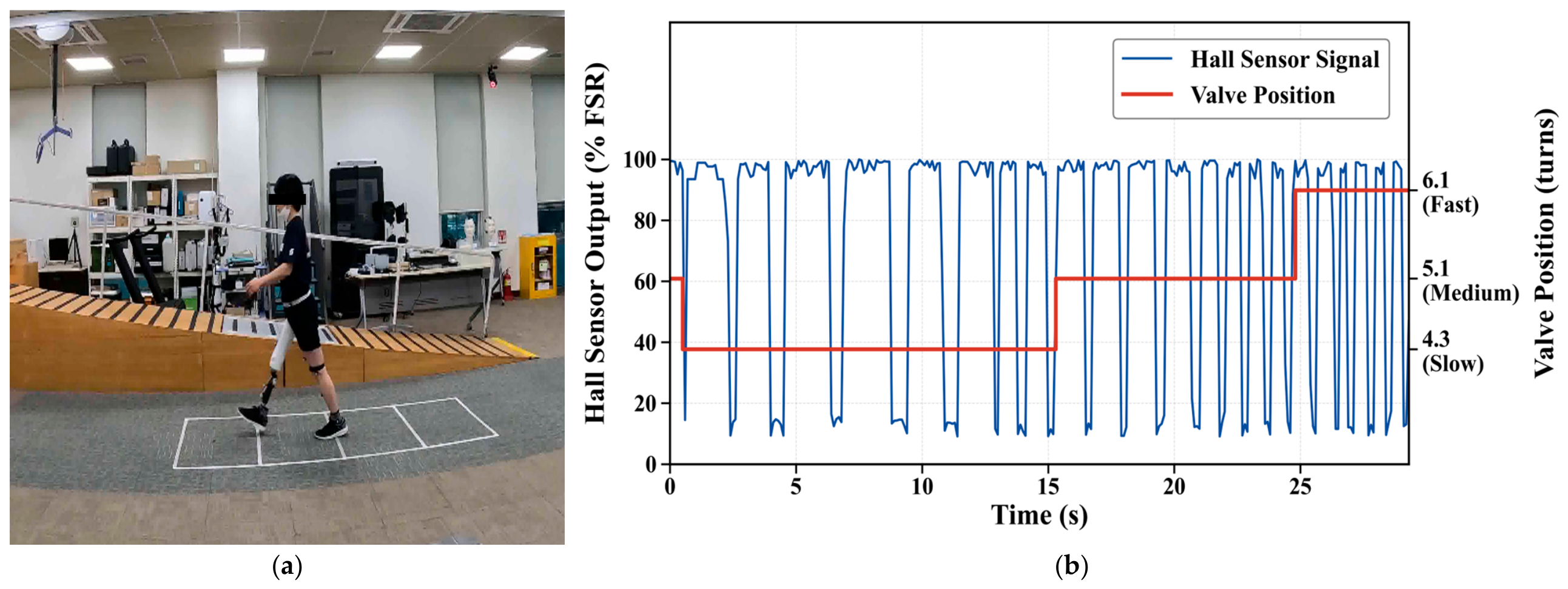
Figure 12 shows the continuously logged Hall sensor signal (input) and valve position data over approximately 30 s of level walking.
Examining the control trajectory in detail, the system remained in a standby state at the initial firmware setting of Medium Mode (5.1 turns) at the start of the experiment (t = 0 s). Shortly after the participant initiated walking from a stationary state (~0.5 s), the relatively long initial stance time was detected by the control system, and the algorithm immediately opened the valve to transition to Slow Mode (4.3 turns). This response follows the intended logic: the prolonged stance of the initial acceleration phase is read as a low walking speed, and damping is reduced accordingly. As the participant voluntarily increased step length and cadence, the interval between successive threshold crossings of the Hall signal shortened, and the system returned to Medium Mode (5.1 turns) at approximately 14 s. In the later phase, as walking speed further increased to a fast walking pace at approximately 26 s, the system exhibited a stepwise transition to Fast Mode (6.1 turns).
Within this single short overground trial, the controller adjusted damping in both directions. This trial was designed to confirm mode-transition behavior outside the treadmill environment, not to quantify tracking accuracy, which would require repeated trials with an independent speed reference (
Section 5.3).
4.5. Spatiotemporal Gait Parameters and Kinematic Symmetry
In the preceding control tracking evaluation, short-duration tests were conducted up to 4.5 km/h to verify the operational bandwidth of the control system. However, for the evaluation of kinematic symmetry and stability during continuous walking, the maximum speed was limited to 4.0 km/h to ensure participant safety. At speeds above 4.0 km/h the extension lag of a fixed orifice becomes more pronounced during swing, so continuous walking was capped at 4.0 km/h as a precaution. Toe clearance and knee angle at heel contact were not instrumented; this cap was therefore a precautionary limit rather than a measured threshold, and comparison between conditions above it was not attempted.
In this section, spatiotemporal parameters collected under treadmill conditions are analyzed. Walking speed was gradually increased from 2.5 km/h to 4.0 km/h. The evaluation conditions included a passive polycentric mechanical prosthesis with 15 years of habituation (Passive, OP5), a condition in which the electronic control was disabled and the flexion valve was held at the Medium-mode setting (5.1 turns) for all speeds (Fixed Orifice, FO), and a condition with real-time variable-orifice control using the proposed algorithm (Semi-active Variable Orifice, VO). FO and VO are therefore identical in mass, geometry and alignment, and differ only in whether the valve was re-commanded during walking. Because the FO setting coincides with the Medium Mode, the two conditions are physically identical at speeds for which the controller selects Medium (2.5 and 3.0 km/h in these trials); any difference observed there reflects trial-to-trial variability rather than the control strategy, and serves as a reference for the differences at higher speeds.
Table 8 summarizes step length and stance-phase ratio of both limbs under each speed and control condition. All values are reported as mean ± standard deviation (SD) over 10 consecutive gait cycles taken from a steady-state segment at each speed. Step lengths of both the intact and prosthetic limbs increased with walking speed under all three conditions. Across all speed conditions the intact limb consistently showed a higher stance-phase ratio (approximately 70–73%) than the prosthetic limb (approximately 57–60%), the load-avoidance pattern commonly reported in transfemoral amputee gait. This stance-phase ratio was similar across the three conditions, as expected, since the ECPK regulates swing-phase damping and does not act on stance-phase load bearing.
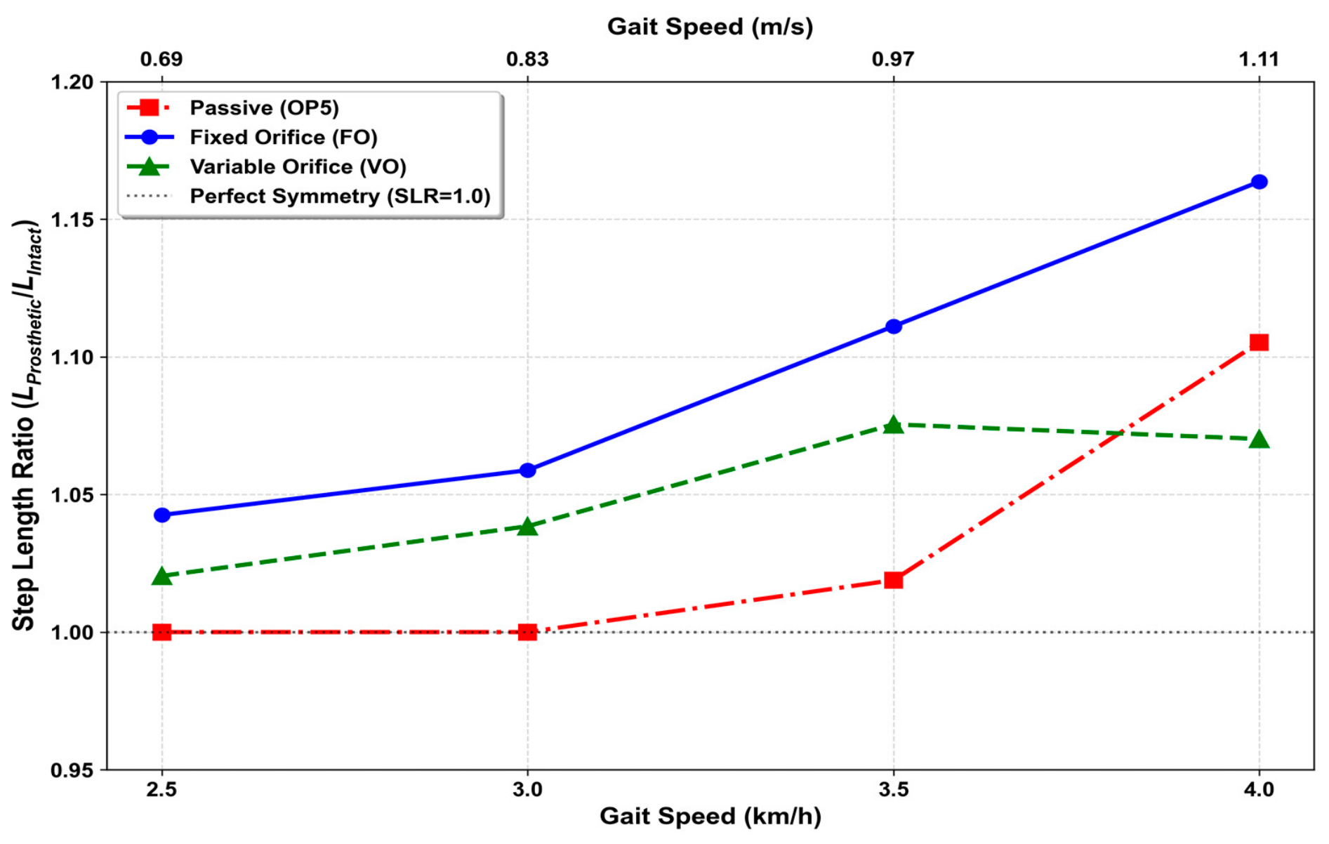
The left–right symmetry of step length is considered next. To quantitatively evaluate the speed adaptability of the proposed system from a kinematic perspective, the step length ratio (SLR) was calculated from average step length data and used for comparative analysis. The SLR is defined as shown in Equation (5); values closer to 1.0 indicate symmetric gait with balanced step lengths between the intact and prosthetic limbs.
Here, (intact step length) refers to the linear distance from the preceding prosthetic heel-strike point to the subsequent heel strike of the unaffected limb. (Prosthetic step length) refers to the linear distance from the preceding unaffected heel-strike point to the heel-strike of the prosthetic limb.
Figure 13 shows the mean SLR as a function of walking speed under the three conditions. The results indicate that the participant’s long-term adaptation strongly influenced performance in the lower speed range. At 2.5 and 3.0 km/h the OP5 condition gave an SLR of 1.000 at the reported precision, closer to unity than the FO condition (1.043 and 1.059) and the VO condition (1.020 and 1.038). This is consistent with gait patterns well adapted to the OP5 over 15 years of use, although the present data cannot separate device characteristics from long-term adaptation.
As walking speed exceeded 3.5 km/h, this long-term adaptation effect reached the mechanical limits of the system. Under the OP5 condition, the SLR rose to 1.105 at 4.0 km/h, indicating greater asymmetry. The FO condition showed a similar trend, with the SLR rising continuously to 1.164, attributed to the inability of the fixed damping setting to accommodate the increased inertial demands of high-speed walking. This is interpreted as a typical compensatory pattern in which prosthetic step length becomes disproportionately longer than that of the intact limb due to extension lag during the swing phase.
In contrast, under the VO condition the SLR was essentially unchanged between 3.5 and 4.0 km/h (1.075 and 1.070), a difference well below the stride-to-stride spread of the underlying step lengths, while the asymmetry of the other two conditions continued to increase over the same interval.
Although the VO condition did not match the low-speed symmetry of the long-term-adapted OP5, it showed a possible advantage at the higher speeds tested. In this single participant (N = 1), and despite a distal mass penalty of approximately 400 g, the VO condition was the only one of the three tested in which step-length asymmetry did not increase further at 4.0 km/h, the speed at which the two passive configurations (OP5, FO) showed their largest asymmetry.
4.6. Center-of-Pressure Behavior and Dynamic Stability
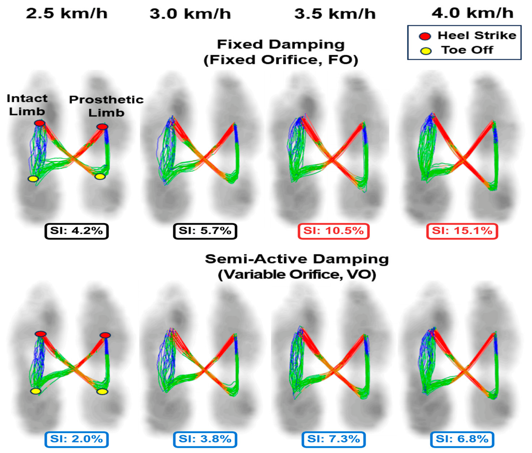
Beyond apparent kinematic symmetry at the spatiotemporal-parameter level, the dynamic center-of-pressure (COP) trajectory was analyzed to evaluate ground-reaction-force distribution and load transfer. Two independent indices are reported: (b1) the COP butterfly diagram, a qualitative morphological visualization of the COP trajectory, and (b2) the symmetry index (SI) proposed by Robinson et al. [
57], computed here from step-length data and defined in Equation (6). The SI is presented alongside, but is not derived from, the COP butterfly trajectories.
Here,
and
represent the measured value of the gait variable for the intact and prosthetic limbs, respectively. The symmetry index equation is that of Robinson et al. [
57]; the ~10% band used here to describe acceptable symmetry is a common convention associated with the index rather than a formal cutoff proposed in [
57], and is used for description only. This threshold is used here for description only, not as a diagnostic criterion.
Figure 14 presents COP butterfly trajectories and SI values under each speed and control condition. At 2.5 km/h and 3.0 km/h, both the fixed-damping condition (FO) and the variable-damping condition (VO) remained below the 10% reference value. As walking speed increased to 4.0 km/h, the butterfly trajectory under the FO condition became visibly distorted and the SI rose to 15.1%. Under the variable-damping condition (VO), the SI was 6.8% at the same speed, with a more symmetric trajectory than under FO. For reference, the SI computed from the OP5 step lengths in
Table 8, a condition not shown in
Figure 14, was 0% at 2.5 and 3.0 km/h, 1.9% at 3.5 km/h, and 10.0% at 4.0 km/h.
To characterize the load-transfer behavior accompanying this symmetry result, stride length, COP path symmetry, and maximum COP velocity were extracted across the same speed range and summarized in
Table 9. Stride length increased with walking speed under both conditions, and at the highest tested speed (4.0 km/h) it reached 119 cm under FO and 118 cm under VO, so that the same treadmill speed was covered with essentially the same stride length in the two conditions. COP path symmetry and maximum COP velocity showed no consistent difference between FO and VO either, the two conditions alternating in rank from one speed to the next rather than separating systematically. This near-absence of a between-condition difference is expected rather than anomalous, because stride length, COP path symmetry, and stance-phase loading are governed by the four-bar linkage together with the shared socket, pylon, and foot, none of which differs between FO and VO, whereas the variable-orifice controller acts only on swing-phase damping and therefore leaves these stance-dominated measures largely unchanged.
Maximum COP velocity increased with walking speed under both conditions and did not separate systematically between them, the FO condition being higher at 2.5 and 3.0 km/h, the VO condition being higher at 3.5 km/h, and the two conditions falling within 0.1 cm/s of each other at 4.0 km/h (FO 165.5 cm/s versus VO 165.4 cm/s). Maximum COP velocity is in any case an ambiguous index in the present context, since a higher value is read as reduced postural stability under conventional static-balance criteria but may instead reflect maintained forward propulsion during dynamic level-ground walking, and the single-session data cannot distinguish between these readings. The prosthetic-side vertical loading-response peak was similarly close between the two conditions at 4.0 km/h (FO 512 N versus VO 515 N), which is consistent with stance-phase load bearing being set by the shared linkage and components rather than by the swing-phase controller. Taken together, these COP and loading measures do not by themselves establish any difference in dynamic stability between FO and VO, and the margin of stability, joint moments, trunk acceleration, and three-axis ground-reaction forces that would be needed to establish one are left to future work. The effect attributable to variable-orifice control appears instead in swing-phase step-length symmetry, reported in
Section 4.5 and
Figure 14, where the symmetry index at 4.0 km/h is held at 6.8% under VO against 15.1% under FO.
4.7. Evaluation of Metabolic Energy Efficiency and Gait Performance
As the final evaluation in this study, a six-minute walk test (6MWT) was conducted on level ground to assess the gait assistance effectiveness of the ECPK system from a physiological perspective. Because the two conditions were compared at self-selected rather than matched speeds, the metabolic values reported in this section are descriptive; see
Section 5.3 for the methodological caveats. The participant wore a portable respiratory gas analyzer (K4b
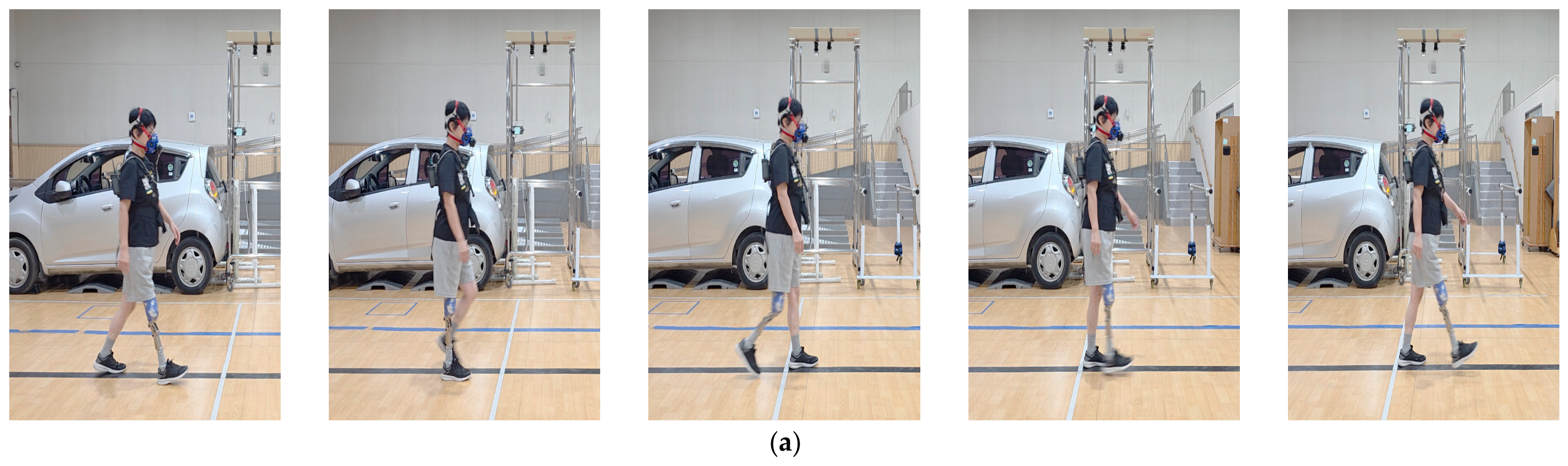
2 COSMED, Italy) during the test. The experimental setup and participant instrumentation are shown in
Figure 15.
The control condition was defined as the passive polycentric mechanical prosthesis (Össur OP5) that the participant had used for 15 years with a high degree of adaptation. The experiment was conducted under two conditions: the participant’s self-selected Normal Walking speed (which activates Medium Mode in the controller) and a fast walking speed. The primary outcome measure was net oxygen cost, which represents walking economy, calculated using Equation (7).
Here,
represents the mean oxygen uptake (mL/min) measured during walking, and
represents the oxygen uptake measured during a seated rest condition prior to the test. Walking speed was expressed in m/min, and body weight in kg.
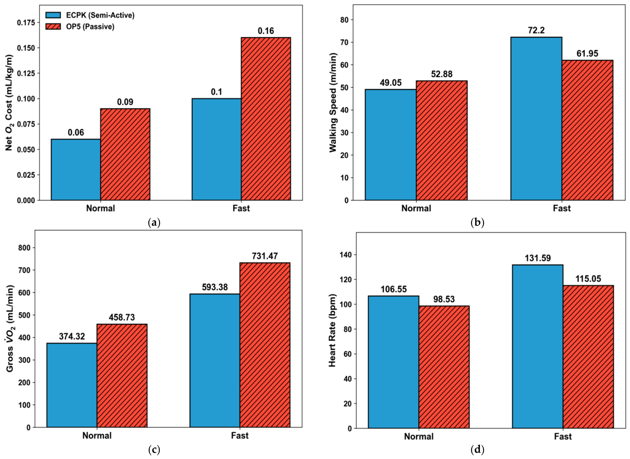
Figure 16 and
Table 10 present the quantitative comparative analysis of physiological gait parameters obtained from the 6MWT.
Analysis of the clinical metrics six-minute walk distance (6MWD) and walking speed showed that under the Normal condition, total walking distance (317.30 m) and speed (52.88 m/min) were greater under the OP5 condition than under the ECPK condition (294.30 m; 49.05 m/min). This may reflect long-term habituation to the OP5 together with a conservative gait strategy adopted in response to the unfamiliar control and the added distal mass of approximately 400 g; the present design cannot separate these contributions. In contrast, under the Fast condition, the ECPK achieved a 6MWD of 433.20 m at 72.20 m/min, whereas the OP5 reached 371.70 m at 61.95 m/min. This corresponds to an approximately 16.5% greater walking distance with the ECPK under the Fast condition—a reversal of the Normal-condition direction that is consistent with the passive damper approaching its mechanical limits at higher speed, although a single-case comparison cannot establish the cause.
For heart rate, a higher value was observed under the Fast condition with the ECPK (131.59 bpm) compared with the OP5 (115.05 bpm). This increase cannot be attributed solely to the added hardware mass. Under the same condition the participant reached an RER of 1.13 with the ECPK, compared with 1.04 for the OP5. An RER at or above 1.10 is conventionally read as evidence of maximal effort, while an appreciable anaerobic contribution is already present once RER approaches 1.0 [
58]; both Fast conditions therefore lie at or above that point, the ECPK condition more so. The participant increased voluntary walking speed to a near-maximal 72.20 m/min under the ECPK, which in turn elevated cardiovascular demand; the present measures do not allow this to be attributed to greater confidence or perceived stability.
Gross oxygen uptake under the Fast condition was itself lower with the ECPK (593.38 mL/min) than with the OP5 (731.47 mL/min), although the ECPK condition was walked faster, with approximately 400 g more distal mass and at a higher heart rate. Taken together with the elevated RER, this pattern is consistent with an anaerobic contribution that indirect calorimetry does not capture.
Despite the elevated cardiovascular demand, net oxygen cost, the primary metabolic outcome, was 37.5% lower with the ECPK, uncorrected for that anaerobic contribution. These findings rest on a preliminary single-participant observation and their generalizability is therefore limited. One possible explanation for the direction observed is that speed-adaptive damping reduced compensatory movement during high-speed walking. Given the unmatched speeds and the near-maximal effort reached under the ECPK, this remains a hypothesis to be tested under the matched-speed protocol described in
Section 5.3.
The same direction was observed in the shorter three-minute confirmatory bouts, in which the ECPK showed a lower net O2 cost than the OP5 at both the Normal and the Fast pace. These bouts are not tabulated with the primary results because they do not contain the minutes 2–6 steady-state window used here and, under the Fast condition, reached an RER of 1.28; they therefore indicate only that the direction of the difference was reproduced, not its magnitude.




 ,
,