Article

Multi-Objective Taguchi-FEM Optimization and Prototype-Based Verification of a Permanent Magnet Mechanical Clutch


1
Department of Mechanical Engineering, Cheng Shiu University, No. 840, Chengching Rd., Niaosong District, Kaohsiung 83347, Taiwan
2
Department of Industrial Engineering and Management, Cheng Shiu University, No. 840, Chengching Rd., Niaosong District, Kaohsiung 83347, Taiwan
*
Author to whom correspondence should be addressed.
Appl. Sci. 2026, 16(11), 5363; https://doi.org/10.3390/app16115363
Submission received: 22 April 2026 / Revised: 19 May 2026 / Accepted: 21 May 2026 / Published: 27 May 2026

Featured Application

The optimized permanent magnet mechanical clutch developed in this study provides a high-efficiency solution for torque transmission and decoupling in industrial and automotive systems. Specific applications include industrial automation, such as packaging conveyor belts and automatic paper feed mechanisms in photocopiers. Due to its non-contact operation and superior heat dissipation compared to traditional electromagnetic clutches, it is also ideal for harsh operating conditions requiring a maintenance-free, extended lifespan.

Abstract

This study evaluates a preliminary multi-objective optimization framework for a permanent magnet mechanical clutch designed for automated curtain actuators. To analyze the highly non-linear trade-off between disengagement capability (Y-direction magnetic resistance) and positional stability (Z-direction magnetic attraction force), a numerical approach combining three-dimensional (3D) magnetostatic finite element method (FEM) simulations, Taguchi L9 orthogonal arrays, and regression modeling was implemented. Three magnetic bead diameters were introduced as noise factors to investigate the sensitivity of the magnetic forces within a controlled simulation environment. A multiplicative composite objective function was employed to assess the competing performance criteria without masking single-factor failures. Statistical analysis indicates that within the investigated design space, the axial distance (Factor D) is the primary geometric parameter influencing the force distributions, followed by the outer diameter (Factor B) and inner diameter (Factor A). The identified parameter configuration (A = 8 mm, B = 10.5 mm, C = 0.5 mm, D = 1.5 mm) demonstrated an improved composite objective value and narrower standard deviations under the designated simulation boundaries compared to the initial discrete trials. These exploratory findings suggest that the proposed workflow was validated using a physical prototype based on one of the Taguchi configurations.

1. Introduction

Permanent magnet (PM) transmission devices, such as couplers and clutches, play a pivotal role in modern industry and precision machinery owing to their distinct advantages, including non-contact transmission, wear-free operation, elimination of lubrication, and overload protection [1,2]. Particularly in applications such as motorized curtains and small-scale automated actuators, achieving highly efficient power switching remains a critical research focus [3,4]. However, a significant research gap remains in the quantitative design of PM clutches that achieve engagement and disengagement solely through mechanical structures and centrifugal forces, without relying on electromagnetic field control.
The existing academic literature predominantly focuses on electromagnetic clutches [1,2,4,5,6,7,8] or magnetorheological (MR) clutches [9,10,11,12,13,14,15]. Although electromagnetic clutches offer rapid response and precise control, they require a continuous power supply to maintain the magnetic field, and the resulting coil heating constrains their performance and operational lifespan [16,17]. On the other hand, MR clutches regulate torque by modulating fluid viscosity; however, they face persistent challenges, including sealing failures and particle sedimentation [18,19]. Consequently, for small-scale devices that prioritize energy conservation and structural simplification, these systems, which depend on external power supplies, are far from optimal [4].
Compared to academic papers, designs for purely mechanical PM clutches are primarily documented in the patent literature [3,20,21,22,23,24,25,26]. Most of these patents utilize centrifugal forces, spring biasing, or cam mechanisms to guide the displacement of magnetic components. For instance, Wang [3,24] proposed an inclined outer wall and concave shell design to achieve switching between manual and electric modes, while Gao [23] employed the magnetic attraction between slider blocks and magnetically permeable components to enhance stability. Despite the creativity of these designs, their descriptions remain largely qualitative [3,25], focusing predominantly on the principles of operation with little to no quantitative data regarding air-gap magnetic field distribution, dynamic return torque, or the engagement process. This lack of certainty hinders developers from accurately predicting clutch behavior under specific loads.
To enhance product performance, finite element analysis (FEA) has emerged as a crucial tool [1,5]. Utilizing software such as ANSYS Maxwell or COMSOL, researchers can predict air-gap magnetic field intensity and magnetic flux density distributions [24,27]. Previous studies indicate that the “detent effect” in PM equipment leads to thrust or torque ripples, which necessitate optimization through geometric modeling [1]. For mechanical clutches, simulations must integrate dynamic models that account for the dynamic equilibrium between centrifugal forces and magnetic attraction—a domain where research into “rapid return” characteristics is currently most deficient [28].
Clutch design often involves conflicting objectives: achieving a “rapid return” requires a stronger return spring or higher magnetic gradient density, which can inevitably compromise the sensitivity of “centrifugal engagement” [28,29]. Therefore, the incorporation of multi-objective optimization is of paramount importance. In recent years, researchers have begun applying the Non-dominated Sorting Genetic Algorithm II (NSGA-II) [5], the Taguchi method [27], or neural networks [29] to resolve these complex, non-linear relationships. For example, Andriushchenko et al. [5,27] demonstrated the efficacy of these methods in balancing torque enhancement and structural compactization, while Zhang [29] significantly reduced simulation optimization time through the use of neural networks.
In summary, several distinct research gaps exist for purely mechanical PM clutches. First, a clear deficiency remains in quantitative research, particularly concerning comprehensive mathematical modeling and performance benchmarks. Furthermore, the engagement and return processes are frequently neglected because the majority of existing studies focus predominantly on static torque and fail to account for the dynamic equilibrium during these critical transient phases.
Conventional gear motors employed in motorized curtains generally operate at low rotational speeds of merely 30 to 100 rpm. Therefore, facilitating the reliable engagement of magnetic beads into the output ring under these low-speed conditions, while ensuring their prompt disengagement when the motor halts, emerges as a critical design imperative. This study proposes a multi-objective optimization framework to improve both rapid return and centrifugal engagement in a permanent magnet mechanical clutch. Maxwell-based electromagnetic simulation and a Taguchi L9 design of experiments were employed to analyze four geometric parameters: inner radius, outer radius, washer thickness, and axial distance. A composite objective function, using S/N normalization and multiplicative synthesis, enables simultaneous enhancement of magnetic resistance and attraction force. Main effects analysis, ANOVA, and regression modeling identify key design factors and validate an optimized configuration that is more robust and balanced dynamically.

2. Materials and Methods

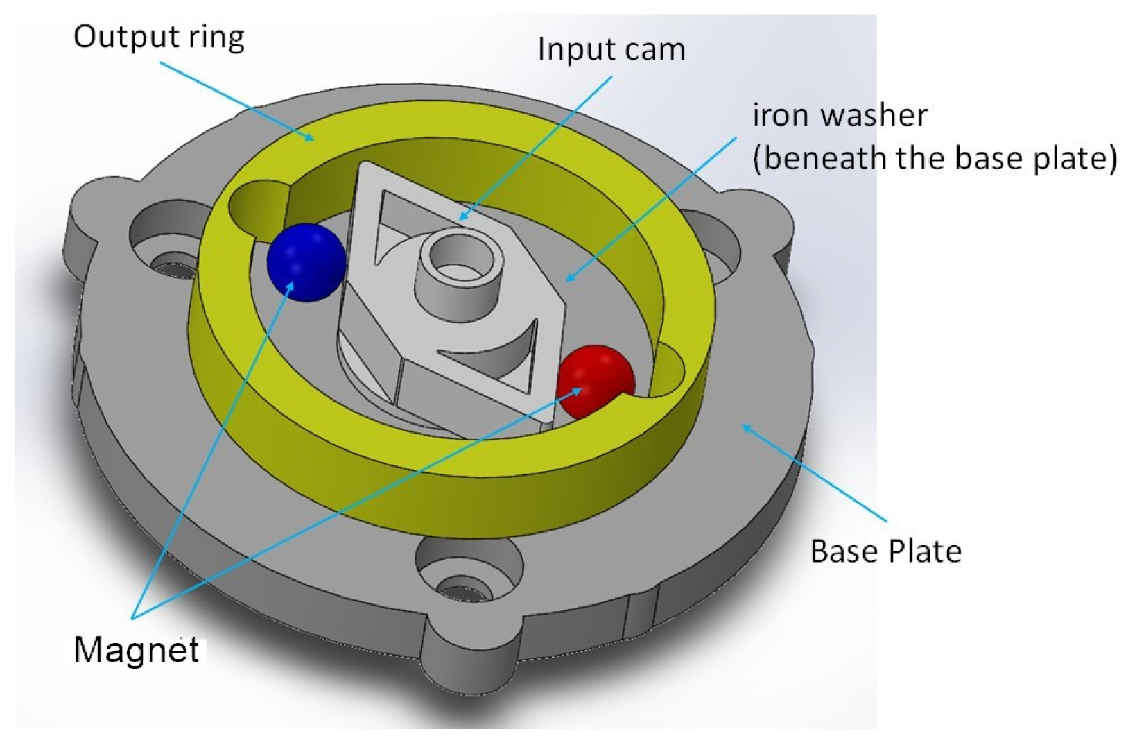
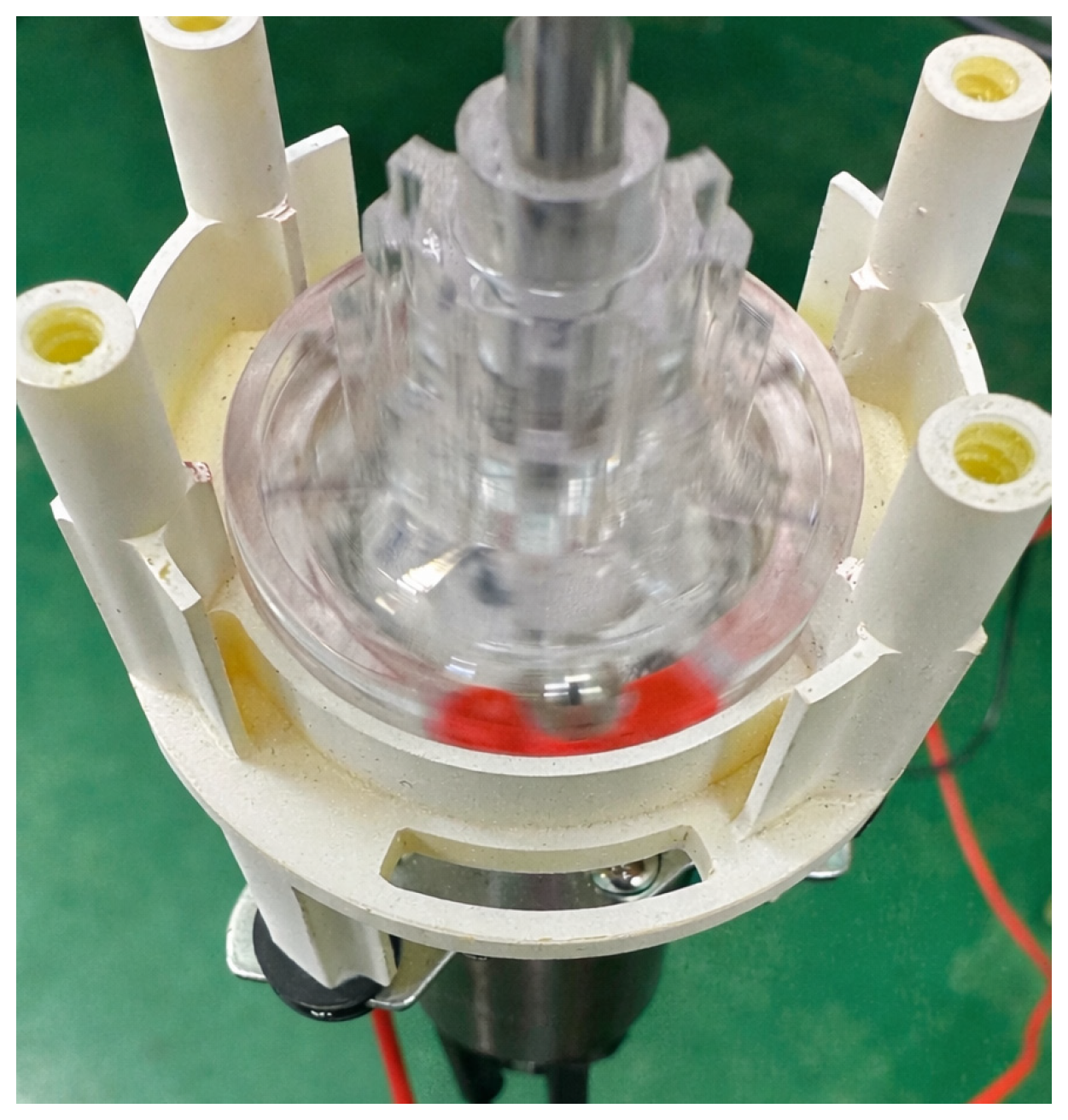
This research refers to a permanent magnet mechanical clutch, primarily composed of (1) an POM input cam, (2) two N35 magnetic beads, (3) an iron washer, (4) an POM output ring, and (5) a POMbase plate. Its 3D CAD model is shown in Figure 1. The prototype is depicted in Figure 2.

2.1. Theoretical Derivation of the Minimum Energy Position of Magnetic Force

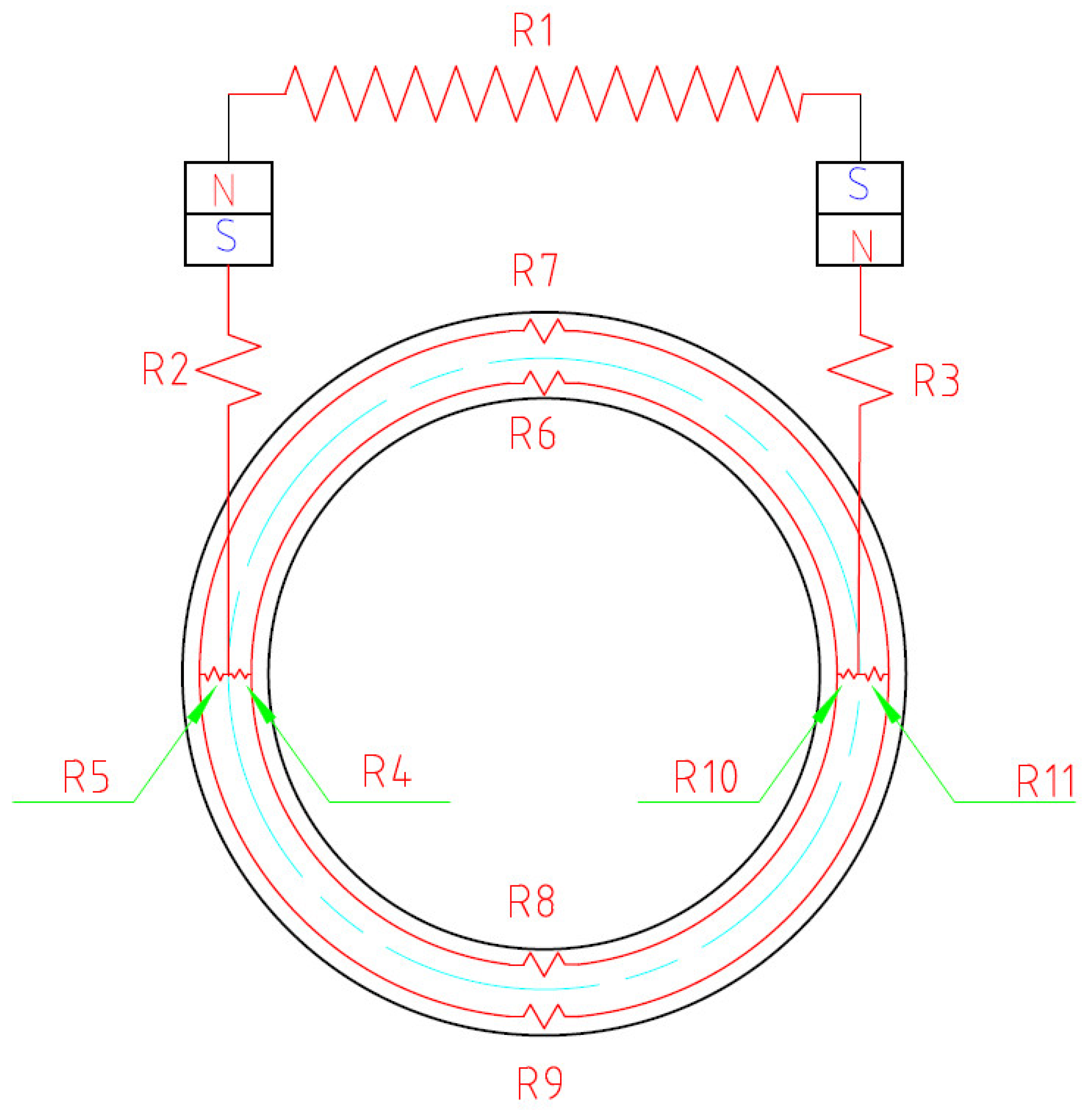
Figure 3 shows the magnetic circuit model of a permanent magnet clutch. The magnetic flux from the north pole of the left magnet passes through the perpendicular air gap d between the magnet and the magnetic ring. It then splits along the centerline of the magnet, flowing outward toward the outer diameter and inward toward the inner diameter, respectively. Finally, it traverses another perpendicular air gap d to reach the south pole of the right magnet.
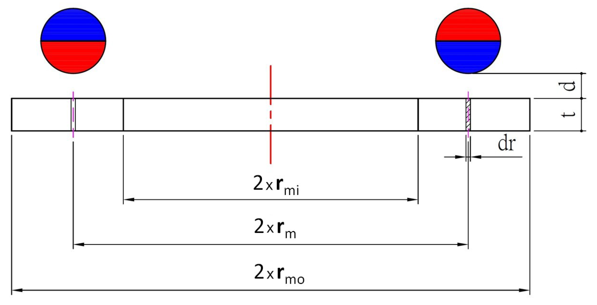
Since the magnetic flux generated by the magnetic bead closes both inward and outward, the structure can be viewed as two parallel magnetic circuits, as shown in the equivalent circuit diagram (Figure 3). The initial equilibrium position of the magnetic bead in the radial direction is essentially determined by the relative balance between the inner radial magnetic resistance (R4/R10) and the outer radial magnetic resistance (R5/R11). To quantitatively derive the equilibrium position of the magnetic bead, this study examines the interior of the iron washer, considering a thin cylindrical layer with radius r, radial thickness dr, and axial thickness t. In this case, the cross-sectional area perpendicular to the radial magnetic flux is the lateral surface area of the cylinder (A = 2πrt), while the radial magnetic path length corresponds to the thickness of the microelement (dL = dr). Their geometric topological relationship is shown in Figure 4. According to the principle of maximum magnetic permeability (minimum magnetic resistance) proposed by Roters [30], the magnetic bead will spontaneously stabilize at the equilibrium position where the total magnetic permeability (P) is maximized. It must be noted that this 1D analytical derivation is intended to provide a basic physical intuition and serve as an exploratory guideline for macroscopic design. Therefore, under the idealized assumptions of uniform magnetic permeability and neglecting leakage flux and edge effects, the governing equation for the element’s magnetic permeability (dP) can be expressed as follows:
The derivation of the elementary magnetic permeance (dP) follows the standard definition of magnetic resistance (reluctance, R) for a flux path of length L and cross-sectional area A in a medium with permeability μ, which is R = L μ A . In our model, we consider an infinitesimal cylindrical shell within the iron washer. Since the magnetic flux is assumed to flow radially, the path length dL corresponds to the infinitesimal radial thickness (dr), and the area A perpendicular to this flux is the lateral surface area of the cylinder (2πrt). The differential magnetic resistance (dR) is therefore: d R = d r μ · ( 2 π r t ) . Given that magnetic permeance (P) is the reciprocal of magnetic resistance (P = 1/R), the elementary permeance (dP) is derived as below.
d P = 1 d R = μ × ( 2 π r t ) d r
The magnetic resistance Ri of the inner ring section ranges from rmi to r:
R i = r m i r d r μ × ( 2 π r t ) = 1 2 π μ t l n r r m i
The resistance Ro of the outer ring section, ranging from r to rmo:
R o = r r m o d r μ × ( 2 π r t ) = 1 2 π μ t l n r m o r
Let k = 2πμt, the total magnetic permeability function is defined as shown below:
P ( r ) = P i + P o = k 1 l n r r m i + 1 l n r m o r
The equilibrium position occurs at the Extremum of P(r), i.e., when d P ( r ) d r = 0 :
r = r m i · r m o
It should be emphasized that the analytical formulation derived above (Equations (1)–(4)) operates under several idealized assumptions, including uniform magnetic permeability, negligible flux leakage, and omitted fringing effects. Consequently, these closed-form equations are intended strictly as an exploratory guideline to provide fundamental physical intuition and steer the initial design direction. To fully account for the realistic non-linear electromagnetic behaviors—such as magnetic saturation within the iron core, multi-directional flux leakage, and complex geometric fringing—high-fidelity 3D Maxwell Finite Element Method (FEM) simulations are systematically employed in the subsequent sections to achieve accurate quantitative predictions and optimization.

2.2. Three-Dimensional Magnetostatic Finite Element Analysis

To quantitatively evaluate the conflicting magnetic forces within the permanent magnet mechanical clutch and validate the exploratory 1D analytical trends, a three-dimensional (3D) numerical simulation framework was constructed using the Ansys Maxwell 2024 R1 FEM software suite. The simulation was conducted under magnetostatic conditions to determine the Y-direction magnetic resistance and the Z-direction magnetic attraction force of the magnetic beads at different positions.

2.2.1. Geometric Modeling and Simulation Domain Setup

The 3D CAD assembly of the clutch mechanism—consisting of two permanent magnetic beads (NdFe35) and an iron washer (Steel_1008)—was built using the Maxwell 2024 R1 Modeler environment. The coupling interface between the beads and the active tracking zones was defined by two cylindrical air gaps, each measuring 10 mm in diameter and 8 mm in height. To represent an open environment and contain the fringing and leakage fields, a virtual air bounding box was established as the solution domain. The domain boundaries were configured with an explicit offset percentage of 100% relative to the maximum bounding box of the physical clutch assembly. A zero-tangential magnetic vector potential boundary condition (Az = 0) was applied on the outer surfaces of this air domain to eliminate potential boundary truncation errors.

2.2.2. Material Properties

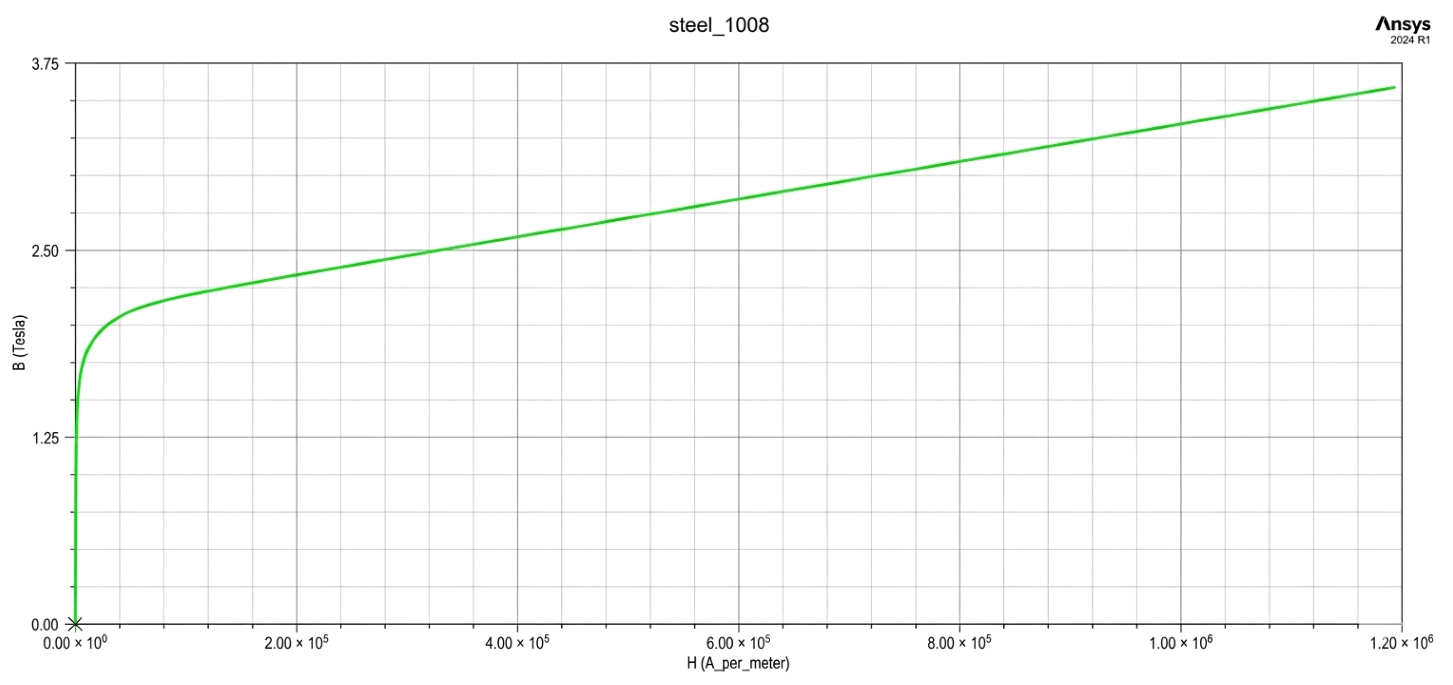
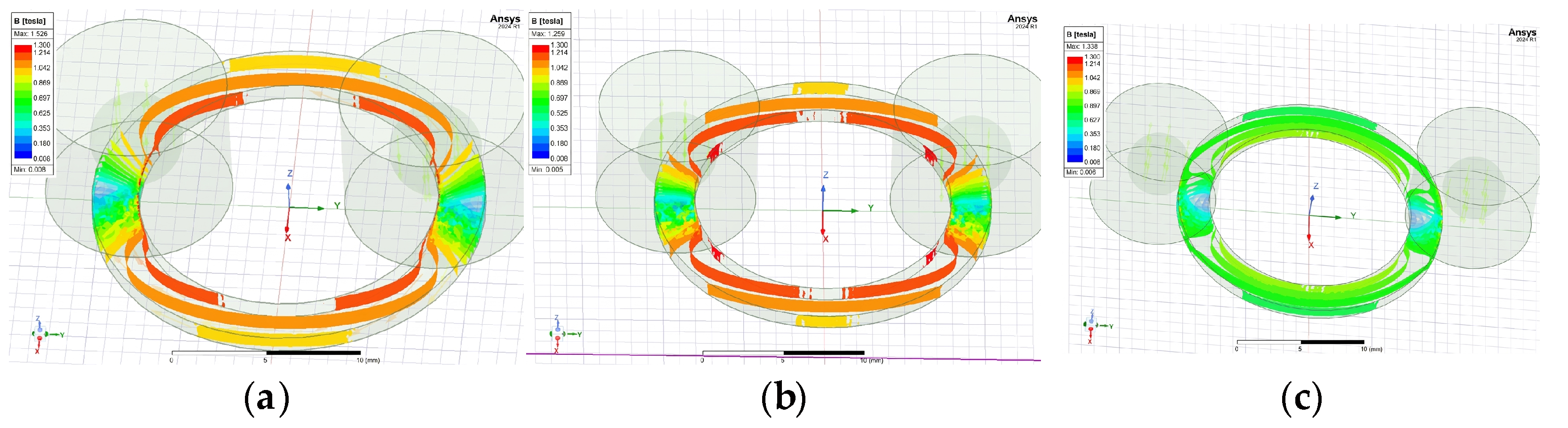
The electromagnetic material properties used in the magnetic circuit simulation were configured according to the parameters specified in Table 1. The two permanent magnetic beads were modeled as Grade NdFe35 sintered NdFeB magnets, with a magnetic remanence (Br) of 1.23 T and a coercive force (Hc) of 890 kA/m assigned along their designated magnetization axes. To account for localized magnetic saturation effects under flux concentrations, the non-linear B-H magnetization curve of Steel_1008 was explicitly mapped into the material library for the iron washer as shown in Figure 5. For one set of conditions, with d = 1.5 mm and t = 1 mm the magnetic beads were positioned at IR, at the theoretically calculated maximum magnetic permeability, and at a radius of 12.5 mm (greater than the outer diameter of the magnetic ring); the magnetic flux density distribution is shown in Figure 6.

2.2.3. Parameterization and Multi-Objective Optimetrics Analysis

To explore the multi-factor design space derived from the Taguchi L9 orthogonal array, the geometric dimensions of the iron core and assembly clearances were parameterized within the Maxwell design properties. Specifically, the spatial coordinate offsets governing the radial displacement of the magnetic beads across the ϕ10 mm × 8 mm cylindrical air gap regions were assigned as design variables. Utilizing the integrated Optimetrics evaluation engine, a series of parametric sweeps was executed from Outer radius to inner radius. For each discrete geometric combination, post-processing calculations utilized the virtual displacement method derived from the principle of virtual work to extract the static Y-direction magnetic resistance force and the static Z-direction magnetic attraction force.

2.3. Multi-Objective Optimization Procedure

In this study, we followed the below procedure:
  • The design target for magnetic resistance in the Y-direction is set to Smaller-the-Better. This ensures the magnetic sphere can overcome resistance smoothly during the driving process to achieve displacement, preventing stalling due to excessive resistance that could disrupt the normal operation of the clutch mechanism.
  • The magnetic attraction force in the Z-direction is set to “Larger-the-Better.” A higher magnetic attraction force increases the contact normal force, thereby enhancing friction. This promotes a pure rolling state for the magnetic bead, reduces sliding wear, and contributes to extending the clutch’s service life.

Steps for Multi-Objective Optimization

Step 1: Performing a Taguchi design and evaluating multiple responses.
A Taguchi L9 orthogonal array was employed to systematically arrange the simulation experiments involving four control factors—the inner radius of the iron washer (A: rmi), the outer radius (B: rmo), the washer thickness (C: t), and the axial distance (D: d)—each at three levels. For each experimental run, Maxwell simulations were conducted under three magnetic bead diameters (ϕ4.8, ϕ5.0, ϕ5.2), thereby generating three replications for each response. The three magnetic bead diameters were selected to represent the nominal dimension and practical manufacturing tolerance variation. The factor levels were selected based on the geometric constraints of the clutch structure, preliminary simulation screening, and practical manufacturability considerations to ensure stable assembly and magnetic interaction behavior. Two performance characteristics were evaluated: Y-direction magnetic resistance (Y), defined as Smaller-the-Better, and Z-direction magnetic attraction force (Z), defined as Larger-the-Better. The experimental layout and raw response values are reported in Table 2, where each response includes three replications (Y1–Y3 and Z1–Z3). This experimental design enhances robustness against geometric uncertainty arising from variations in magnetic bead diameter while preserving the orthogonality of the experimental matrix.
Step 2: Converging multiple responses into one objective function (OBJ).
To integrate the two conflicting objectives into a single optimization index, a signal-to-noise (S/N)-based normalization and multiplicative synthesis strategy was adopted. First, the average value, standard deviation, and S/N ratio were calculated for each response according to Taguchi quality characteristics, where the Y-direction magnetic resistance follows the Smaller-the-Better criterion and the Z-direction magnetic force follows the Larger-the-Better criterion. The S/N ratios of both responses were subsequently normalized into the range [0,1], denoted as Yn and Zn, respectively. The overall objective function (OBJ) was then defined as OBJ = Yn × Zn. This multiplicative formulation ensures that only experimental conditions performing well in both objectives can achieve a high composite score. Compared with linear weighted aggregation, multiplicative synthesis penalizes imbalanced performance more strictly, which is more suitable for ensuring robustness under dual-objective constraints. The multiplicative synthesis strategy was intentionally adopted to avoid selecting solutions with excellent performance in only one response while exhibiting unacceptable degradation in the other response. The complete calculation procedure and resulting OBJ values are summarized in Table 3, which shows that Experiments 2, 6, and 7 exhibit relatively balanced performance, whereas Experiments 8 and 5 are dominant in only one objective, resulting in near-zero composite performance.
Step 3: Creating the main effects plot and ANOVA table.
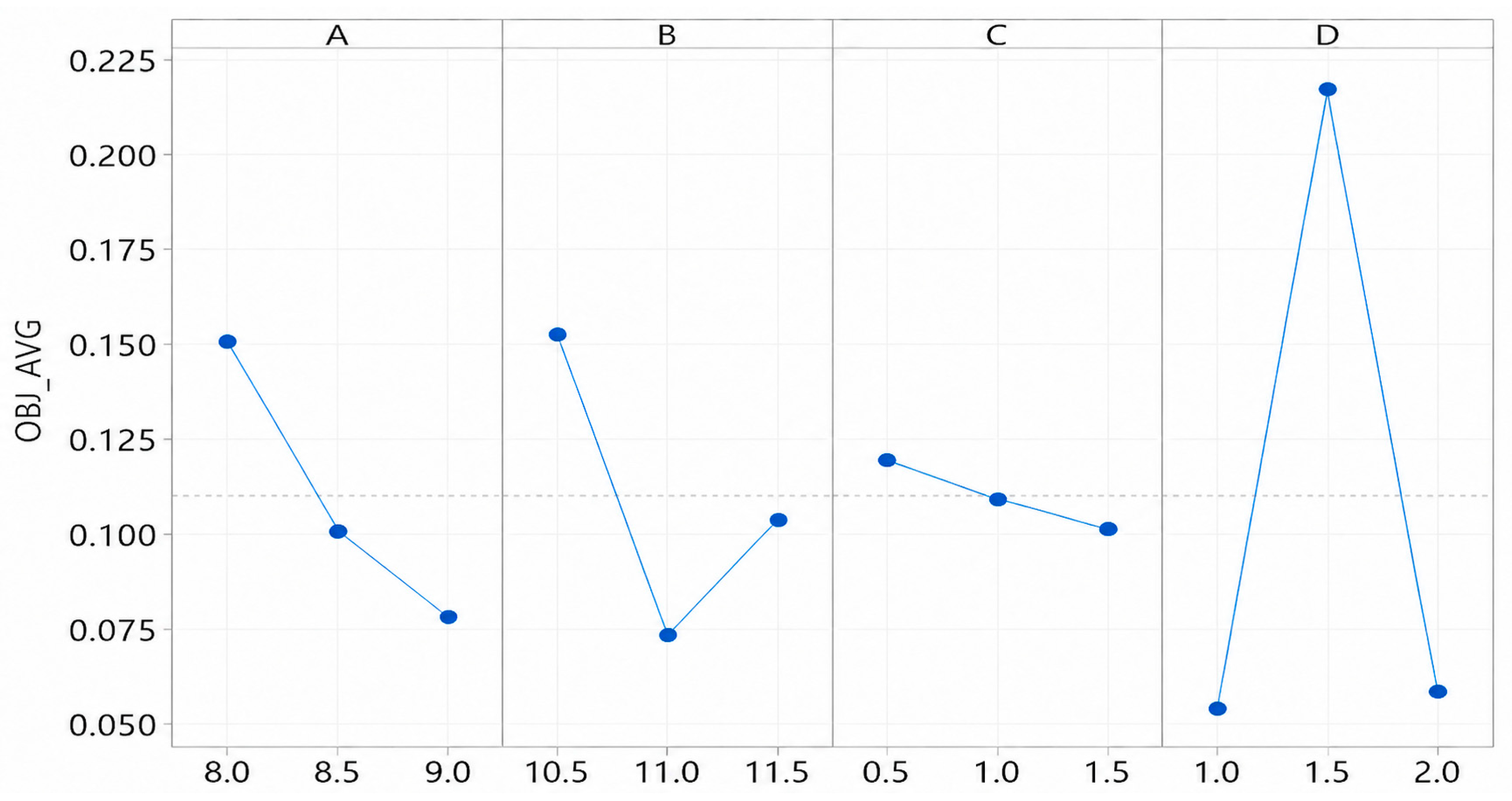
Based on the synthesized OBJ values, main effect plots were generated to visually examine the influence trends of each factor (Figure 7). The results indicate that factor D (distance d) exhibits the most significant variation across levels, followed by factor B (outer radius rmo) and factor A (inner radius rmi), whereas factor C (thickness t) contributes only marginally. To quantitatively validate these trends, an analysis of variance (ANOVA) was conducted. The ANOVA results (Table 4) confirm that factor D is statistically significant (p = 0.009), factor B is marginally significant (p = 0.049), and factor A shows moderate influence (p = 0.056). These findings indicate that axial distance (d) plays a dominant role in determining the trade-off performance between magnetic resistance and magnetic attraction, which is consistent with the physical mechanism of magnetic flux concentration in the clutch structure. Given the limited degrees of freedom inherent in the Taguchi L9 design, ANOVA is used here as an exploratory statistical tool rather than for strict hypothesis testing. Factor C (washer thickness) exhibited a relatively minor effect in the main-effects analysis and was therefore pooled into the error term to provide residual degrees of freedom for exploratory ANOVA evaluation. Nevertheless, due to the saturated nature of the L9 design, the present statistical analysis should be regarded as preliminary trend identification rather than rigorous inferential validation. Additional confirmation experiments and interaction analysis, particularly for potential C × D interactions, will be considered in future work.
Step 4: Creating and optimizing the general linear model of OBJ.
A general linear model (GLM) was constructed using the categorical factor formulation based on the Taguchi experimental structure. The regression equation for OBJ is expressed as
O B J = 0.11 + 0.04087   A _ 8 0.00913   A _ 8.5 0.03173   A _ 9 + 0.04257   B _ 10.5 0.03637   B _ 11 0.00620   B _ 11.5 0.05603   D _ 1.0 + 0.10743   D _ 1.5 0.05140   D _ 2.0
The model demonstrates excellent goodness of fit, with R2 = 99.30%, adjusted R2 = 97.22%, and predicted R2 = 85.91%, indicating strong explanatory and predictive capability. Although the R2 value is high due to the saturated categorical model and limited experimental runs, the model is primarily used for factor-level trend interpretation rather than prediction. Therefore, the regression model should be interpreted primarily as a trend-identification tool rather than a highly generalized predictive model. Based on the regression coefficients, the optimal factor-level combination for maximizing OBJ is identified as A = 8, B = 10.5, and D = 1.5.

3. Results

This section is divided into two parts. The first part uses an example to illustrate the previously mentioned minimum energy position of the magnetic bead. The second part employs the parameters identified through the aforementioned multi-objective optimization to conduct verification experiments and compare their results.

3.1. Minimum Energy Position of Magnetic Force

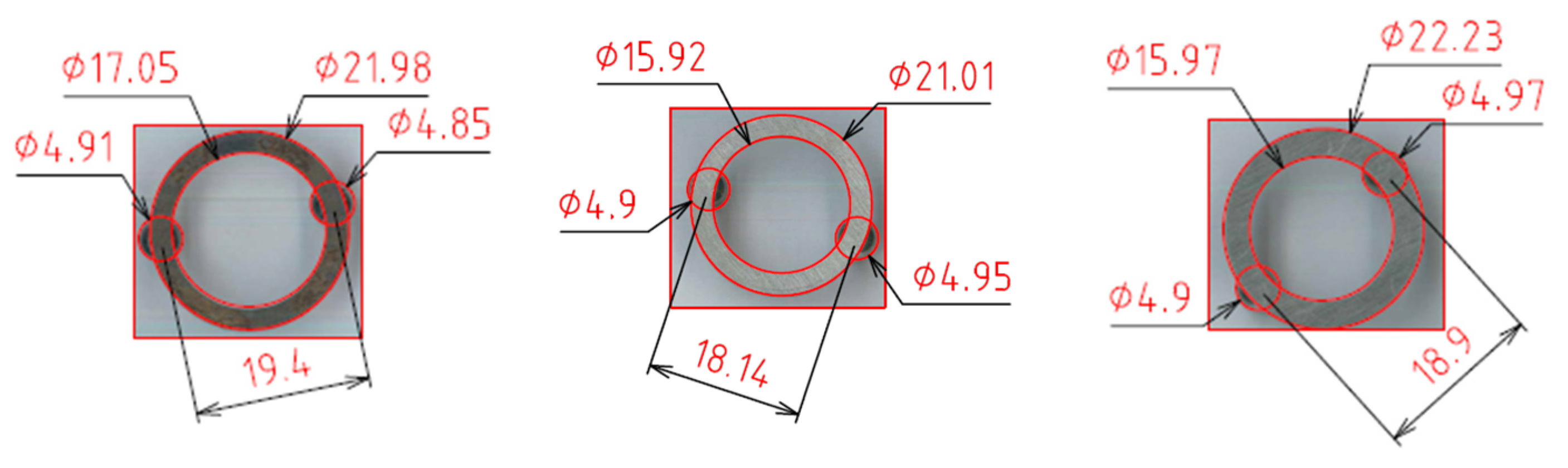
As an illustrative example, when the inner radius rmi is 8.5 mm (diameter ϕ17 mm) and the outer radius rmo is 11 mm (diameter ϕ22 mm), the theoretical magnetic resistance equilibrium position is determined to be r = 9.67 mm (diameter ϕ19.34 mm). This equilibrium position exhibits a slight inward shift relative to the geometric midpoint (r = 9.75 mm, diameter ϕ19.5 mm). The experimental verification is presented in Figure 8, where the measured distance between the two magnetic beads is ϕ19.40 mm. Compared to the theoretical prediction of ϕ 19.34 mm, the relative error is approximately 0.3% (|19.40 − 19.34|/19.34). The relative errors for the remaining two experimental configurations were recorded at 0.2% and 0.3%, respectively, demonstrating high consistency between the theoretical model and the empirical measurements.

3.2. Results of the Multi-Objective Optimization

To validate the proposed optimization procedure, the optimized design (OPT: A = 8, B = 10.5, C = 0.5, D = 1.5) was evaluated and compared with the best case from the original Taguchi experiments (Experiment 2). The simulation results under three magnetic bead diameters are summarized in Table 5. The optimized design exhibits consistently lower Y-direction magnetic resistance, while the Z-direction magnetic attraction force is slightly reduced. Notably, the standard deviations of both responses are smaller in the optimized design, indicating improved robustness against geometric variation. The multi-objective evaluation results are presented in Table 6, where the optimized design achieves a higher composite objective value (OBJ = 0.2410) than Experiment 2 (OBJ = 0.2209). These results confirm that the proposed optimization strategy improves both overall performance balance and robustness of the design.
We compared the optimized simplified prototype (using the optimal parameters identified in the Taguchi array, specifically Experiment 2) with the manufacturer’s original design. The empirical results demonstrate significant improvements:
Engagement Stability: The original design suffered from intermittent transmission failures where the output ring would occasionally fail to engage during input cam rotation. The optimized prototype achieves consistent and reliable power transmission.
Disengagement Reliability: In the original design, the magnetic beads would occasionally “jam” the output ring when the input cam stopped. In the optimized version, the beads consistently return to the maximum permeance position, ensuring the output ring is completely decoupled and can be easily rotated by hand without resistance.

4. Discussion

This study proposes a multi-objective optimization framework to balance two conflicting functional requirements in a permanent magnet mechanical clutch: reducing Y-direction magnetic resistance for rapid disengagement and maintaining sufficient Z-direction magnetic attraction force for stable rolling behavior. The results clearly demonstrate that these two responses exhibit a trade-off relationship, confirming the necessity of employing a multi-objective rather than a single-objective optimization strategy.
The statistical analyses consistently indicate that axial distance (factor D) is the most influential parameter affecting the composite performance index, followed by the outer radius (factor B) and inner radius (factor A). This finding is physically reasonable because the axial distance directly governs the magnetic flux distribution between the magnetic bead and the iron washer, thereby simultaneously affecting both magnetic resistance and attraction. Adjusting this distance therefore provides an effective means to balance disengagement capability and rolling stability.
The comparison between the best original experimental case (Experiment 2) and the optimized design further validates the proposed framework. Although the optimized design exhibits a moderate reduction in Z-direction magnetic attraction force (though the force remains at least 50 times greater than the magnetic ball’s own weight), it achieves improved Y-direction resistance performance and, more importantly, reduced standard deviations for both responses. The decrease in variability indicates enhanced robustness against geometric variations caused by changes in magnetic bead diameter. This robustness is particularly important for practical applications, where manufacturing tolerances and assembly deviations are unavoidable.
Additional sensitivity analysis using weighted-sum and geometric-mean formulations was conducted to evaluate the robustness of the proposed multi-objective aggregation strategy. The results indicate that weighted-sum formulations may favor extreme single-response solutions, whereas the multiplicative and geometric-mean formulations consistently favor balanced solutions. Furthermore, the multiplicative and geometric-mean methods produced identical experiment rankings, confirming that the identified optimal solutions are not artifacts of a specific aggregation strategy. Detailed comparison results are provided in Appendix A.
These results confirm that the proposed combination of Taguchi experimental design, S/N-based normalization, and regression-based optimization provides a reliable and practical approach for improving both performance balance and design stability in permanent magnet mechanical clutch systems.

5. Conclusions

This study evaluated a multi-objective optimization approach for a permanent magnet mechanical clutch using magnetostatic Maxwell simulation, Taguchi experimental design, S/N-based normalization, and regression modeling. Within the specific scope and boundary constraints of this numerical analysis, the primary findings are summarized as follows:
  • A composite objective function (OBJ) was constructed to integrate the Y-direction magnetic resistance and Z-direction magnetic attraction force, providing a systematic means to assess the trade-off behavior between disengagement tendencies and the positional retention of the magnetic beads at different positions.
  • Within the evaluated parameter ranges, statistical analysis indicated that the axial distance (factor D) was the dominant design factor influencing the target responses, followed by the outer radius (factor B) and inner radius (factor A), which aligned with the trends observed in the simulated magnetic flux distribution.
  • The identified parameter configuration (A = 8, B = 10.5, C = 0.5, D = 1.5) yielded a higher composite objective value than the discrete trials within the initial orthogonal array, demonstrating the utility of the regression model as a localized screening tool within the tested space.
  • The prototype-based functional testing confirms that the proposed optimization strategy effectively improves engagement stability and disengagement reliability.
These initial findings suggest that the integration of magnetostatic analysis and orthogonal arrays offers an exploratory design guideline for evaluating competing magnetic forces, serving as a preliminary framework for the future development and physical prototyping of permanent magnet mechanical clutch systems.

Author Contributions

Conceptualization, G.H. and C.L.; methodology, G.H. and C.L.; validation, G.H. and C.L.; formal analysis, G.H., C.L. and B.H.; investigation, B.H.; resources, G.H. and C.L.; data curation, G.H. and C.L.; writing—original draft preparation, G.H. and C.L.; writing—review and editing, G.H. and C.L.; visualization, G.H. and C.L.; supervision, G.H.; project administration, G.H.; funding acquisition, G.H. All authors have read and agreed to the published version of the manuscript.

Funding

This work was supported by the Ministry of Education (MOE) and Bintronic Enterprise Co., Ltd., grant number CSU(112)-187.

Institutional Review Board Statement

Not applicable.

Informed Consent Statement

Not applicable.

Data Availability Statement

The original contributions presented in this study are included in the article. Further inquiries can be directed to the corresponding author.

Acknowledgments

The authors would like to acknowledge the financial support from Binteng Enterprise Co., Ltd. through an industry–academia collaboration project (Technology Transfer), as well as the Ministry of Education for providing the research grant.

Conflicts of Interest

The authors declare that this study received funding from Bintronic Enterprise Co., Ltd. The funder was not involved in study design; the collection, analysis, or interpretation of data; the writing of this article; or the decision to submit it for publication.

Appendix A. Sensitivity Analysis of Multi-Objective Aggregation Methods

To further evaluate the robustness of the proposed multi-objective aggregation strategy, additional sensitivity analysis using weighted-sum and geometric-mean formulations was conducted. The results indicate that weighted-sum formulations may favor extreme single-response solutions, whereas the multiplicative and geometric-mean formulations consistently favor balanced solutions. Furthermore, the multiplicative and geometric-mean methods produced identical experiment rankings, confirming that the identified optimal solutions are not artifacts of a specific aggregation strategy.
Table A1. Comparison of experiment rankings obtained using different aggregation methods.
EXPMultiplication
Rank
Weighted Sum (0.5/0.5) RankWeighted Sum (0.7/0.3) RankGeometric Mean Rank
14174
21641
36936
45525
58398
63863
72752
88318
97287

References

  1. Wang, Q.; Gao, F.; Zhang, J.; Li, Y. Analysis and reduction of detent effect in magnetic lead screws with parallel magnetized permanent magnet segments. IEEE Access 2020, 8, 84177–84187. [Google Scholar] [CrossRef]
  2. Belguerras, L.; Hadjout, L.; Mezani, S.; Lubin, T.; Rezzoug, A. Study of HTS magnetic coupler using analytical and numerical computations. IEEE Trans. Appl. Supercond. 2014, 24, 3600912. [Google Scholar] [CrossRef]
  3. Wang, J.; Hou, X. Small Clutch, and Motor and Electric Curtain Using Same. Chinese Patent No. CN101871493A, 27 October 2010. Available online: https://patents.google.com/patent/CN101871493A/zh?oq=CN101871493A (accessed on 19 May 2026).
  4. Cai, W.; Gu, C.; Hu, X. Analysis and design of a permanent magnet bi-stable electro-magnetic clutch unit for in-wheel electric vehicle drives. Energies 2015, 8, 5598–5612. [Google Scholar] [CrossRef]
  5. Andriushchenko, E.; Kaska, J.; Kallaste, A.; Belahcen, A.; Vaimann, T.; Rassõlkin, A. Design optimization of permanent magnet clutch with Ārtap framework. Period. Polytech. Electr. Eng. Comput. Sci. 2021, 65, 106–112. [Google Scholar] [CrossRef]
  6. Diao, Z.; Zhang, Y.; Li, C.; Liu, X.; Liu, Z. Dynamic characteristics of an automotive air-conditioning electromagnetic clutch. Processes 2023, 12, 80. [Google Scholar] [CrossRef]
  7. Kob, M.S.C.; Supriyo, B.; Tawi, K.B.; Mazali, I. Engagement slip controller development based on actuator displacement for an electro-mechanical friction clutch system. Int. J. Automot. Mech. Eng. 2015, 11, 2664–2674. [Google Scholar] [CrossRef]
  8. Molina, L.C.; Galluzzi, R.; Hegde, S.; Bonfitto, A.; Amati, N.; Tonoli, A.; Ventura, W. Active electromagnetic clutch for crankshaft decoupling from a belt drive system. Appl. Sci. 2024, 14, 4770. [Google Scholar] [CrossRef]
  9. Rizzo, R.; Musolino, A.; Bucchi, F.; Forte, P.; Frendo, F. A multi-gap magnetorheological clutch with permanent magnet. Smart Mater. Struct. 2015, 24, 075012. [Google Scholar] [CrossRef]
  10. Simonelli, C.; Sani, L.; Gori, N.; Fernández-Muñoz, M.; Musolino, A.; Rizzo, R. Experimental validation of a permanent magnets magnetorheological device under a standardized worldwide harmonized light-duty test cycle. Actuators 2023, 12, 375. [Google Scholar] [CrossRef]
  11. Peng, Z.; Zheng, Z.; Yang, S.; Zhao, X.; Yu, X.; Han, D. Design and optimization of a pneumatic micro valve with symmetric magnetic yoke and permanent magnet assistance. Actuators 2025, 14, 388. [Google Scholar] [CrossRef]
  12. Pisetskiy, S.; Kermani, M. High-performance magneto-rheological clutches for direct-drive actuation: Design and development. J. Intell. Mater. Syst. Struct. 2021, 32, 2582–2600. [Google Scholar] [CrossRef] [PubMed]
  13. Chowdhary, A.; Kumar, A.; Singh, K.S. Design and analysis of an electro-magnetic clutch. Int. J. Progress. Res. Sci. Eng. 2020, 1, 89–95. Available online: https://journal.ijprse.com/index.php/ijprse/article/view/57 (accessed on 19 May 2026).
  14. Wu, J.; Liu, Y.; Xie, H. Experimental measurement of a multi-pole magnetorheological fluid clutch under air cooling. Rev. Sci. Instrum. 2024, 95, 035003. [Google Scholar] [CrossRef] [PubMed]
  15. Tucci, M.; Sani, L.; Dio, V.D. Optimization of a novel magneto-rheological device with permanent magnets. Prog. Electromagn. Res. M 2017, 62, 175–188. [Google Scholar] [CrossRef]
  16. Tweedy, O.R.; Akcay, Y.; Giangrande, P.; Galea, M. Concept and demonstration of a coaxial magnetic coupling with electromagnetic disconnection for aircraft permanent magnet generators. IEEE Trans. Transp. Electrif. 2023, 9, 4094–4103. [Google Scholar] [CrossRef]
  17. Jackel, M.; Kloepfer, J.; Matthias, M.; Seipel, B. The novel MRF-ball-clutch design—A MRF-safety-clutch for high torque applications. J. Phys. Conf. Ser. 2013, 412, 012051. [Google Scholar] [CrossRef]
  18. Kluszczynski, K.; Pilch, Z. A comparison study on magnetorheological multi-disc clutches in steady continuous-duty states from the viewpoint of electrical energy consumption and spatial temperature distribution. Appl. Sci. 2022, 12, 7895. [Google Scholar] [CrossRef]
  19. Nicholson, S. Clutch Mechanism for Manual Roller Door Operation. U.S. Patent No. 6029735A, 17 December 1998. [Google Scholar]
  20. Qiu, Y. Curtain Operation Controller with Built-In Clutch. Chinese Patent No. CN102755096A, 31 July 2012. [Google Scholar]
  21. Tsai, J. Mechanical Clutch of Motor for Opening and Closing Curtain. Chinese Patent No. CN202991928U, 10 January 2013. [Google Scholar]
  22. Kao, L. Built-In Clutch and Combined Motor with Same. Chinese Patent No. CN103206468A, 31 July 2013. [Google Scholar]
  23. Wang, J. Small-Sized Clutch, Electric Motor Having Small-Sized Clutch and Electro-Motion Curtain Having Small-Sized Clutch. Chinese Patent No. WO2011150819A1, 31 May 2011. [Google Scholar]
  24. Luo, Y. Clutch for Intelligent Window. Chinese Patent No. CN210799816U, 18 September 2019. [Google Scholar]
  25. Tang, R.; Liu, S.; Wu, X. Clutch Failure Prevention Structure and Method for Clutch. Chinese Patent No. CN112983999A, 13 April 2021. [Google Scholar]
  26. Andriushchenko, E.; Kallaste, A.; Belahcen, A.; Vaimann, T.; Rassõlkin, A.; Heidari, H.; Tiismus, H. Optimization of a 3D-printed permanent magnet coupling using genetic algorithm and taguchi method. Electronics 2021, 10, 494. [Google Scholar] [CrossRef]
  27. Mrak, B.; Lenaerts, B.; Driesen, W.; Desmet, W. Optimal design of magnetic springs: Enabling high life cycle elastic actuators. In Proceedings of the 15th International Symposium on Magnetic Bearings (ISMB16), Kitakyushu, Japan, 3–6 August 2016. [Google Scholar]
  28. Luo, W.; Li, Y.; Jiang, H.; Zheng, Y.; Cheng, X.; Liu, W. An optimal design approach for permanent magnet coupling using multiple shallow neural networks. SSRN 2025. Available online: https://papers.ssrn.com/sol3/papers.cfm?abstract_id=5555074 (accessed on 19 May 2026).
  29. Ravaud, R.; Lemarquand, V.; Lemarquand, G. Analytical design of permanent magnet radial couplings. IEEE Trans. Magn. 2010, 46, 3860–3865. [Google Scholar] [CrossRef]
  30. Roters, H.C. Calculation of the permeance of flux paths through air between surfaces of high-permeability material. In Electromagnetic Devices, 1st ed.; John Wiley & Sons: Hoboken, NJ, USA, 1941; pp. 116–121. [Google Scholar]
Figure 1. The 3D CAD model of the PM mechanical clutch.
Applsci 16 05363 g001
Figure 2. The prototype of the PM mechanical clutch.
Applsci 16 05363 g002
Figure 3. Static Magnetic Circuit Model of Permanent Magnet Clutch.
Applsci 16 05363 g003
Figure 4. Schematic diagram of a simplified model of radial magnetic permeability. The parameter symbols in Figure 4 are explained as follows: d: Vertical distance between magnetic sphere and iron washer. t: Thickness of iron washer. rmi: Inner radius of iron washer. rm: Radius position of minimum magnetic energy. rmo: Outer radius of iron washer. dr: Radial infinitesimal change.
Applsci 16 05363 g004
Figure 5. B-H Curve of Steel_1008.
Applsci 16 05363 g005
Figure 6. Magnetic Flux Density Distribution. (a) Bead position at IR. (b) Bead position at r m i · r m o . (c) Bead position at r = 12.5 mm.
Applsci 16 05363 g006
Figure 7. Main effects plot of factors for the composite objective function (OBJ) with respect to washer (A) inner radii, (B) outer radii, (C) thickness, and (D) axial distance.
Applsci 16 05363 g007
Figure 8. Measured dimensions of the magnetic beads at their equilibrium positions (dimensions unit: mm).
Applsci 16 05363 g008
Table 1. Object Specifications, Materials, and Dimensions (dimension unit: mm).
ObjectMaterialDimension (mm)Mesh (mm)
Magnetic beadBuilt-in NdFe35ϕ4.8~5.21
Iron washerBuilt-in Steel_1008IR: ϕ8~9, OR: 10.5~11.5, t: 0.5~1.50.5
0.5
Air GapBuilt-in Airϕ10 × 81
RegionBuilt-in VacuumPad all directions similarly, Percentage Offset: 100
Table 2. Taguchi L9 experimental design and simulation results for Y-direction magnetic resistance and Z-direction magnetic force. (dimension unit: mm, force unit: N).
ABCDY-Direction Magnetic
Resistance at OR
Z-Direction Magnetic
Force at OR
EXPIR
rmi
OR
rmo
Thickness
t
Distance
d
Y1
(ϕ4.8)
Y2
(ϕ5.0)
Y3
(ϕ5.2)
Z1
(ϕ4.8)
Z2
(ϕ5.0)
Z3
(ϕ5.2)
1810.50.510.1750.1880.2020.5990.6590.717
281111.50.1180.1360.1560.3840.4440.51
3811.51.520.0750.0880.1040.2390.2780.322
48.510.5120.0680.080.0920.2380.2770.32
58.5111.510.2020.230.2610.6610.7520.861
68.511.50.51.50.1330.1290.1460.3750.4280.483
7910.51.51.50.1180.1360.1570.3840.4440.51
89110.520.0610.0650.0730.2180.2440.27
9911.5110.1980.2260.2560.6580.7480.843
Table 3. Multi-objective evaluation results based on normalized S/N ratios.
Y-Direction Magnetic Resistance
(Smaller-the-Better)
Z-Direction Magnetic Force
(Larger-the-Better)
OBJ
EXPY_AVGY_SY_SNRYnZ_AVGZ_SZ_SNRZnYnxZn
10.18830.011014.48660.16630.65830.0482−3.70140.88320.1469
20.13670.015517.23110.41900.44600.0515−7.18750.52730.2209
30.08900.011920.93580.76010.27970.033911.25920.11150.0848
40.08000.009821.87350.84650.27830.033511.29830.10750.0910
50.23100.024112.68080.00000.75800.0818−2.55761.00000.0000
60.13600.007317.31690.42690.42870.0441−7.49650.49570.2116
70.13700.015917.20720.41680.44600.0515−7.18750.52730.2198
80.06630.005023.54091.00000.24400.021212.35160.00000.0000
90.22670.023712.84510.01510.74970.0755−2.63570.99200.0150
Table 4. ANOVA results for the composite objective function (OBJ).
SourceDOFSSMSFp
A20.0082820.00414116.940.056
B20.0095190.00475919.470.049
D20.0519710.025985106.280.009
Error20.0004890.000245
Total80.070260
Table 5. Comparison of Y-direction magnetic resistance and Z-direction magnetic force between Experiment 2 and optimized design.
ABCDY-Direction Magnetic
Resistance
Z-Direction Magnetic
Force
EXPIR
rmi
OR
rmo
Thickness
t
Distance
d
Y1
(ϕ4.8)
Y2
(ϕ5.0)
Y3
(ϕ5.2)
Z1
(ϕ4.8)
Z2
(ϕ5.0)
Z3
(ϕ5.2)
281111.50.1180.1360.1560.3840.4440.51
OPT810.50.51.50.1090.1180.1310.3660.4040.450
Table 6. Comparison of multi-objective evaluation results between Experiment 2 and the optimized design.
Y-Direction Magnetic Resistance
(Smaller-the-Better)
Z-Direction Magnetic Force
(Larger-the-Better)
OBJ
EXPY_AVGY_SY_SNRYnZ_AVGZ_SZ_SNRZnYnxZn
20.13670.015517.23110.41900.44600.0515−7.18750.52730.2209
OPT0.11920.009218.44620.53090.40670.0341−7.90510.4540.24102
Disclaimer/Publisher’s Note: The statements, opinions and data contained in all publications are solely those of the individual author(s) and contributor(s) and not of MDPI and/or the editor(s). MDPI and/or the editor(s) disclaim responsibility for any injury to people or property resulting from any ideas, methods, instructions or products referred to in the content.