1. Introduction
Speed elevator technology has undergone rapid iterations. Consequently, public demands for operational safety, robustness, high efficiency, energy conservation, and ride comfort continue to escalate [
1]. Compared with traditional models, high-speed elevators possess significant advantages in travel distance and velocity; however, this also renders their traction systems more susceptible to multi-source excitations. The dynamic vibration phenomena induced during operation have become critical factors constraining equipment service safety and ride quality [
2].
During the operation of elevator systems, traction machine excitation serves as one of the primary causes of vertical vibration [
3]. As the power core of the elevator, the operational characteristics of the traction machine directly dictate the vibration state of the entire system. When the traction machine starts or brakes, abrupt changes in motor torque generate impact loads within the system, inducing transient vibrations [
4]. Simultaneously, during continuous operation, the traction machine generates periodic excitation forces due to factors such as rotor eccentricity, bearing clearance, and gear meshing [
5]. These excitation forces are transmitted through the traction sheave to the steel wire ropes, subsequently acting upon the car system. Particularly when the excitation frequency approaches the natural frequency of the system, resonance phenomena are easily triggered, leading to a significant amplification in vibration amplitude.
For high-speed elevators, as the travel velocity increases, various excitation frequencies escalate accordingly, exacerbating vibration issues. A higher concentration of system vibration frequencies increases the susceptibility to resonance. Furthermore, higher operational velocities induce stronger impacts and correspondingly larger vibration responses, thereby degrading the safety and comfort of the high-speed elevator [
6]. To investigate the vibration conditions of high-speed elevators, it is imperative to establish an accurate and reliable dynamic model, calculate the system’s natural frequencies [
7] and dynamic responses, and explore the dynamic behaviors under diverse excitations. This approach is essential for grasping the vibration characteristics of high-speed elevators and formulating effective vibration control schemes.
To address the dynamic modeling and vibration issues of high-speed elevators in the longitudinal direction, scholars have conducted extensive research.
Regarding modeling depth, Tian et al. [
8] proposed an integrated modeling approach comprising eight subsystems that decouple linear and nonlinear components, establishing a time-varying nonlinear dynamic model for hoisting ropes. By employing a variable step-size fourth-order Runge–Kutta method, high-precision time-domain solutions were achieved. Furthermore, this work systematically revealed the influence of laws of car position, control strategies, and load variations on the longitudinal vibration of high-speed elevators. Hu et al. [
9] focused on the vibration control of high-speed elevators, proposing a roller guide shoe structure based on a hydraulic damping actuator. Through a mechanical-electrical-hydraulic co-simulation model, they demonstrated that this method could significantly attenuate car vibration under various excitation conditions. Jiang et al. [
10] studied vibrations induced by aerodynamic disturbances in ultra-high-speed elevators, establishing a fluid-solid coupling dynamic model and combining multi-objective optimization with an LQR control strategy to achieve vibration suppression. Zhang et al. [
11] addressed vibration control in ultra-high-speed elevators by proposing an intelligent control method based on a type-2 fuzzy neural network, which effectively manages complex nonlinear vibration systems while accounting for input saturation effects. Song [
12] established four external excitation models—sine, triangular, step, and impulse excitations—and analyzed the factors influencing the vibration response by solving the coupled system’s vibration acceleration.
In related studies, Zhang et al. [
13] formulated the elevator dynamic equations under a 1:1 roping ratio, defined the rotational imbalance of the traction sheave as a vertical excitation source, and obtained the displacement and acceleration responses under forced conditions. Yu et al. [
14] focused on dynamic loads during the acceleration and deceleration phases, abstracting the inertial forces generated during starting and braking as external excitations to qualitatively analyze their impact on operational stability. Liu [
15] comprehensively considered the superimposed effects of eccentric imbalance and inertial loads within a 7-degree-of-freedom model. Liang et al. [
16] established an 8-degree-of-freedom vertical dynamic model for a 2:1 traction elevator, investigating the impacts of inertial forces during starting and braking, as well as the eccentric imbalance of the car roof return sheave. Guo et al. [
17] investigated a variable-length flexible hoisting structure similar to elevator systems. Based on Hamilton’s principle, they established a longitudinal-transverse-lateral coupled nonlinear dynamic model and utilized the Galerkin method for discrete solution, emphasizing the effects of operational acceleration, jerk, and motion trajectory on system vibration characteristics.
Although existing research has made considerable progress in the vibration modeling and control of high-speed elevators, most studies focus primarily on dynamic response analysis and control strategy design, with limited systematic coupling research from the perspectives of structural design optimization and failure mechanisms. In recent years, multi-stage topology optimization methods for complex engineering structures have been widely applied in the rail transit sector. Cascino et al. [
18] implemented a multi-stage optimization strategy combining global and local approaches in the structural redesign of railway locomotive bogie frames. This achieved a rational reconstruction of the structural mass distribution, significantly reducing mass and optimizing vibration characteristics while ensuring stiffness and dynamic performance. This method provides an important reference for the structural optimization of elevator car frames and key components of the traction system. Meanwhile, lightweight material design has become a crucial means of reducing structural inertia and vibration responses. Juan et al. [
19] utilized Glass Fiber Reinforced Polymer (GFRP) pultruded composites to replace traditional metal structures, significantly reducing system mass and inertia while maintaining high structural stiffness, thereby effectively improving dynamic response characteristics. Introducing such lightweight design concepts to elevator car frames and auxiliary components is expected to reduce the dynamic loads acting on the hoisting rope system and mitigate vibration and stress concentration issues. Furthermore, for critical load-bearing components such as hoisting ropes, relying solely on stress amplitude analysis is insufficient for a comprehensive evaluation of service safety. The dynamic stress analysis and fatigue evaluation methods for open-type mechanical structures discussed by Peterson et al. [
20] provide a more rigorous theoretical basis for identifying local stress concentrations and potential fatigue damage. Nencioni et al. [
21] established multibody dynamics models integrated with multi-source sensor data for railway freight wagon systems, enabling real-time prediction and experimental validation of structural dynamic responses. This approach provides a reliable basis for condition monitoring and fault diagnosis, offering valuable insights for the dynamic behavior analysis of elevator systems subjected to multi-source external excitations.
This paper establishes a precise multi-degree-of-freedom dynamic model for the vertical vibration of high-speed elevators based on the substructure method. The system is discretized into distinct subsystems, including the traction, tensioning, car and car frame, counterweight, and steel wire ropes. The governing dynamic equations are derived utilizing Lagrange’s equations and Newton’s second law, and are thoroughly validated through both the Jacobi threshold method and ADAMS simulations. The study emphatically analyzes the effects of traction sheave eccentric excitation, reverse braking torque excitation, and guide rail joint impact excitation on the car’s longitudinal vibration and the dynamic stress variations in the steel wire rope. Ultimately, this paper provides theoretical support for vibration reduction and ride comfort optimization in high-speed elevators.
2. High-Speed Elevator Dynamics Model
The vertical vibration characteristics of high-speed elevator systems are governed by several critical assemblies, including the traction system, suspension ropes, car-frame structure, counterweight, tensioning device, and speed governor. The principal elastic elements integrated within the system consist of dual-layer vibration isolation rubber in the traction machine assembly, damping rubber at the car floor, and rope-end springs at the termination of the car-side and counterweight-side wire ropes. Integrating these factors, a substructure-based approach is adopted to model the dynamic response of each vibrational component. For the purposes of modeling and numerical solution, it is assumed that the vertical and horizontal vibrations within the high-speed elevator system are decoupled. Accordingly, the stiffness parameters defined for the following components refer exclusively to the vertical degrees of freedom.
2.1. Traction Subsystem Model
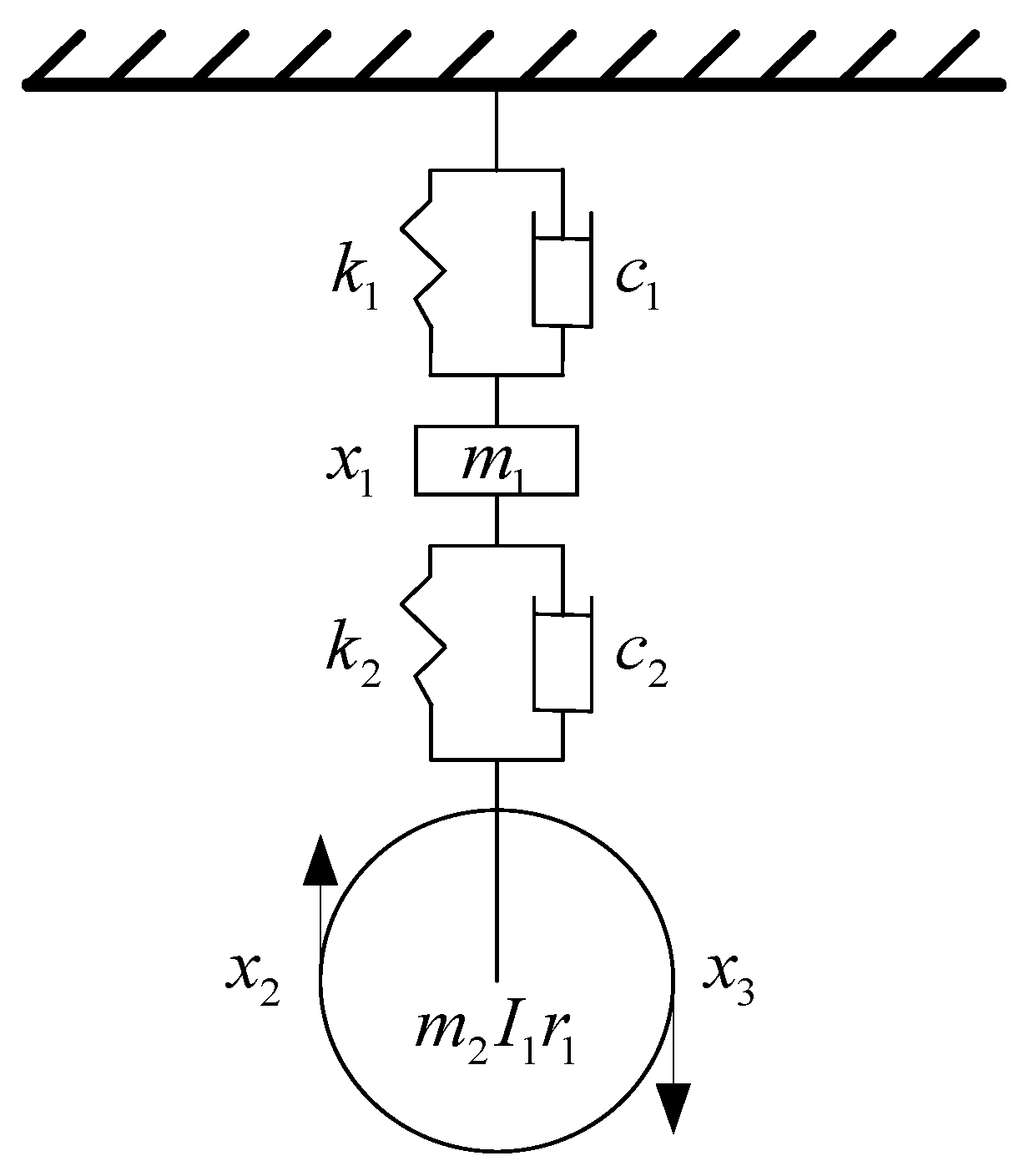
The traction subsystem in elevators exhibits high complexity, necessitating the application of Lagrange’s equations to formulate its dynamics. As illustrated in
Figure 1, the vibration isolation rubber within the traction assembly is modeled as a spring-damping system. This configuration is represented as a three-degree-of-freedom (3-DOF) lumped-mass model.
Where are the three degrees of freedom of the traction subsystem. is the centralized mass displacement of the tractor, is the displacement of the contact point of the traction sheave with the rope on the car side, is the displacement of the contact point of the traction sheave with the rope on the counterweight side, and is specified in a generalized coordinate system, with the car moving upwards in the positive direction.
The kinetic energy, elastic potential energy, and dissipative energy of the traction subsystem can be expressed as follows:
Substituting the aforementioned expressions into Lagrange’s equations yields:
The differential equations governing the dynamics of the traction subsystem are formulated as follows:
The contribution quality matrix for the subsystem is as follows:
The contribution stiffness matrix is:
The contribution damping matrix is:
In the aforementioned equations, represents the combined mass of the motor and the traction sheave bedplate, while denotes the equivalent mass of the traction and deflector sheave assembly. The parameters and ( = 1, 2) correspond to the vertical stiffness and damping coefficients of the isolation mounts. Additionally, is defined as the equivalent rotational inertia of the traction sheave with a radius of .
2.2. Tensioning System Model
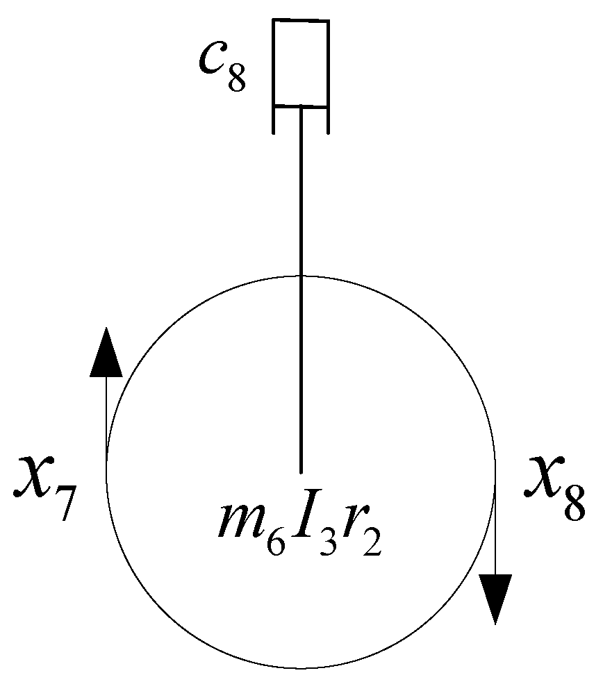
The tensioning subsystem functions similarly to the traction subsystem. Unlike the traction sheave, the tensioning sheave lacks vibration-isolating rubber, with damping assumed to be zero.
Figure 2 depicts the tensioning subsystem.
Where and are the displacements of the wire rope on the right and left sides of the tension pulley, respectively.
The same Lagrange equation can be used to obtain the contributing mass matrix
, the contributing stiffness matrix
, and the contributing damping matrix
of the tension subsystem.
2.3. Elevator Car Frame Model
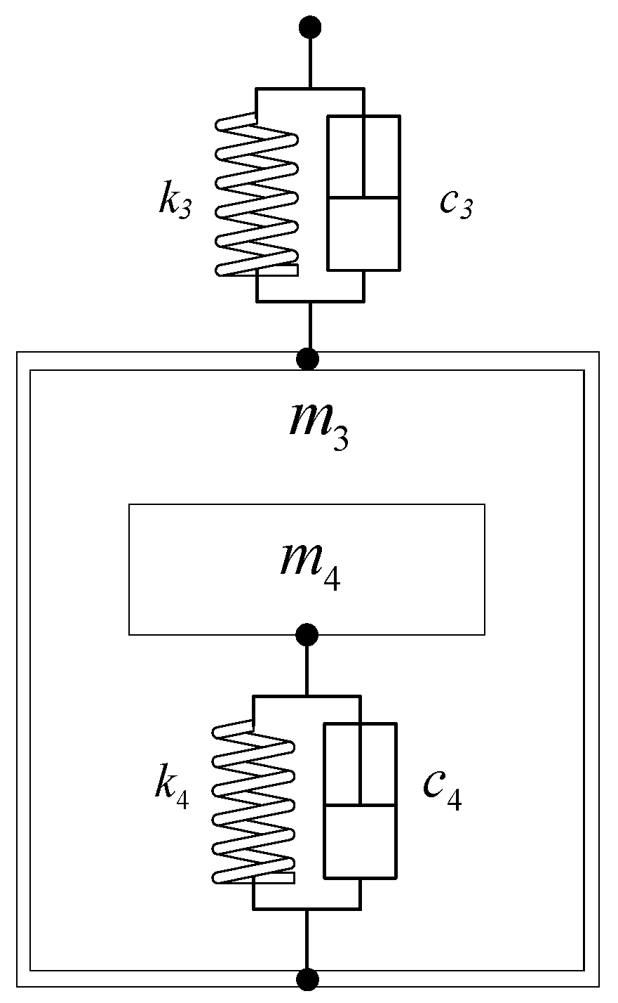
The car-frame, cabin, and counterweight subsystems are modeled as linear substructures with specified DOFs using Newton’s second law. The dynamic analysis focuses exclusively on vertical vibrations, accounting for the isolation rubbers at the car bottom while omitting the lateral components, as illustrated in
Figure 3.
Where
and
denote the masses of the car-frame and the cabin, respectively;
and
represent the stiffness and damping coefficients of the rope-end springs;
and
signify the stiffness and damping parameters of the vibration isolation rubber at the car bottom. Applying Newton’s second law, the governing differential equations for the car-frame and cabin subsystems are formulated as follows:
Solve the contributing mass matrix of the car and frame subsystem as:
The contributing stiffness matrix is:
The contribution damping matrix is:
The counterweight subsystem mirrors the car and frame subsystem. It involves selecting the connection point of the rope head spring on the counterweight with the traction rope, along with the counterweight displacement, as degrees of freedom to construct the model. Newton’s second law is utilized to obtain the contributing mass matrix , contributing stiffness matrix , and contributing damping matrix of the counterweight subsystem.
2.4. Discrete Segmented Rope Model
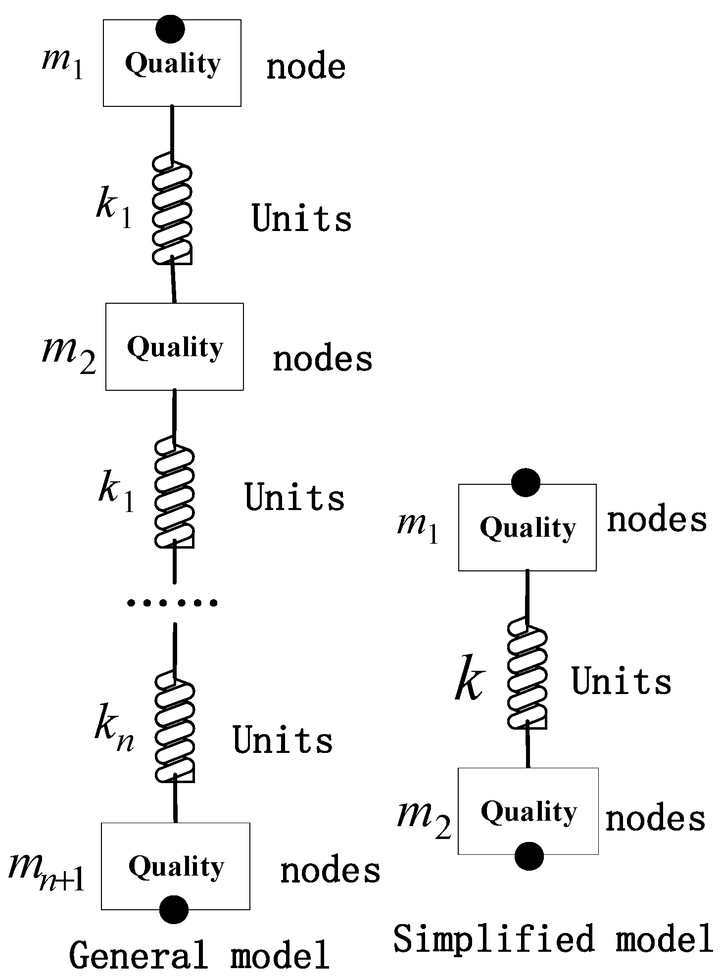
The discretized model of the wire ropes is illustrated in
Figure 4. To ensure high computational fidelity, both the traction and compensation ropes are modeled as discrete mass-spring-damper assemblies. Specifically, the continuous ropes are partitioned into n segments, consisting of n + 1 lumped masses connected by n massless springs with uniform elastic coefficients. In this configuration, mi and kn denote the mass and stiffness of each discrete element, respectively.
To ensure the validity of the wire rope discretization resolution, a convergence analysis of the system’s dynamic characteristics was performed for different numbers of segments
.
Table 1 illustrates the variation in frequencies as
increases.
As illustrated in
Table 1, the dominant natural frequencies of the system tend to stabilize when
> 5. Given that the fundamental frequency of the external excitations investigated in this study is approximately 4 Hz, the first three modes captured by the discrete model adequately encompass the response intervals of the fundamental frequency and its second harmonic. Regarding computational efficiency, further increasing the number of segments yields a negligible marginal contribution to the prediction accuracy of low-frequency vibrations. Furthermore, the car frame system exhibits pronounced low-pass filtering characteristics, effectively attenuating subtle higher-frequency modes. Consequently, selecting
= 5 achieves the optimal balance between computational efficiency and model fidelity.
2.5. Speed Limiter System Model
To comprehensively describe the multi-degree-of-freedom (MDOF) system, the global independent generalized displacement vector
of the system is first defined. Assuming that the traction wire rope and the compensation wire rope are discretized into n segments, respectively, the global state vector
X is defined as:
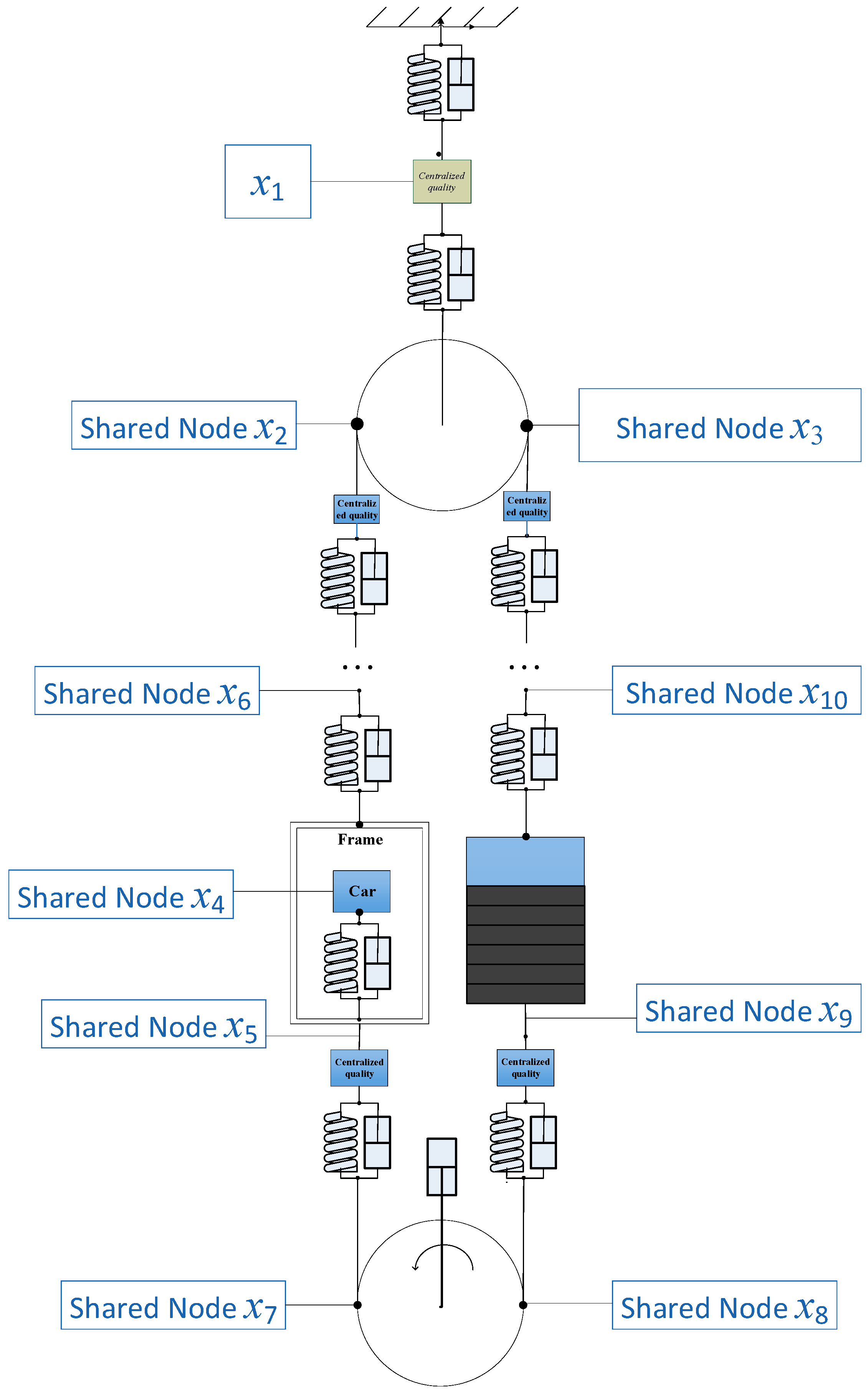
In the established dynamic model, the physical meanings of the system’s degrees of freedom are defined as follows: , and denote the displacement of the traction machine lumped mass and the displacements of the contact points between the traction sheave and the traction ropes on the car side and counterweight side, respectively; , and represent the displacements of the elevator car, the car frame, and the car frame suspension point (the connection point between the wire rope and the rope hitch spring), respectively; and correspond to the displacements of the contact points between the tensioning sheave and the tensioning ropes on the car and counterweight sides; and signify the displacements of the counterweight and its corresponding suspension point (the connection point between the wire rope and the rope hitch spring). Additionally, and refer to the displacement vectors of the traction wire ropes, while and correspond to the displacements of the compensation wire ropes.
The substructures are coupled via shared degree-of-freedom (DOF) nodes, which serve as the interfaces between the components. This assembly approach strictly adheres to the principle of displacement continuity, ensuring that physical quantities—such as displacement and velocity—remain consistent at the connection points within the mathematical description. The resulting dynamic model of the elevator system is illustrated in
Figure 5.
Based on finite element theory, the global mass, stiffness, and damping matrices (
,
, and
) of the assembled system are obtained by assembling the respective matrices of each individual substructure.
By utilizing the substructure method, the contribution matrices of the traction subsystem, tensioning subsystem, car and car frame subsystem, counterweight subsystem, and wire rope models are assembled to yield the global mass matrix
M, stiffness matrix
K, and damping matrix
C of the entire elevator system. The resulting integrated dynamic model is illustrated in
Figure 5. The governing equations of motion for the system can be formulated as:
where x denotes the generalized displacement vector, and
represents the external excitation vector. Specifically,
encompasses the centrifugal force
induced by the traction sheave eccentricity, as well as the equivalent force
converted from the reverse braking torque during the braking process. For the convenience of subsequent calculations, it is necessary to list the basic parameters of the elevator, as shown in
Table 2.
2.6. Model Validation
To ensure the accuracy of the established dynamic model and the numerical solver, comprehensive validation is indispensable. The analysis of natural frequencies serves as an effective approach to verify the validity of both the theoretical framework and the computational algorithm.
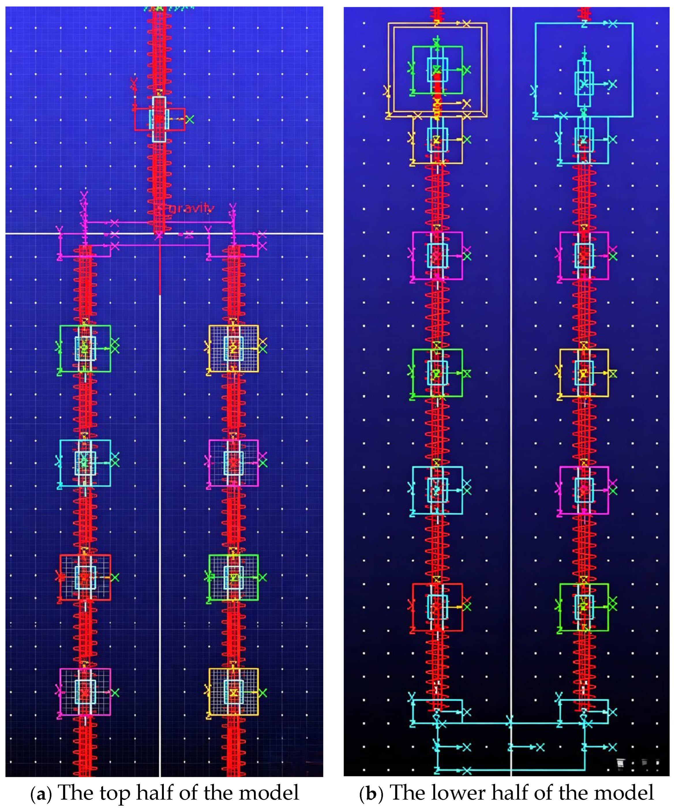
The simulation phase primarily serves to validate the natural frequencies of the system obtained from the previous numerical solutions, during which the effects of damping and external excitations are neglected. In the ADAMS/View environment, parametric modeling of various elevator modules is conducted, where structural components and wire ropes are simplified into equivalent mass-spring-damper models. Translational joints are employed to constrain the car and counterweight, restricting their motion solely to the vertical Z-axis. Revolute joints are utilized to connect the traction and tensioning sheaves, which are simplified as mass elements capable only of axial rotation. Since this validation is focused on natural frequencies, the wire rope segments are further simplified into spring-mass systems. As the determination of natural frequencies falls within the scope of linearized analysis, a static analysis must be performed prior to the frequency analysis to account for the pre-stretching effects of the system under gravity, ensuring that the modal analysis is conducted at the static equilibrium position. Subsequently, a linear modal solver is selected in the simulation control interface to compute the natural frequencies of the substructures. The global model is illustrated in
Figure 6.
In this study, validation is conducted by integrating ADAMS multibody dynamics software with the Jacobi crossing method (JCM). By introducing a “crossing criterion” into the traditional iterative framework, the JCM significantly accelerates the convergence rate. Furthermore, it effectively mitigates issues such as sluggish convergence or divergence typically caused by the suboptimal selection of relaxation factors in the standard Jacobi iteration method.
The Threshold Jacobi Method is recognized as an effective enhancement of the classical algorithm, primarily due to the acceleration achieved in the following two dimensions:
Significant reduction in time complexity: It eliminates the O(N2) comparison overhead required by the classical Jacobi method to search for the maximum off-diagonal element in each iteration.
Targeted allocation of computational resources: By implementing “threshold criteria,” the algorithm prioritizes the elimination of dominant off-diagonal elements (those with larger absolute values) during early iterations while bypassing negligible ones. Only as the overall magnitude of the off-diagonal elements diminishes does the algorithm address finer details. This strategy substantially reduces redundant trigonometric computations and matrix multiplication operations.
A comparative analysis of the system’s natural frequencies before and after the improvements is presented in
Table 3.
As indicated in
Table 3 significant discrepancies exist between the calculated results. A quantitative error analysis based on the ADAMS simulation results reveals that the traditional Jacobi iteration method exhibits substantial accuracy deficiencies, with a maximum relative error of 72.77% and a mean error of 59.07%, which fail to meet engineering requirements. In contrast, the precision of the improved Jacobi cross-method is significantly enhanced, with the maximum relative error reduced to 9.44% and the mean error to 4.93%. These results are consistently within the 10% engineering tolerance, and the errors for low-order modes are generally below 5%. The overall accuracy is improved by more than 12 times compared to the traditional method, validating its reliability for calculating the natural frequencies of high-speed elevators.
It should be noted that the current validation focuses primarily on the system’s natural frequencies. This approach is adopted because the primary objective of this study is to establish a robust MDOF substructure modeling methodology. Accurate prediction of natural frequencies ensures that the model correctly captures the intrinsic mass and stiffness distributions, which are the fundamental determinants of dynamic behavior. While forced vibration responses, such as acceleration time-histories and peak amplitudes, provide practical insights into ride quality, they are highly dependent on specific operational excitations (e.g., stochastic rail irregularities and load variations) that vary between individual installations. To maintain the focus on the proposed modeling framework, these application-specific analyses are considered beyond the current scope. Future research will incorporate high-fidelity excitation data to further evaluate the model’s predictive performance in specific engineering scenarios.
While physical experimentation serves as the definitive validation method, its implementation in high-speed elevator research is often constrained by stringent operational safety protocols and the prohibitive costs of full-scale testing. In the field of mechanical engineering, cross-verification between analytical and numerical models is a widely accepted and effective approach for evaluating dynamic characteristics when field measurements are impractical or hazardous. Future research will seek to integrate empirical data obtained from field tests within controlled environments.
3. Calculation of Forced Vibrations in Elevator Systems
The vibration characteristics of elevator systems are significantly influenced by external excitations. This paper primarily investigates the effects of traction sheave eccentricity, vertical impact excitations from guide rail joints, and variations in reverse braking torque during the deceleration phase on these vibrational properties. These factors act synergistically upon the elevator system, dictating its overall dynamic performance. Considering the specific research object and operating conditions of this study, the mathematical models for these typical external excitations manifest in distinct forms, which are analyzed in detail below.
3.1. Eccentric Excitation Model of the Traction Sheave
In elevator systems, the traction sheave plays a pivotal role in driving the movement of the car and the counterweight. When eccentricity exists within the traction sheave, its rotation generates periodically varying centrifugal forces that influence the operation of the elevator car. This centrifugal force effectively constitutes the eccentric excitation imposed on the elevator system.
To further explore the effect of traction sheave eccentric excitation on elevator ride quality, this paper adopts a traction sheave with an eccentricity of = 3 mm as the typical excitation source. Let denote the centrifugal force generated by the eccentric rotation of the traction sheave, where the elevator operates at a speed of = 6 m/s, the traction sheave has a circumferential radius of = 0.3 m, and the angular velocity is defined as . When only the vertical component is taken into account, the displacement expression of the induced eccentric motion is given by .
The external forces acting on the traction system are:
3.2. Reverse Torque Excitation
During the deceleration-to-stop phase, the reverse braking torque exerted by the motor is not a constant value; instead, it follows a characteristic piecewise profile consisting of a “rise, steady-state, and decay to zero” sequence, which can generally be approximated by the following three stages:
where
denotes the braking torque decay coefficient, with a larger value indicating a slower rate of torque decay;
represents the reverse braking torque; and
is the maximum value of the reverse braking torque.
It should be noted that the decay coefficient of the torque characteristic is intrinsically linked to the tribological properties of the brake linings. Typically, the dynamic friction coefficient is not a constant, as it is highly sensitive to the interface temperature and sliding velocity. Generally, the decay coefficient exhibits a negative correlation with the tribological performance of the linings. During high-speed emergency braking, instantaneous thermal accumulation can lead to thermal fading, which may diminish braking effectiveness in the final stages of deceleration and result in prolonged braking durations. Furthermore, the wear status of the friction pair introduces structural nonlinearities. Long-term wear increases the air gap between the brake shoe and the disk, which may manifest as a time delay in torque application and an amplification of the initial jerk. While incorporating all these multi-physics factors would significantly increase the computational complexity, for the purpose of model simplification and focusing on the primary dynamic responses, the dynamic friction coefficient and the decay coefficient are assumed to be constant in this study.
During the elevator braking process, the wire rope tensions near the traction sheave on the car side and counterweight side are denoted as
and
, respectively, and
holds throughout the braking process.
is the converted longitudinal force (unit: N), whose direction is opposite to the running direction of the elevator;
is the braking torque, and
is the maximum value of the reverse braking torque.
The external forces acting on the traction system are:
3.3. Vertical Impact Excitation at Rail Joints
In super high-rise buildings, elevator guide rails are typically composed of multiple spliced segments of standard length. Due to installation inaccuracies, structural settlement, or thermal expansion and contraction, minute vertical steps or gaps inevitably occur at these guide rail joints. As the elevator traverses a joint, the rigid impact between the guide shoes and the joint is converted into vertical pulse excitation forces. In the dynamic analysis of high-speed elevators, the vertical displacement excitation
induced by these rail joints is conventionally represented as a superposition of a series of time-shifted pulse functions. The expression for the guide rail pulse excitation displacement is formulated as follows:
where
is the vertical gap at the joint;
is the unit step function, which is suitable for simulating the rigid collision in an extremely short time;
is the displacement pulse function when passing through the guide rail joint once;
is the standard length of a single guide rail;
is the operating speed of the elevator;
is the excitation period, that is, the time required to drive through each guide rail.
To clarify the physical origin of the excitation inputs, the geometric model of the guide rail joint is established as shown in
Figure 7. The joint irregularity is primarily characterized by a vertical gap Δ
h resulting from installation tolerances. As the guide shoe traverses the joint at a constant vertical velocity
v, the geometric mutation triggers a transient impact. This physical interaction is mathematically translated into a localized pulse excitation in the time domain, which serves as the displacement input for the MDOF model.
Therefore, the expression of the vertical impact excitation force of the guide rail joint is as follows:
3.4. Numerical Methods for Solving System Dynamical Equations
All three types of excitations satisfy the fundamental continuity requirements of the Runge–Kutta method for excitation functions, as they only necessitate piecewise continuity rather than global smoothness. In this context, the Runge–Kutta method specifically refers to the fourth-order Runge–Kutta method (RK4). Because the primary application of RK4 is solving systems of first-order ordinary differential equations (ODEs), it is imperative to first transform the second-order differential equation system into an equivalent system of first-order equations.
Let
be the velocity vector, then:
Using the fourth-order Runge–Kutta method with variable step size, the recursive formula for
at grid point
is calculated as follows:
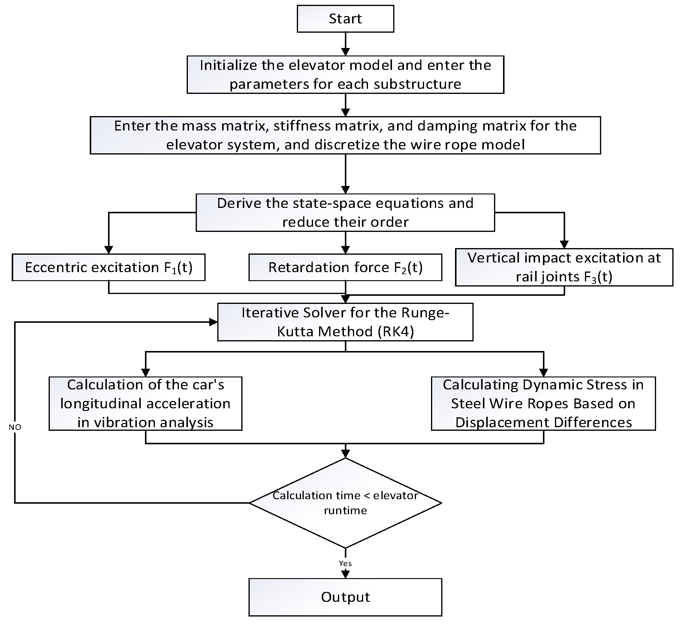
This flowchart illustrates the comprehensive numerical computational workflow for the analysis of longitudinal vibration and dynamic hoisting rope stress in high-speed elevators. It adheres to the dynamic simulation paradigm of ‘substructure modeling—multi-source excitation—iterative solving—response output.’ The process initiates with the initialization of the model and substructure parameters, followed by global matrix assembly and the transformation and order reduction in state-space equations. Subsequently, three core excitations—traction sheave eccentricity, braking torque, and rail joint impact—are loaded. The system is solved via the variable step-size fourth-order Runge–Kutta (RK4) method, enabling the parallel calculation of car longitudinal acceleration and dynamic rope stress, the latter serving as a key indicator of structural integrity. Upon completing iterations for the full operational cycle based on time-step criteria, the results are output, establishing a standardized computational framework for the quantitative evaluation of high-speed elevator dynamic characteristics.
Equation for calculating the dynamic stress in a steel wire rope in
Figure 8:
where,
denotes Young’s modulus;
is the relative displacement difference between adjacent nodes solved by the fourth-order Runge–Kutta method (RK4);
represents the unit length of the discrete segment of the steel wire rope. The calculation process is shown in
Figure 8:
4. Kinetic Responses to External Excitation
4.1. Analysis of Vibration Response Under Eccentric Excitation of the Traction Sheave
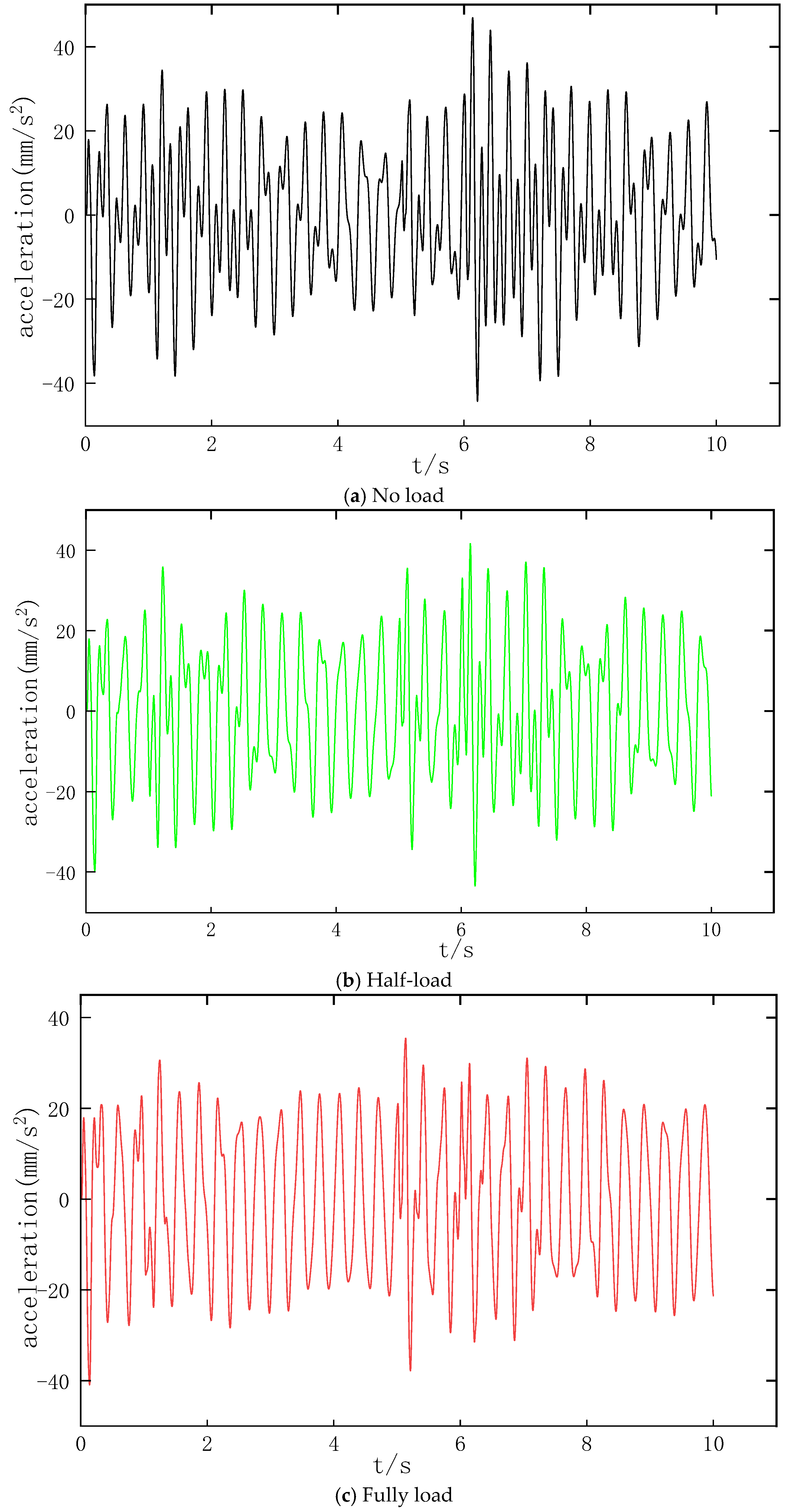
To investigate the impact of traction sheave eccentric excitation on the longitudinal vibration of the elevator car, an eccentricity of 3 mm is defined as the representative excitation source in this study. The time-domain responses of the longitudinal vibration acceleration of the car under three typical operating conditions—no-load, half-load, and full-load—are illustrated in
Figure 9.
As illustrated in
Figure 9, the car acceleration under traction sheave eccentric excitation exhibits distinct periodic fluctuations. An increase in payload leads to a significant reduction in peak-to-peak (P-P) acceleration: from 46.6 mm/s
2 under no-load to 40.8 mm/s
2 under half-load (a 12.5% attenuation), and further to 35.3 mm/s
2 under full-load (a 13.4% attenuation). Under the full-load condition, the increased total mass of the car enhances the system’s inertia and damping characteristics, which effectively buffer the impact of eccentric excitation, resulting in the most stable and smoothest acceleration response. From the perspective of equivalent vibration transmissibility, the natural frequency
of the system decreases as the car mass M increases. Given that the eccentric excitation frequency
of the traction sheave remains constant, the reduction in natural frequency leads to an increase in the frequency ratio
. Consequently, the operating point of the system’s forced vibration shifts deeper into the mass-controlled region, resulting in a sharp decline in vibration transmissibility.
4.2. Vibration Response of an Elevator During Upward Travel Under Eccentric Excitation
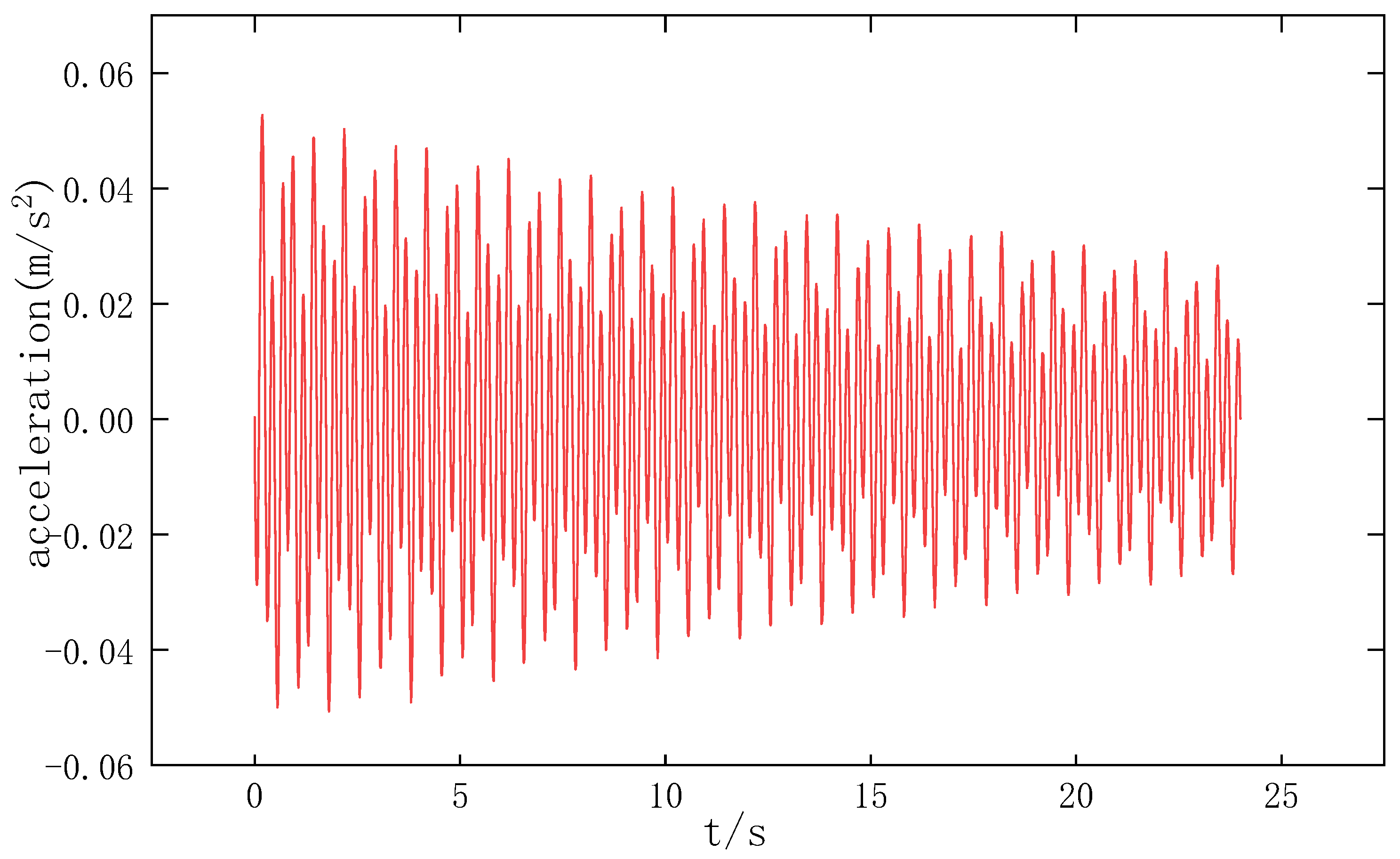
The longitudinal vibration time-domain response of the traction system during the upward travel under the half-load condition is illustrated in
Figure 10. It can be observed from
Figure 8 that as the elevator ascends, the length of the car-side wire rope continuously decreases, leading to a progressive increase in the system’s equivalent stiffness and an enhanced constraint on vibration. Consequently, under identical external excitations, the longitudinal vibration amplitude exhibits a gradual decreasing trend during the upward process.
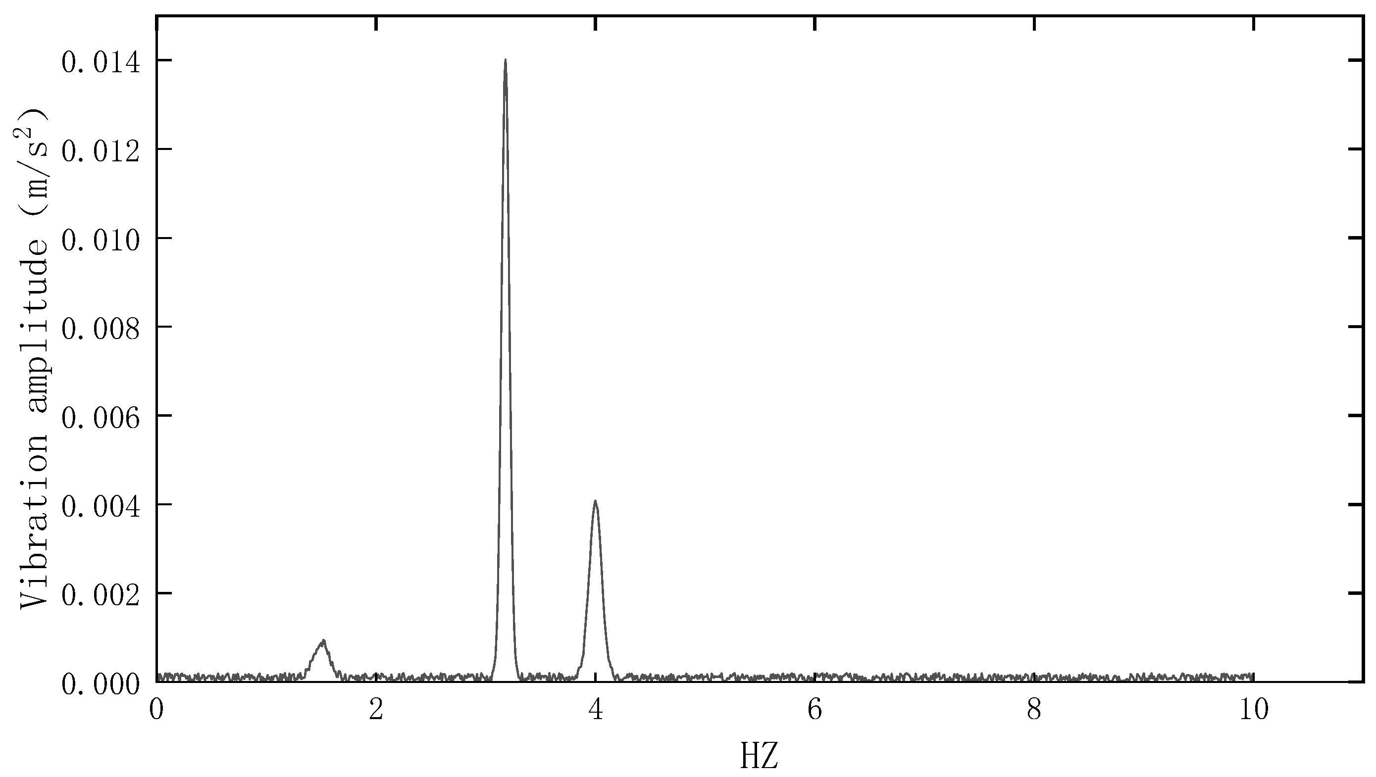
As illustrated in the spectral analysis in
Figure 11, the dynamic response of the system exhibits a pronounced peak. Based on the kinematic parameters of the hoisting system, the theoretical rotational frequency of the traction sheave can be calculated as
, where v = 6 m/s is the steady-state velocity and r = 0.3 m is the sheave radius. This yields a theoretical excitation frequency of 3.18 Hz. The FFT results in
Figure 11 reveal that the dominant frequency of the car’s longitudinal vibration aligns precisely with this 3.18 Hz theoretical value. This confirms that the periodic eccentric excitation from the traction machine’s rotation is the primary source of the dominant vibration, whereas the secondary peak around 4 Hz corresponds to the structural fundamental frequency of the MDOF system.
4.3. Vibration Response Under Reverse Braking Force Excitation
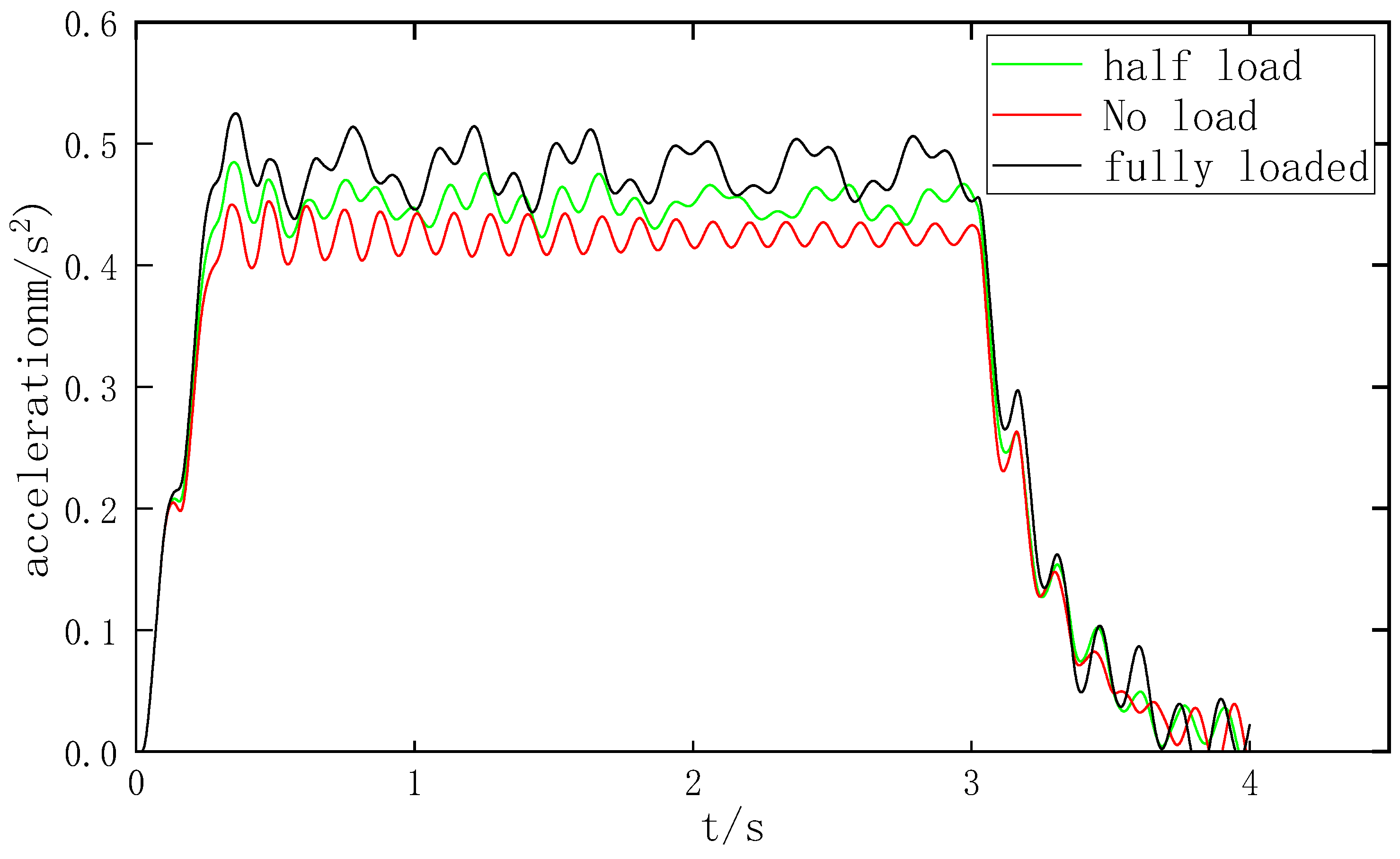
To investigate the impact of reverse braking force excitation on the longitudinal vibration of the elevator car, as illustrated in
Figure 12, the acceleration undergoes continuous oscillation within the range of 0.4 to 0.5 m/s
2 during the steady-state vibration phase. The oscillation amplitude is most pronounced under the full-load condition, followed by the half-load and no-load conditions in decreasing order, with the full-load condition also exhibiting a slightly higher peak value. This phenomenon reflects the discrepancies in the system’s steady-state vibration characteristics under various loading scenarios.
As the payload increases to the full-load state, the inertia on the car side is significantly enhanced, resulting in a peak acceleration approximately 15% higher than that in the no-load condition. Under full-load capacity, the immense inertia associated with the massive car mass strongly resists abrupt velocity fluctuations. When the traction sheave decelerates instantaneously, this substantial inertia generates a drastic transient tension differential in the wire ropes between the sheave and the car. According to D’Alembert’s principle, a larger mass induces stronger transient inertial forces, causing the suspension ropes to be excessively stretched; this subsequently triggers a greater acceleration overshoot during the tension rebound phase. Furthermore, as the load transitions from no-load to full-load—given that the structural damping coefficients C from the car-bottom rubber isolators and system friction remain relatively constant—the effective modal damping ratio of the car’s longitudinal primary mode undergoes significant relative attenuation. This exacerbated underdamped characteristic directly impairs the system’s capacity to dissipate transient shock energy, thereby preventing the transient response from converging rapidly.
4.4. Vibration Response of Guide Rail Joints Under Vertical Impact Excitation
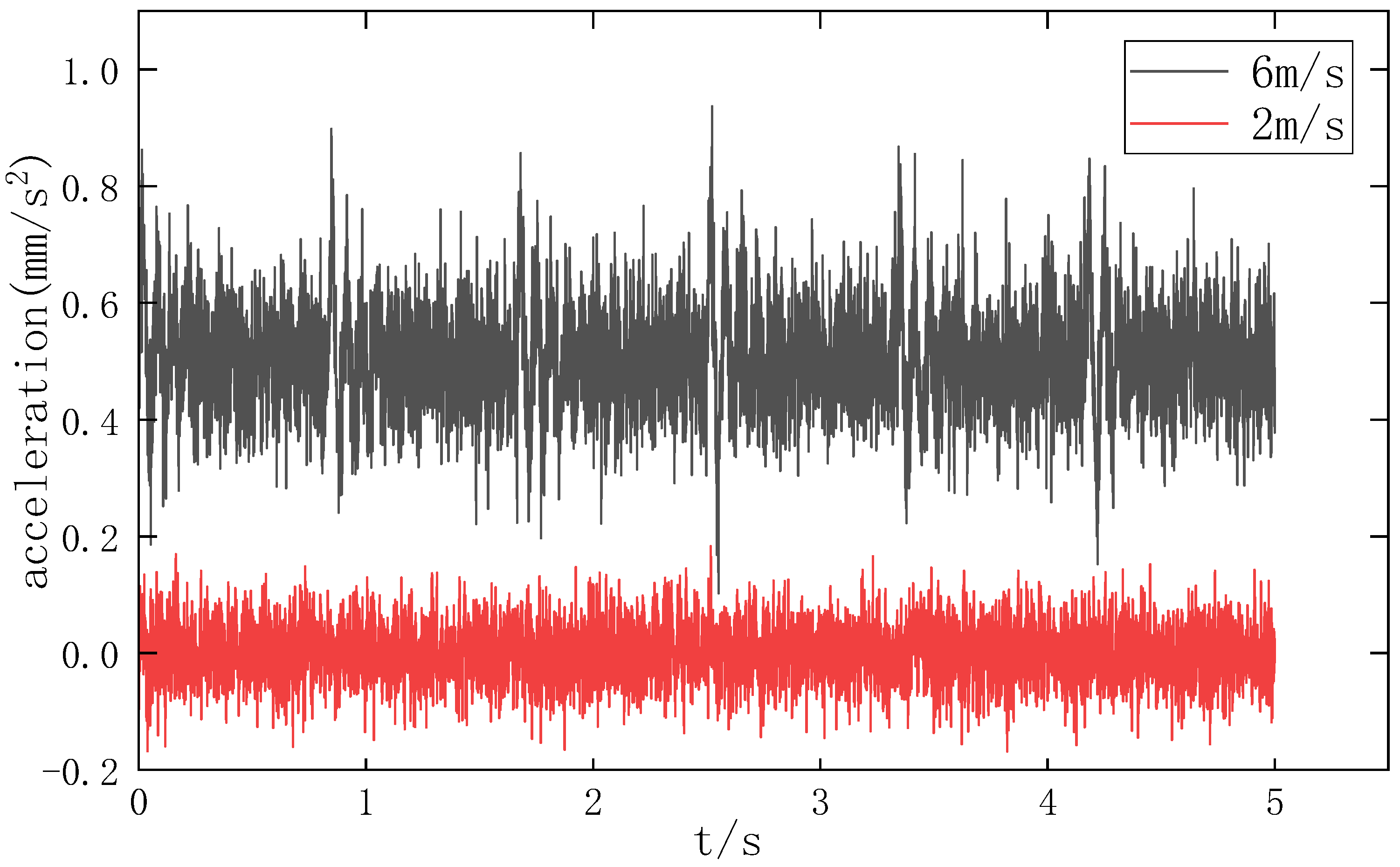
To investigate the impact of vertical impact excitation from guide rail joints on the longitudinal vibration of the elevator car, and to obtain more pronounced comparative results, this study selects 2 m/s and 6 m/s as representative velocities based on the velocity classification standards in the Technical Specifications for Elevators. Simulation analyses are conducted during the constant-speed phase under the no-load condition, with the results illustrated in
Figure 13.
As illustrated in
Figure 13, the rail joint impact induces distinct impulse spikes and short-duration damped oscillations in the car acceleration. Comparative analysis reveals that as the operating velocity increases, the acceleration exhibits periodic impacts, and the instantaneous peak magnitude rises accordingly. The unevenness of the rail joint can be characterized as a displacement step excitation. As the operating velocity
v increases, the time interval for the guide shoes to traverse the joint is significantly reduced. According to the impulse-momentum theorem, given a constant displacement amplitude, the extremely short contact duration leads to a sharp increase in the gradient (i.e., jerk) and peak of the instantaneous impact force
F, thereby triggering a more violent transient acceleration response in the car system. Furthermore, under high-speed impact conditions, the vibration-isolation rubber at the car bottom and the guide shoe liners exhibit nonlinear dynamic characteristics. The “impact hardening” effect at high strain rates causes a relative decrease in the effective damping ratio of the system, weakening its filtering capability for high-frequency shock waves and allowing the impact energy to be transmitted more directly to the car interior.
4.5. Dynamic Stress Analysis of Steel Wire Ropes
As the primary medium for power transmission in high-speed elevators, steel wire ropes are subjected to substantial stress during operation.
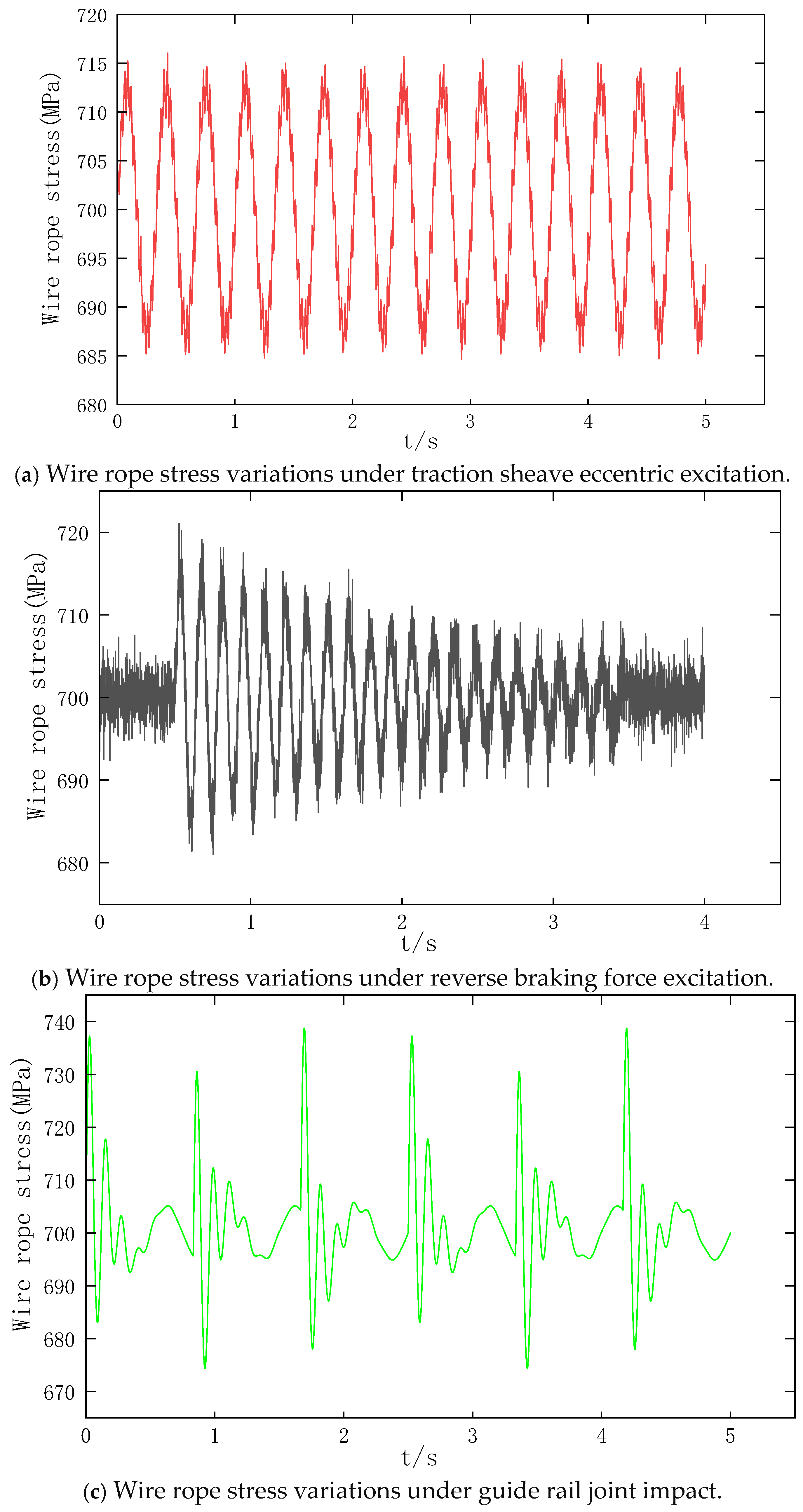
Figure 14 illustrates the dynamic stress response of the wire ropes under the combined influence of a full-load condition and external excitations. As observed, the peak instantaneous dynamic stress reaches approximately 680–740 MPa. It should be emphasized that these values represent the most severe dynamic transient responses rather than steady-state operating stresses.
To evaluate the risk of yielding, these peak values were compared with the material properties of Grade 1770 wire ropes. Given a nominal tensile strength of 1770 MPa, the lower bound of the yield strength is typically estimated at 60–65% of this value, or approximately 1100 MPa. Consequently, the peak stress of 740 MPa remains within the linear elastic region; even under these extreme impact pulses, a safety margin of approximately 1.5 relative to the yield point is maintained. These results demonstrate that the system preserves its structural integrity and avoids plastic deformation when traversing rail discontinuities at high speeds under full-load conditions.
However, it should be noted that relying solely on the comparison between instantaneous stress peaks and material yield strength is insufficient for a comprehensive evaluation of the long-term service safety of hoisting ropes. For such open-type flexible load-bearing structures, failure typically originates from cumulative high-cycle fatigue effects under multi-source excitations. By integrating dynamic stress analysis methods, the stress cycle characteristics of hoisting ropes under both periodic excitations (sheave eccentricity) and impact excitations (rail joints) can be further evaluated, enabling the identification of potential fatigue hot spots. Particularly under the coupling of multiple excitations, localized stress concentrations and frequent alternating loads may lead to the initiation and propagation of micro-cracks. Therefore, the introduction of fatigue assessment methods based on dynamic response is of paramount significance for enhancing the reliability analysis of critical components in elevator systems.
The effects of the three typical external excitations on the dynamic stress of the steel wire rope exhibit differentiated time-domain evolutionary characteristics, which correspond to distinct fatigue damage mechanisms.
Under Reverse Braking Torque Excitation: As shown in
Figure 14a, the wire rope stress presents typical characteristics of a transient impact followed by oscillatory decay. At the exact moment of braking intervention, the stress undergoes a drastic and sudden change, with an instantaneous peak-to-valley difference exceeding 40 MPa, while simultaneously exciting the low-order natural modes of the system. Although the stress peak of a single impact does not exceed the nominal tensile strength of the wire rope and satisfies the safety factor design requirements, the repeated braking actions throughout the elevator’s life cycle subject the wire rope to long-term alternating loads. This serves as a key inducement for localized fatigue damage.
Under Traction Sheave Eccentric Excitation: As illustrated in
Figure 14b, the wire rope stress exhibits continuous, constant-amplitude periodic fluctuations throughout the entire travel stroke. The stress fluctuation amplitude is significantly and positively correlated with the eccentricity of the traction sheave, yielding a single-cycle peak-to-valley difference that can reach 50 MPa. Distinct from the short-term, high-intensity excitation characteristics of the braking impact, the continuous alternating stress induced by eccentric excitation is the core cause of high-cycle fatigue, strand wear, and the initiation and propagation of microcracks in the wire rope.
Under Guide Rail Joint Impact Excitation: As depicted in
Figure 14c, the wire rope stress demonstrates high-frequency, discrete instantaneous spike characteristics. The peak-to-valley stress difference in a single impact can exceed 60 MPa, and the stress fluctuation amplitude increases significantly with the elevation of the elevator’s travel velocity. Such high-frequency, small-amplitude impacts are critical factors that accelerate the aging of the wire rope strands and diminish their overall service life.
From the perspective of structural design, the vibration peaks and dynamic hoisting rope stress responses identified in this study are inherently linked to the system’s mass distribution and structural stiffness characteristics. Based on the multi-stage topology optimization method, the material distribution of the elevator car frame and key traction system components can be reconstructed. This optimizes the primary load-bearing paths, thereby mitigating local vibration amplification effects. Specifically, under traction sheave eccentricity excitation and braking impacts, the optimized structure can effectively suppress vibration peaks by enhancing stiffness efficiency and reducing inertia coupling effects. Furthermore, the integration of lightweight materials is of significant importance. By employing high-specific-stiffness composite materials, such as Glass Fiber Reinforced Polymer, structural mass can be reduced while maintaining the required stiffness. This significantly decreases system inertia, subsequently lowering the amplitude of dynamic loads acting on the hoisting ropes, which serves a positive role in suppressing stress sensitivity in low-load ranges and delaying fatigue damage. Therefore, combining multi-stage topology optimization with lightweight material design strategies holds the potential to improve the dynamic response characteristics of elevator systems from a structural origin, providing a novel design paradigm for vibration control.
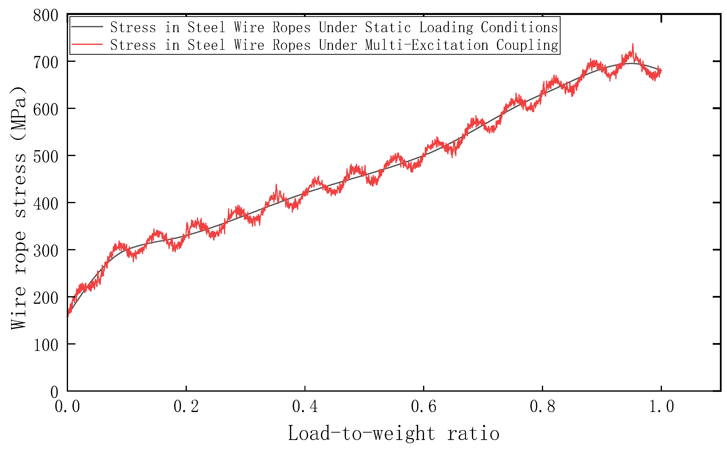
As can be seen from
Figure 15, the gray curve represents the steel wire rope stress under free vibration. This condition neglects the interference of external excitations, reflecting the stress baseline under the static load of the car solely. In contrast, the smooth, spline-fitted red curve illustrates the steel wire rope stress under multi-excitation coupling. By superimposing the three typical external excitations investigated in this study, it accurately replicates the authentic dynamic stress state during actual elevator operation.
Furthermore,
Figure 15 indicates that the stress variation is significantly more sensitive in the low-load range. During the low-payload phase with a load ratio between 0 and 0.2, the stress escalates rapidly from approximately 150 MPa to 300 MPa, demonstrating a highly pronounced response to payload variations in this regime. Conversely, in the high-load range of 0.8 to 1.0, the growth rate of the stress tends to level off, although it maintains an overall upward trajectory.
4.6. Comprehensive Comparison of the Effects of External Excitation Sources on System Response
To quantitatively evaluate the influence of each excitation source on the dynamic characteristics of high-speed elevators, this section selects an operating speed of 6 m/s as the baseline working condition and conducts a summarized comparison of the system responses under three types of excitations. The results are shown in
Table 4.
The analysis results indicate that braking torque and rail joint impact induce higher-magnitude acceleration responses compared to traction sheave eccentricity. However, rail joint impact poses the most significant threat to the structural integrity of the ropes, generating peak stresses up to 740 MPa. While this impact is transient, its high-strain-rate nature necessitates rigorous evaluation of the dynamic safety factor. In contrast, sheave eccentricity is a steady-state source that primarily affects long-term passenger comfort. This unified comparison suggests that vibration mitigation strategies should be prioritized based on the specific design goal: enhancing sheave precision for comfort versus improving rail alignment and rope damping for safety.