2. Design and Structural Analysis of UHV Shunt Reactors
The present study considers a single-phase UHV shunt reactor of type RSO-60000/500, which is widely used in high-voltage power systems for reactive power compensation and voltage stabilization. The reactor consists of a magnetic core, windings, yokes, and a steel tank filled with insulating oil. The main reactor parameters are summarized in
Table 1. The magnetic system is formed by laminated electrical steel sheets arranged into a core column and yokes, while the structural configuration includes supporting elements and a rigid tank enclosure.
The operation of UHV shunt reactors is associated with significant vibration and noise generation, primarily caused by magnetostriction of electrical steel and electromagnetic forces acting within the magnetic system. Magnetostriction leads to periodic deformation of the core material under alternating magnetic flux, whereas electromagnetic forces arise due to Maxwell stresses between adjacent structural components [
7,
8,
9,
10]. These excitation mechanisms result in the transmission of vibrations from the active part of the reactor to the tank, which subsequently acts as a radiating surface for acoustic emission.
To mitigate vibration and noise levels, a combination of damping techniques and structural modifications is proposed. Elastomeric damping elements made of nitrile butadiene rubber (NBR) are introduced into the magnetic system to reduce vibration transmission. These elements are installed between structural components of the core, effectively segmenting the active part and dissipating vibrational energy. The choice of NBR is determined by its high resistance to transformer oil and its stability at operating temperatures up to 110 °C. The implementation of damping layers reduces the stiffness of vibration transmission paths and contributes to the attenuation of structural oscillations.
In addition to damping measures, structural reinforcement of the reactor tank is applied to improve its dynamic performance. Vertical and horizontal stiffeners are incorporated into the tank walls to increase overall structural stiffness. This approach allows shifting the natural frequencies of the structure and reducing resonance effects under harmonic excitation, particularly in the low-frequency range typical for UHV reactor operation.
To evaluate the effectiveness of the proposed solutions, a finite element model of the reactor tank is developed. The model includes shell and solid elements representing the tank walls, internal components, and support conditions, as well as contact elements to simulate interactions between structural parts. The tank is subjected to harmonic acoustic loading that represents excitation generated by the active part of the reactor. The analysis is performed in the frequency range of 50–150 Hz, corresponding to dominant operational frequencies. A damping ratio of 2% is assumed in the simulations, and boundary conditions are defined based on the support of the tank at its base to ensure realistic representation of operating conditions [
15,
16,
17,
18,
19].
The developed numerical model enables the assessment of vibration characteristics and provides a basis for analyzing the influence of structural modifications and damping techniques on the overall vibroacoustic response of UHV shunt reactors.
The manufacturing process of the magnetic system plays a crucial role in determining both the energy efficiency and vibroacoustic performance of UHV shunt reactors. A significant portion of vibration and noise originates from the magnetic core, where eddy current losses and magnetostrictive effects are dominant.
Eddy current losses can account for up to 70% of the total losses in cores made of anisotropic electrical steel. These losses not only reduce efficiency but also contribute to localized heating and additional mechanical stresses, which increase vibration levels. In parallel, magnetostriction of electrical steel causes periodic deformation of the core under alternating magnetic flux, generating dynamic excitation forces that are transmitted to the reactor structure.
To mitigate these effects, modification of the magnetic domain structure of electrical steel is required. Several techniques can be applied, including controlled grain orientation, mechanical surface treatment, and laser processing. Among these methods, laser surface treatment is considered one of the most effective non-contact approaches for reducing core losses and suppressing vibration and noise.
During laser processing, localized thermal heating induces residual stresses in the surface layers of the material, leading to refinement of magnetic domains and reduction in magnetization reversal losses. As a result, both eddy current losses and magnetostrictive deformation amplitudes are reduced. However, excessive thermal input may negatively affect magnetic properties, including a decrease in magnetic induction and damage to the insulating coating. Therefore, optimization of laser processing parameters is essential to achieve a balance between loss reduction and material integrity.
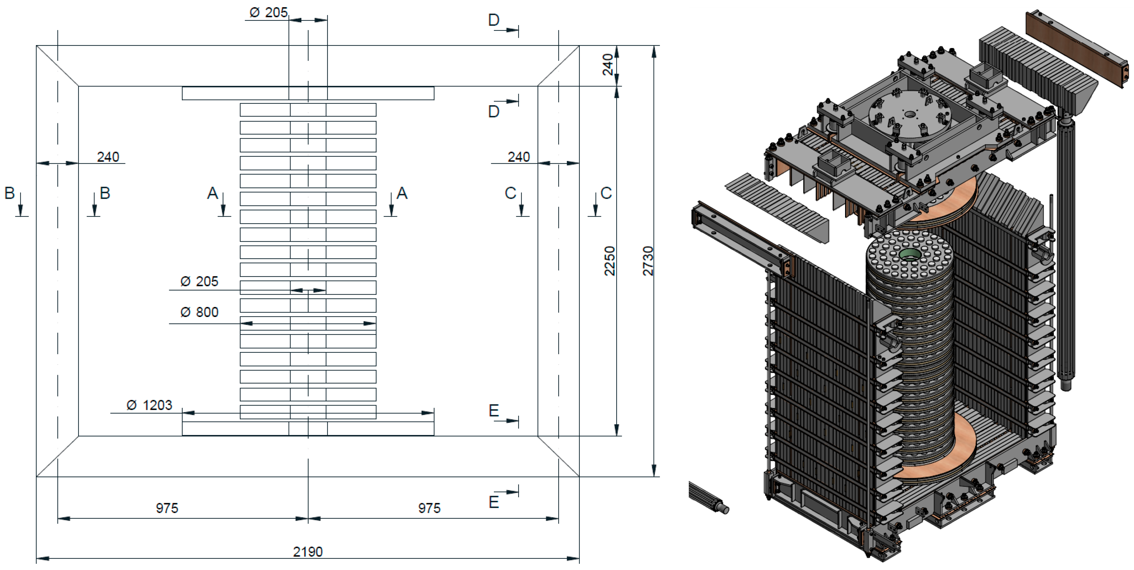
In this study, electrical steel grade M090-27Pb HIB is used for the magnetic core. The manufacturing process includes controlled laser treatment to improve magnetic properties and reduce vibroacoustic excitation. By decreasing the amplitude of magnetostrictive deformation and electromagnetic excitation at the source, the proposed approach contributes to lowering vibration transmission to the reactor tank and, consequently, reducing noise emission. The 3D model of the reactor is shown in
Figure 1. The main parameters of the magnetic circuit are summarized in
Table 2.
The vibroacoustic behavior of UHV shunt reactors is governed by coupled electromagnetic, structural, and acoustic phenomena. The primary sources of excitation originate from magnetostriction of electrical steel and electromagnetic forces acting within the magnetic system.
Magnetostriction causes periodic deformation of the electrical steel core under alternating magnetic flux. The magnetostrictive strain can be approximated as a function of magnetic flux density:
where (
λ) is the magnetostrictive strain, (
B) is the magnetic flux density, and (
k) is a material-dependent coefficient. This nonlinear relationship results in vibration components at twice the supply frequency.
In addition to magnetostriction, electromagnetic forces arise due to Maxwell stresses acting on the magnetic core. The normal component of electromagnetic pressure can be expressed as:
where (
p) is the electromagnetic pressure and (µ
0) is the permeability of free space.
These forces generate mechanical loads on the core structure and act as a source of vibration.
The structural response of the reactor tank to these excitation forces can be described by the dynamic equilibrium equation:
where (
M), (
C), and (
K) are the mass, damping, and stiffness matrices, respectively, (
u) is the displacement vector, and (
F(
t)) represents excitation forces induced by electromagnetic effects.
The vibrating surfaces of the reactor tank radiate sound into the surrounding medium. The acoustic pressure is related to the vibration velocity of the structure and can be estimated as:
where (
pac) is the acoustic pressure, (
p) is the medium density, (
c) is the speed of sound, and (
v) is the vibration velocity of the surface.
Thus, the vibroacoustic process in UHV shunt reactors can be represented as a coupled chain: magnetostriction and Maxwell stresses → structural vibration → acoustic radiation. These mechanisms form the theoretical basis for the numerical modeling and experimental validation presented in the following sections.
One of the key factors contributing to high vibration levels in UHV shunt reactors is the direct transmission of dynamic forces from the magnetic core to the tank structure through rigid mechanical connections. In conventional designs, these continuous structural paths allow magnetostrictive deformation and electromagnetic forces to propagate efficiently, resulting in increased vibration amplitudes and acoustic radiation.
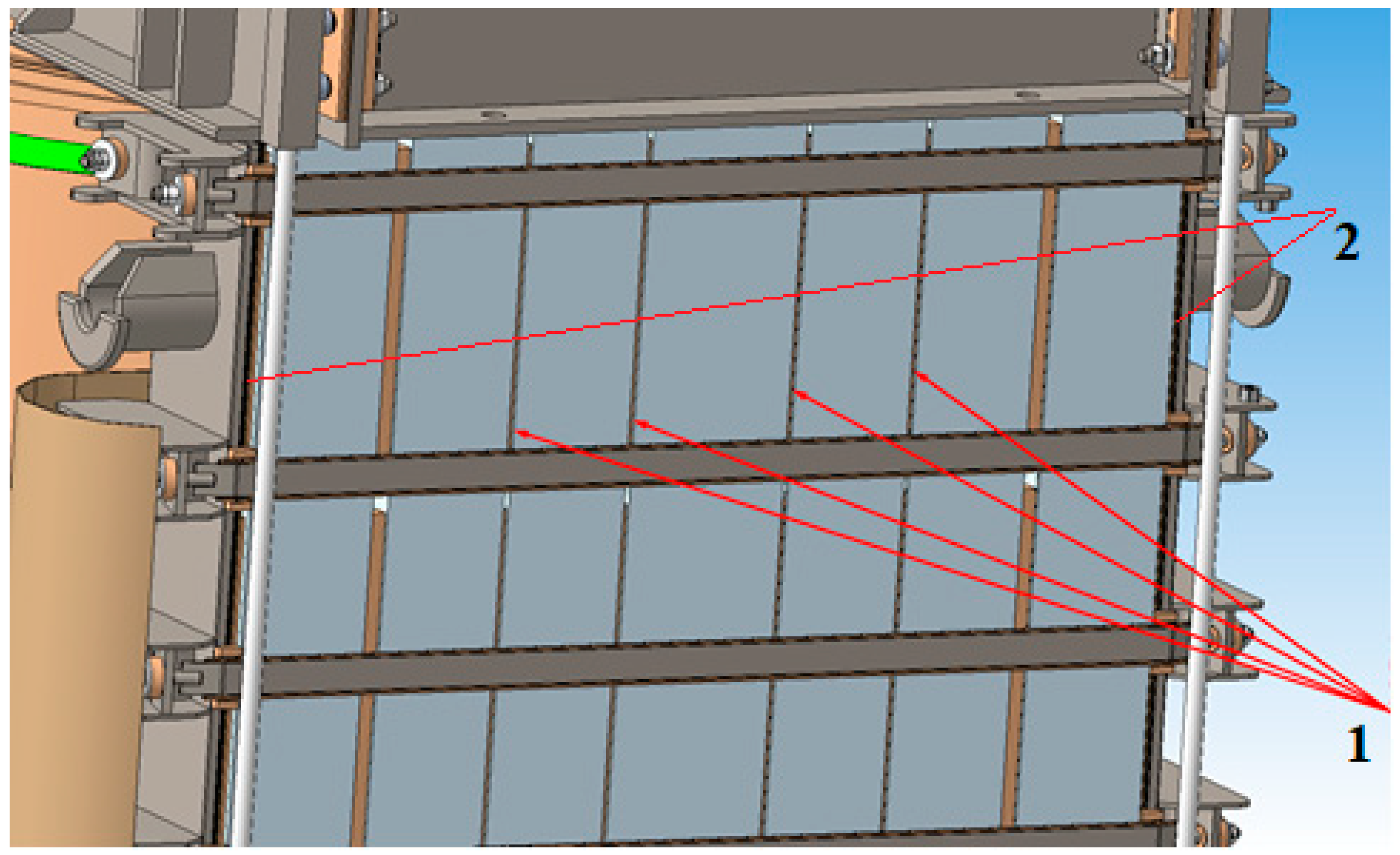
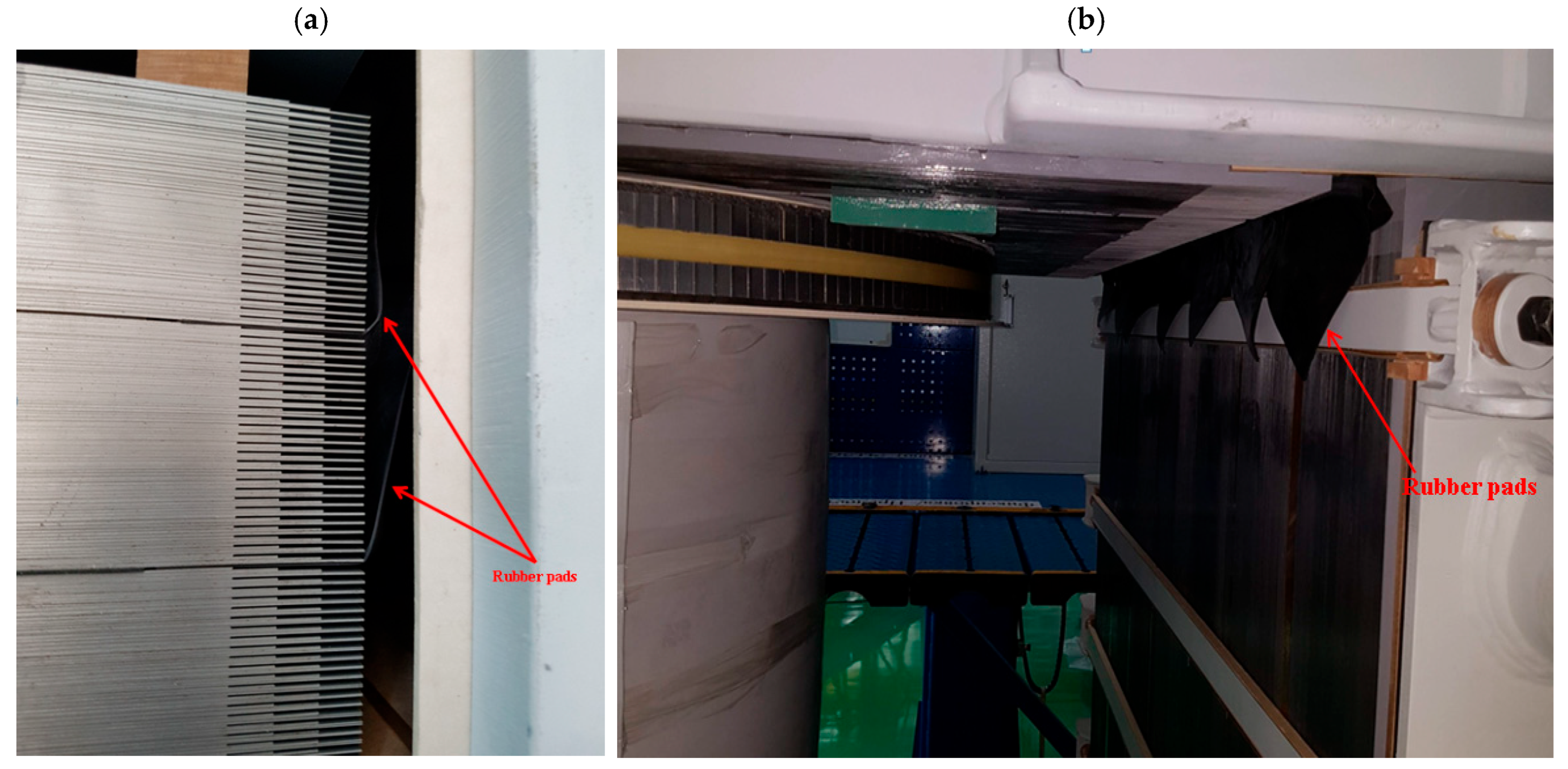
To mitigate this effect, elastomeric damping elements made of NBR are introduced into the magnetic system. The rubber gaskets are installed between core packets and structural components, as shown in
Figure 2 and
Figure 3, effectively interrupting vibration transmission paths and introducing additional damping into the system.
Due to their viscoelastic properties, NBR materials provide both elastic compliance and energy dissipation. Part of the mechanical vibration energy is converted into heat, which reduces the amplitude of transmitted oscillations. As a result, the effective stiffness of the vibration transmission path is reduced, and resonance effects are suppressed.
Furthermore, segmentation of the magnetic core using rubber layers reduces the coherence of vibration propagation and prevents amplification of oscillations at structural interfaces. This is particularly important in the low-frequency range associated with power-frequency excitation.
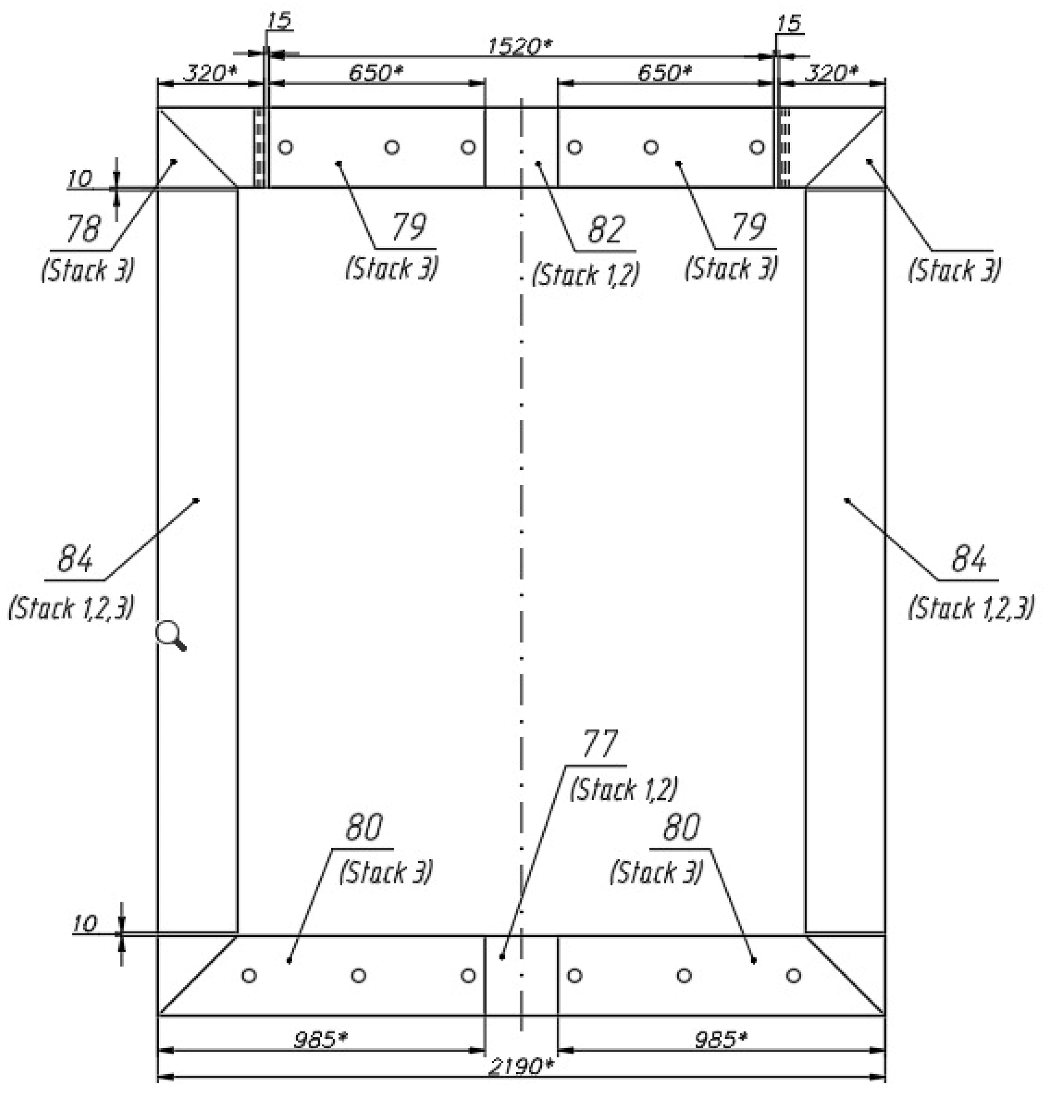
The practical implementation of rubber gaskets in the reactor structure is illustrated in
Figure 4, where the placement of damping elements between magnetic core packets and in the assembled reactor is presented.
The selection of gasket thickness, geometry, and placement depends on the structural configuration of the reactor core and the applied clamping forces. The material demonstrates high resistance to transformer oil and maintains stable mechanical properties at temperatures up to 110 °C, ensuring reliable long-term operation.
The implementation of rubber gaskets leads to a measurable reduction in noise levels of approximately 2–3 dB, as observed in experimental studies. The effectiveness of the proposed approach is further confirmed by the numerical and experimental results presented in the following section.
The operating thermal conditions of the reactor were verified based on temperature rise tests conducted in accordance with IEC standards. The results show that the maximum temperature rise in the top oil and winding does not exceed 52.5 °C and 58.6 °C, respectively, while the hottest spot temperature remains below 70 °C. These values are significantly lower than the allowable operating temperature range of NBR materials (up to 100–110 °C), ensuring stable damping performance and long-term reliability under transformer oil immersion. Furthermore, NBR materials are known for their resistance to mineral insulating oils and aging effects, which supports their suitability for long-term operation in UHV reactors. These results are based on experimental heating tests of the reactor.
The vibroacoustic analysis of the reactor tank requires evaluation of vibration amplitudes of the tank walls under harmonic excitation. The objective of the numerical model is to determine displacement distributions over a range of operating frequencies.
The geometric model of the reactor tank is developed taking into account the structural configuration of the active part, including the yoke, windings, disks, and supporting elements. Particular attention is given to the positioning of support points at the tank bottom, which significantly influences the dynamic response of the structure.
To ensure accurate representation of the real system, the finite element model was developed using TDS software (SoftTeamGroup, Zaporizhzhia, Ukraine). The numerical model is constructed using a combination of element types, including SHELL181 for tank walls, SOLID185 for structural components, PIPE59 for connecting elements, and TARGE170 and CONTA174 for contact interactions. This approach allows modeling both structural behavior and interaction between components.
The tank is modeled as a spatial shell structure reinforced by vertical and horizontal stiffeners. Increasing the number of stiffeners improves structural rigidity and reduces vibration amplitudes, as reported in previous studies [
16,
17,
18,
19]. In addition, the introduction of localized masses is used to adjust the frequency response of the system.
An acoustic domain is defined inside the tank to simulate sound pressure generated by the active part and its transmission through insulating oil to the tank walls. The model consists of two coupled regions: one in direct contact with the tank walls and another representing the internal active components. The acoustic–structural coupling approach used in this study is consistent with methods reported in previous works [
16,
17,
18,
19].
The insulating oil inside the tank is modeled as an acoustic medium, which allows consideration of the added mass effect and its influence on the structural response. This approach represents a simplified fluid–structure interaction (FSI) model suitable for vibroacoustic analysis in the frequency range of interest.
The excitation is applied as harmonic acoustic pressure acting on the inner surfaces of the tank. The equivalent load is taken as 364 Pa, corresponding to the estimated sound pressure level generated by the active part. The analysis is performed in the frequency range of 50–150 Hz, which corresponds to the dominant operational frequencies of UHV reactors.
A damping ratio of 2% is assumed in the simulations. The boundary conditions are defined by fixing the tank structure at the support locations corresponding to the bottom beams. These constraints ensure that the model adequately represents the actual installation conditions of the reactor.
For the harmonic steady-state analysis, the initial conditions were assumed to be zero initial displacement and zero initial velocity. This assumption is consistent with the formulation of a steady-state vibroacoustic problem, where the transient response is not considered and the structural response is evaluated under harmonic excitation.
The numerical model includes several simplifying assumptions, such as linear elastic material behavior, harmonic excitation, and equivalent representation of internal electromagnetic forces. These assumptions allow efficient analysis while preserving the dominant vibroacoustic characteristics of the reactor.
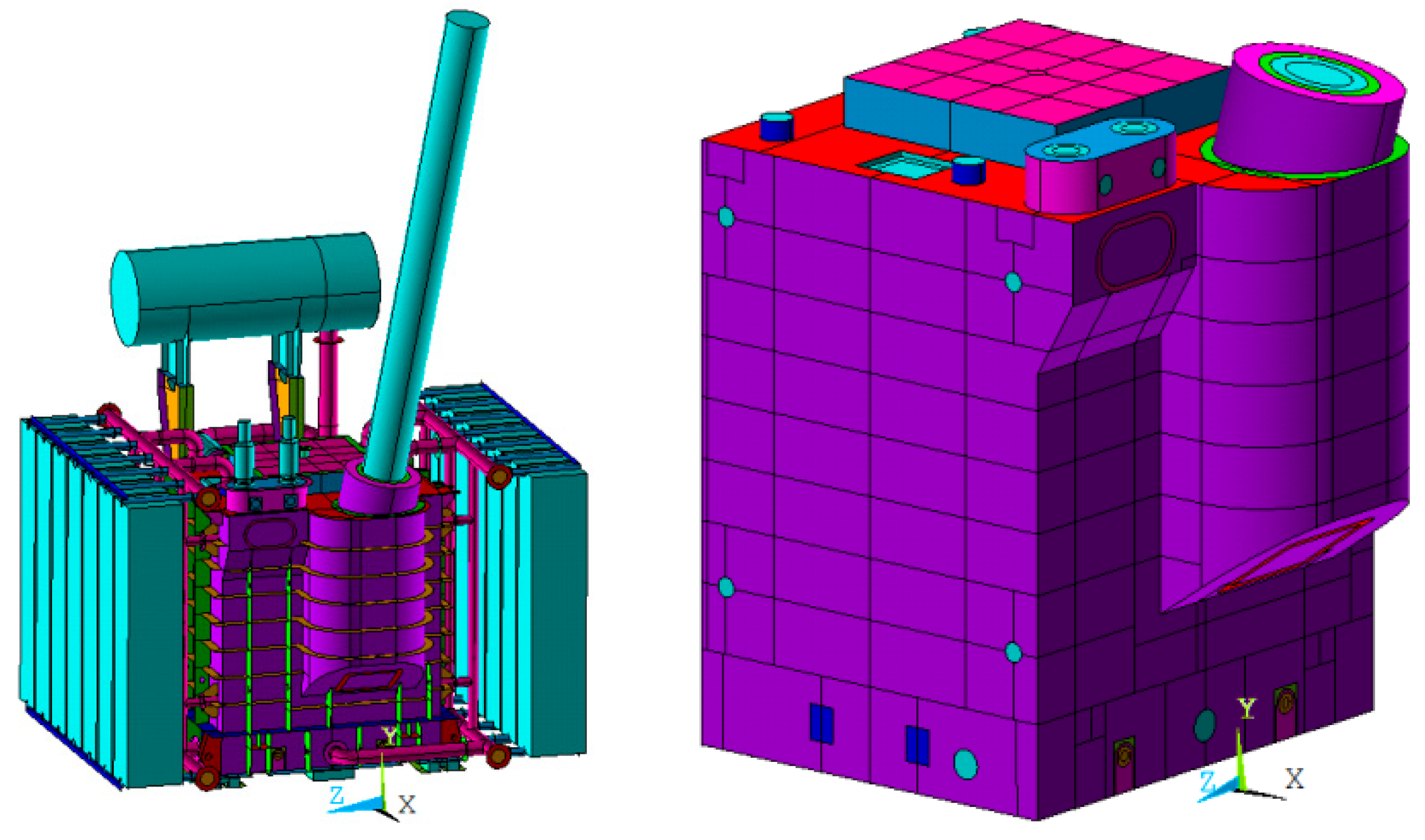
The developed model enables evaluation of vibration distribution and identification of critical zones with maximum displacement amplitudes. A representative finite element model of the reactor tank is shown in
Figure 5.
3. Results and Discussion
The vibroacoustic performance of the UHV shunt reactor was evaluated using both finite element analysis and experimental measurements. The obtained results are consistent with the theoretical model described in the previous section, where vibration excitation is governed by magnetostriction and electromagnetic forces associated with Maxwell stresses.
The finite element model was discretized using an appropriate mesh density to ensure accurate representation of structural behavior. The numerical model consists of approximately 120,000 finite elements and 185,000 nodes. Mesh refinement was applied in critical regions with high stress and displacement gradients to improve solution accuracy.
The finite element discretization was generated based on the detailed 3D geometric model of the reactor tank and internal structural components.
The selected discretization provides a balance between computational efficiency and numerical accuracy. This discretization approach ensures stable numerical results and is sufficient for capturing the dominant vibration characteristics of the reactor.
A mesh convergence assessment was performed by comparing displacement amplitudes obtained for different mesh densities. The variation in the calculated displacement amplitudes remained within acceptable engineering limits, indicating convergence and stability of the numerical solution. Further mesh refinement produced only minor changes in the calculated results.
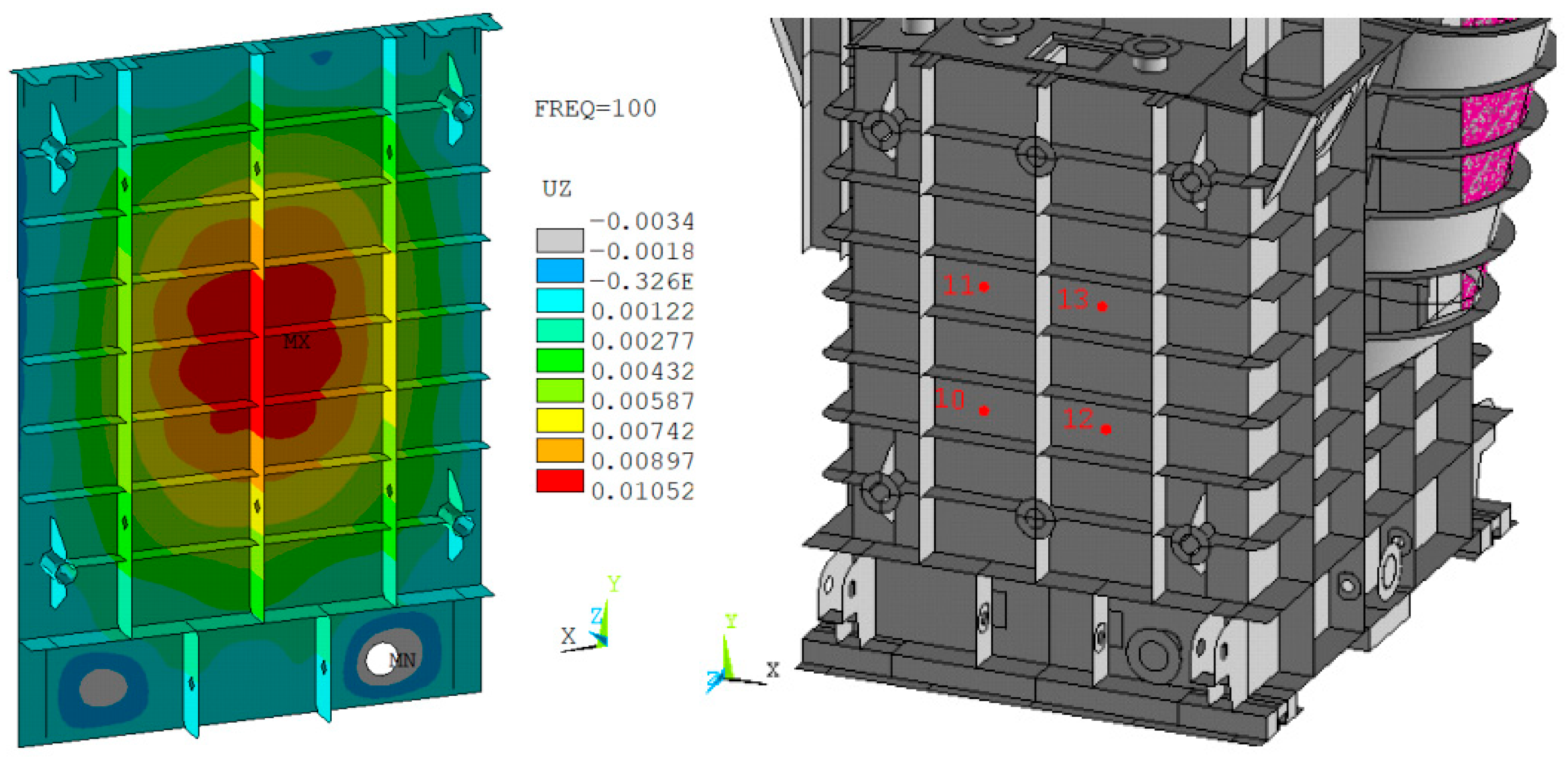
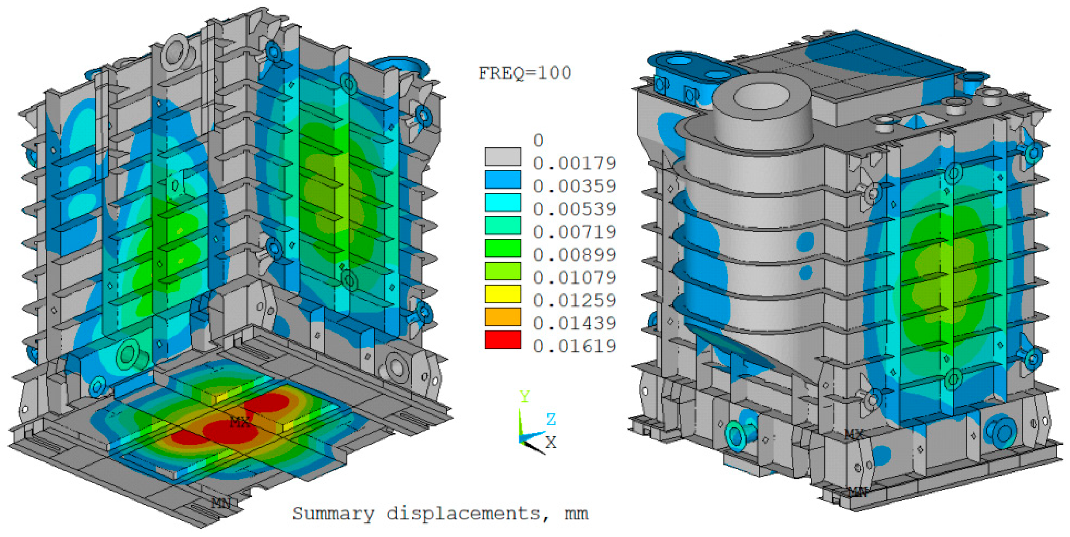
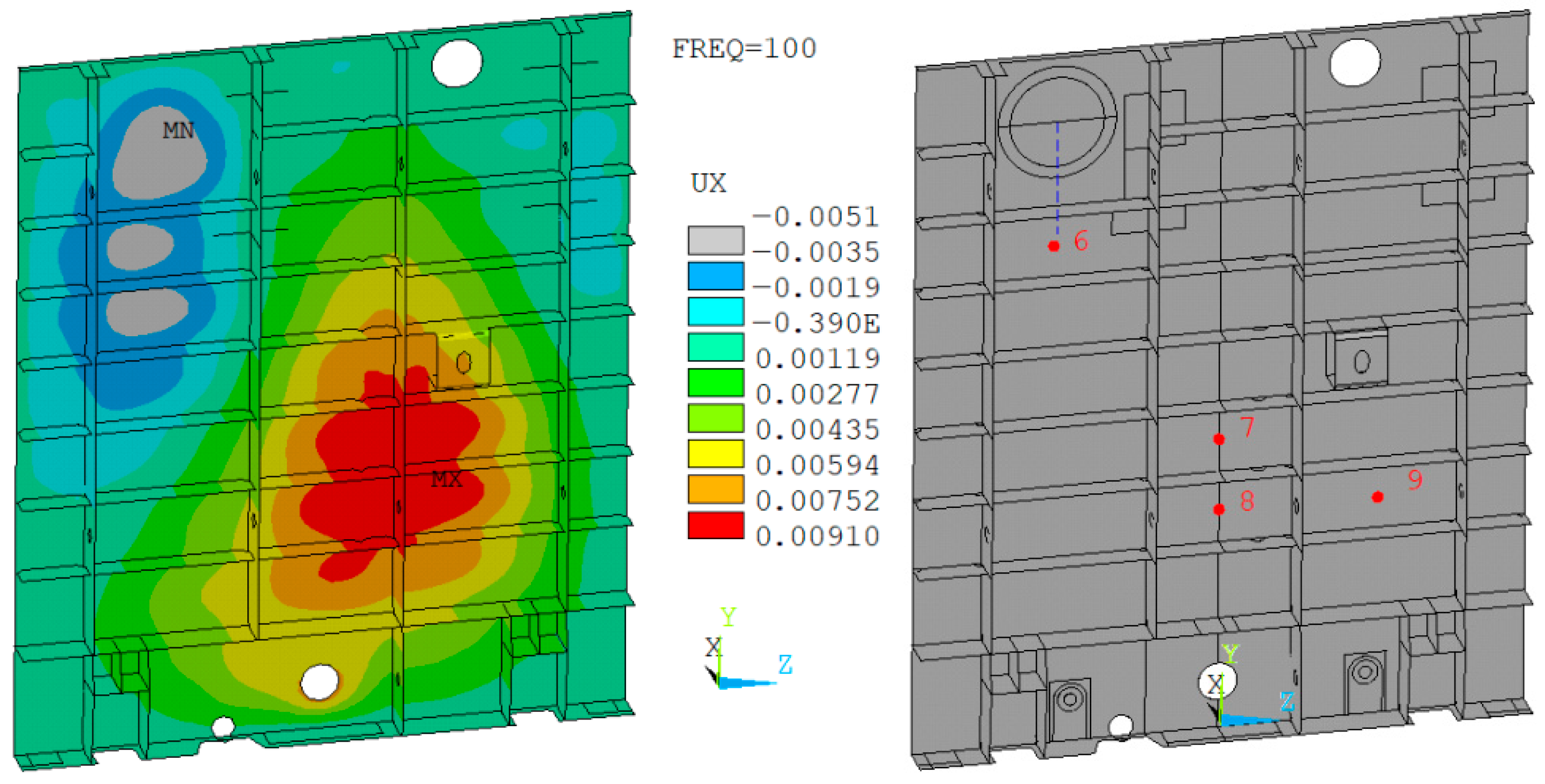
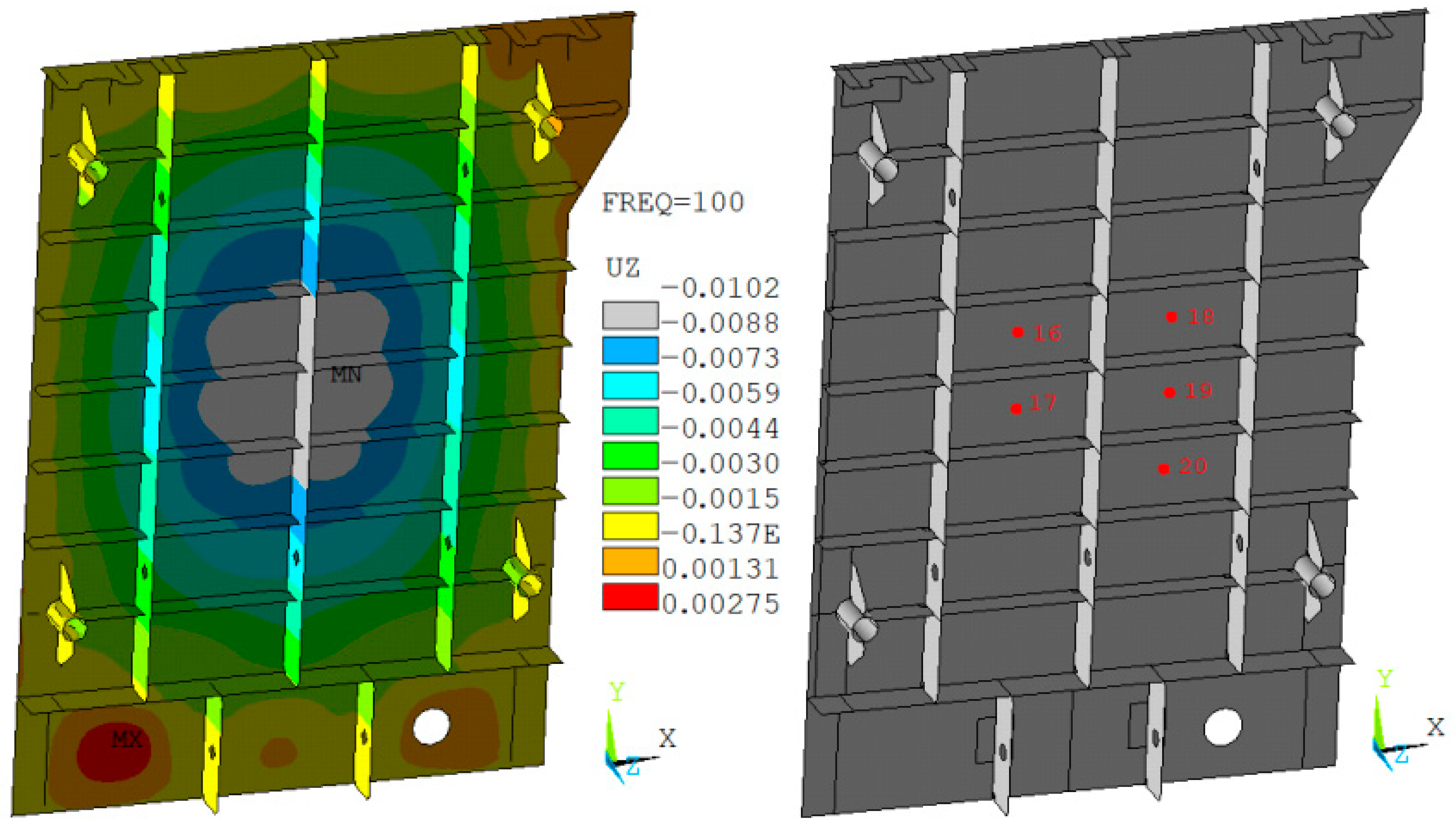
The numerical analysis shows that the maximum displacement amplitude of the reactor tank reaches 16.2 μm at the bottom and 10.5 μm at the tank walls, as illustrated in
Figure 6. These results indicate that the highest vibration levels occur in regions with lower structural stiffness and higher exposure to excitation forces.
The obtained results indicate that the highest vibration amplitudes occur in regions with lower structural stiffness and increased exposure to excitation forces. This behavior is consistent with the expected dynamic response of thin-walled structures subjected to harmonic loading.
The presence of resonance peaks within the frequency range of 50–150 Hz confirms the influence of structural natural frequencies on the vibration response. The proposed structural modifications effectively reduce these resonance effects by increasing stiffness and altering vibration transmission paths.
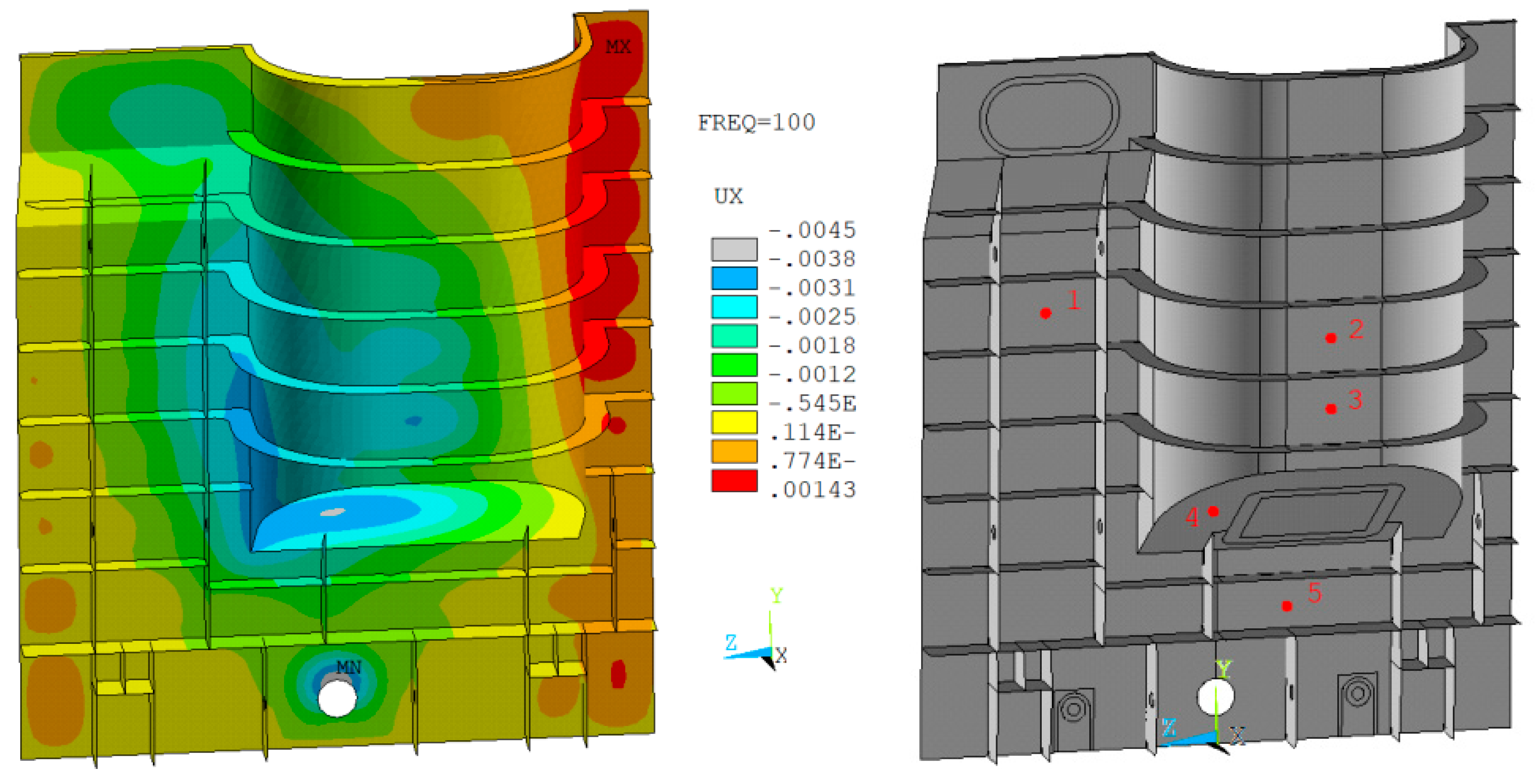
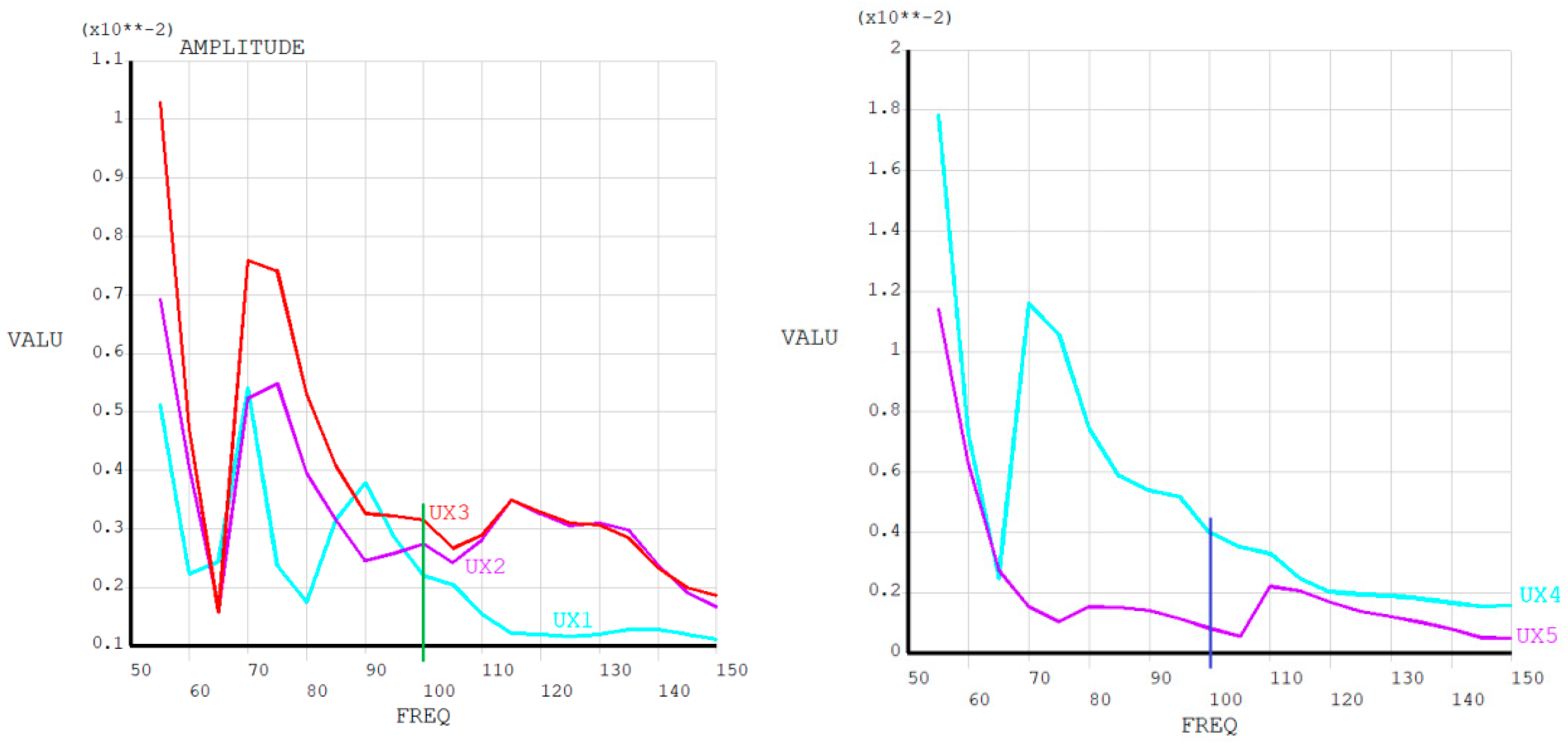
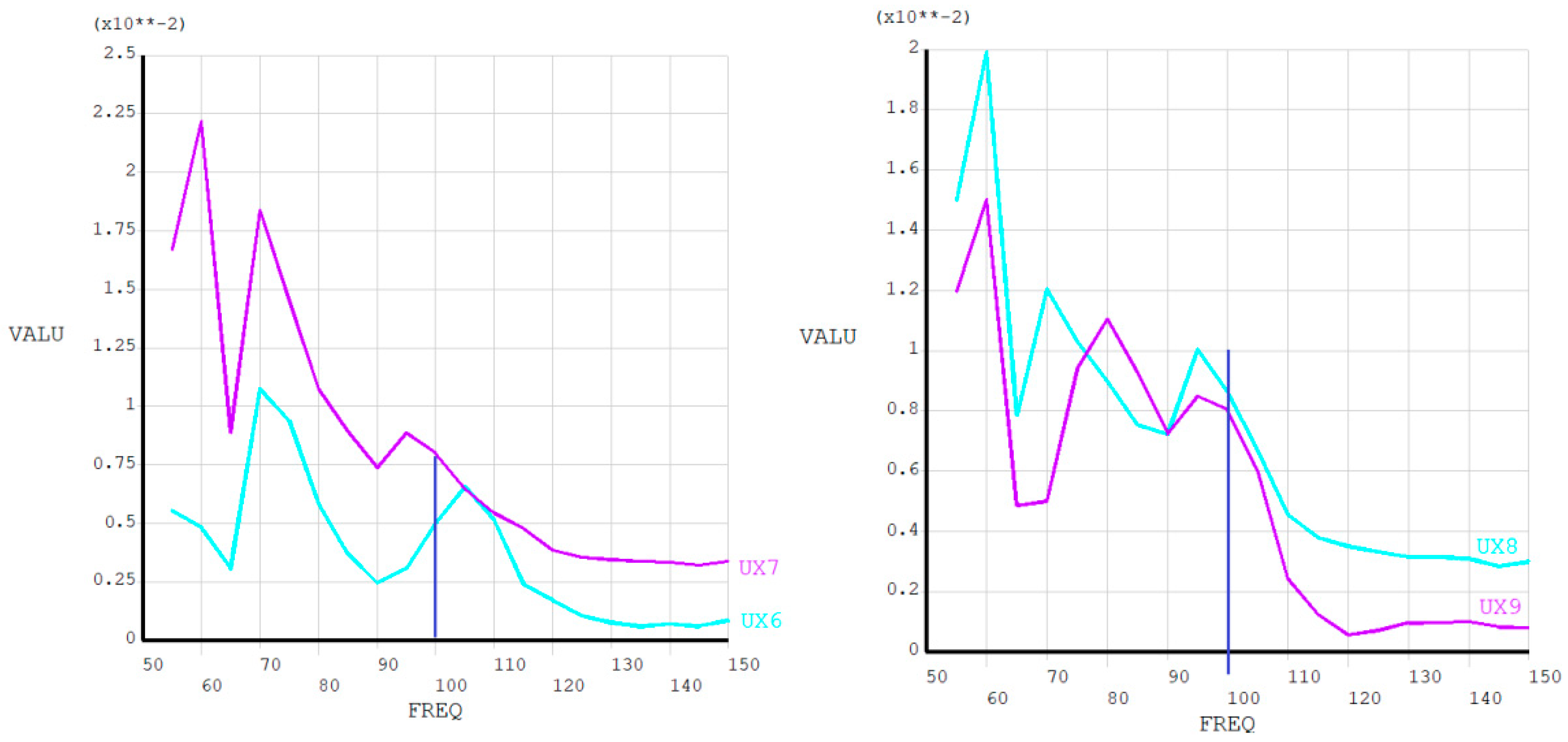
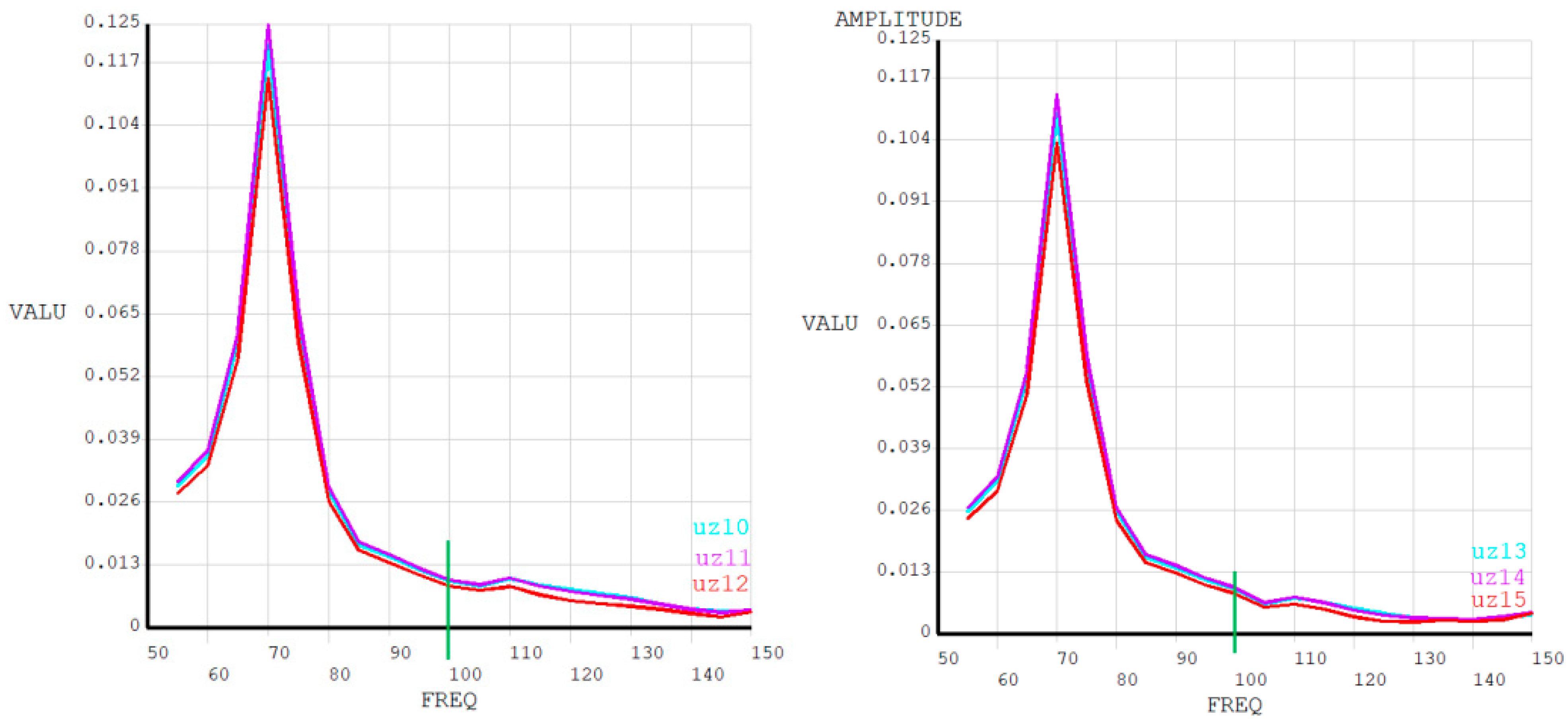
The spatial distribution of displacements at a frequency of 100 Hz is presented in
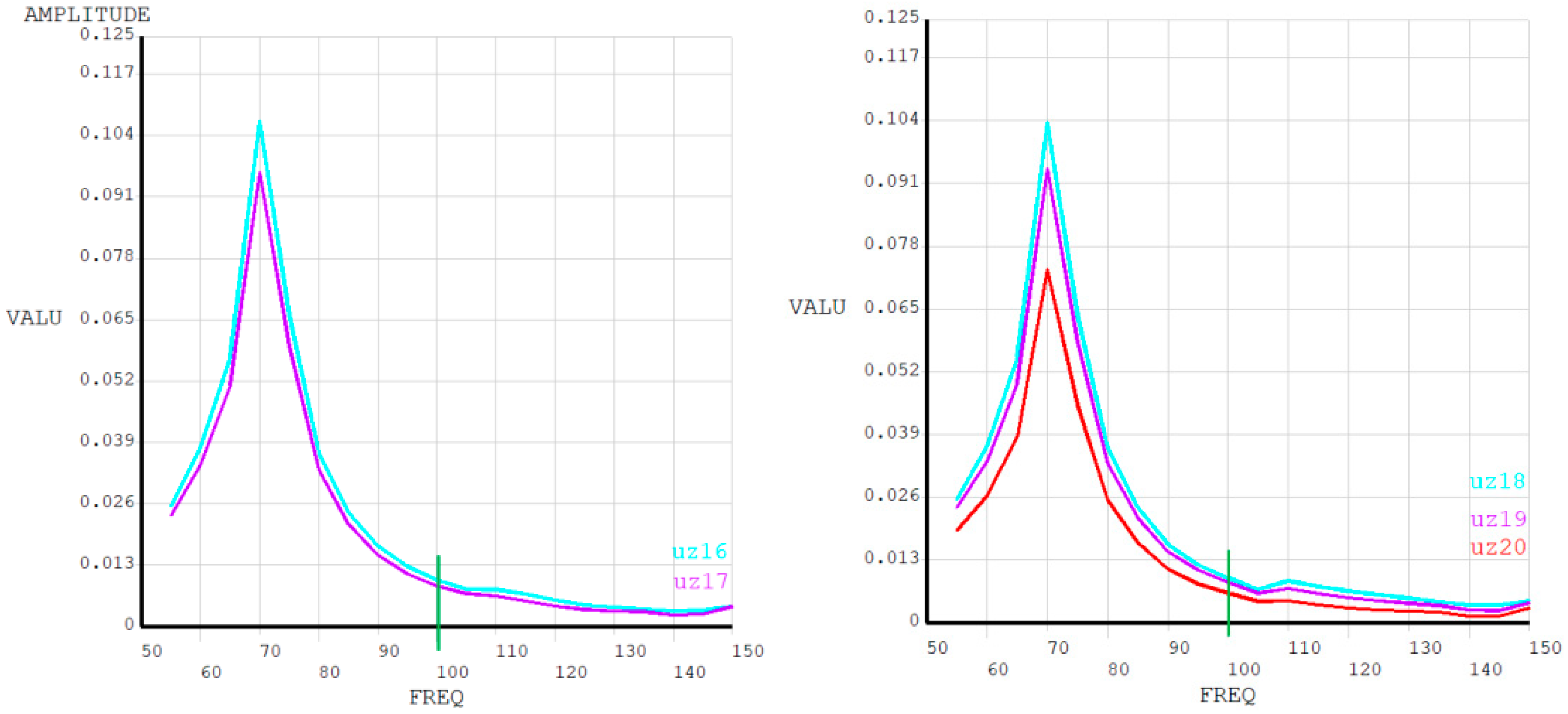
Figure 6, where the zones of maximum deformation are clearly identified. The frequency response analysis (
Figure 7,
Figure 8,
Figure 9,
Figure 10,
Figure 11,
Figure 12,
Figure 13 and
Figure 14) demonstrates that vibration amplitudes vary significantly across different points of the tank walls in the frequency range of 50–150 Hz. The displacement curves confirm the presence of resonance effects associated with the structural characteristics of the tank.
The implementation of structural reinforcement and damping techniques leads to a significant reduction in vibration transmission. In particular, the use of vertical and horizontal stiffeners increases the rigidity of the tank, while elastomeric NBR elements reduce the amplitude of transmitted vibrations by interrupting vibration paths.
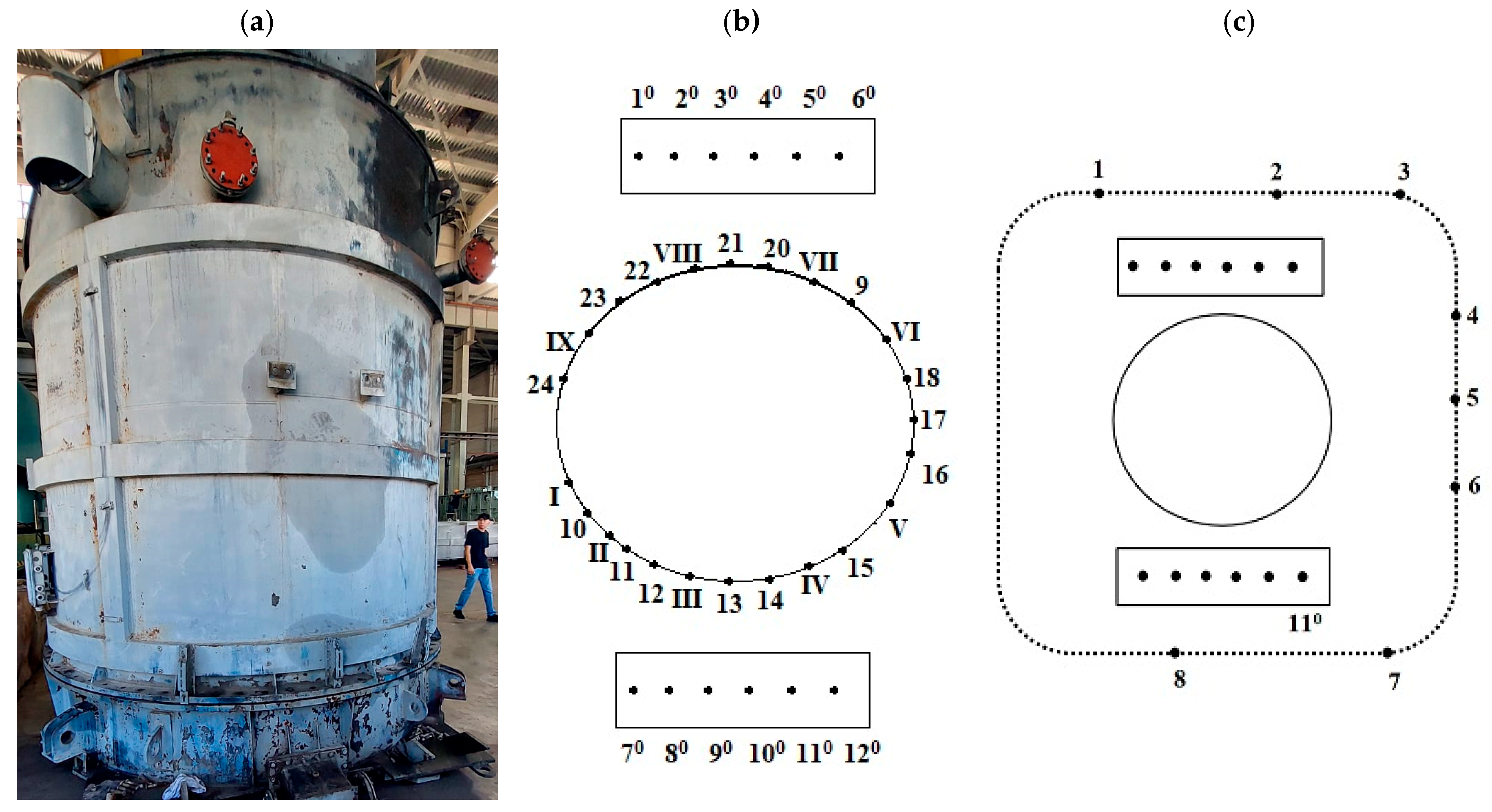
To further validate the effectiveness of the proposed design, a comparison was carried out using a single-phase RSFC-60000/500 reactor equipped with a forced cooling system. The geometrical dimensions of the reactor are 4.5 m in length, 5.0 m in width, and 4.8 m in height. The experimental setup and measurement locations are shown in
Figure 15. The experimental study was performed on the initial reactor design, which does not include NBR damping elements and has a reduced number of stiffeners. This configuration is used as a reference case for evaluating the effectiveness of the proposed structural optimization.
The sound level measurements are presented in
Table 3, while the frequency-dependent sound pressure levels are given in
Table 4. The results confirm that the overall sound power level of the reactor is 88 dBA, which satisfies the regulatory limit of 100 dBA. Noise measurements were conducted in accordance with IEC 60076-10, including consideration of background noise and environmental correction factors. Background noise levels were recorded during the measurements and corresponding corrections were applied to obtain accurate sound pressure levels of the reactor.
The measured vibration displacement values of the tank walls are summarized in
Table 5, showing that the maximum value does not exceed 13 μm, which is well below the permissible limit of 30 μm. For the cooling system, the measured vibration levels (
Table 6) do not exceed 4 μm, compared to the allowable limit of 60 μm. These results indicate stable vibration behavior across both primary and auxiliary components of the reactor. A comparison between numerical and experimental results shows that the discrepancy in vibration displacement does not exceed 20%, indicating good agreement and confirming the adequacy of the developed model.
The analysis of the frequency content of the noise signal shows that the dominant component corresponds to 100 Hz and its harmonics. These components are associated with magnetostriction effects and electromagnetic forces in the magnetic core. The implementation of damping elements and structural reinforcement contributes to the reduction in these frequency components. This behavior is consistent with typical vibroacoustic characteristics of power transformers and shunt reactors.
The numerical results correspond to the optimized reactor design, while the experimental measurements were performed on the initial configuration. Despite this difference, the comparison shows that the proposed structural modifications lead to a significant reduction in vibration levels.
These results confirm the effectiveness of the proposed structural modifications. The observed differences are associated with structural modifications, including the introduction of NBR damping elements and additional stiffeners, which alter the dynamic behavior of the system.
A comparison of the initial and modified configurations indicates that vibration amplitudes are reduced by up to 38%, while noise levels decrease by approximately 8 dB. These improvements confirm the effectiveness of the combined approach based on structural optimization and damping techniques.
In addition to vibroacoustic performance evaluation, impulse tests were conducted to verify the electrical strength of the reactor insulation. The results confirmed that the reactor withstands lightning and switching impulse voltages without insulation failure, demonstrating stable operation under high-voltage transient conditions. This indirectly supports the structural integrity and reliability of the proposed design.
Overall, the results confirm that reducing excitation transmission paths and increasing structural stiffness are effective strategies for improving the vibroacoustic performance of UHV shunt reactors. Structural reinforcement using vertical and horizontal stiffeners increases the overall stiffness of the tank, which leads to a shift in its natural frequencies toward higher values. As a result, the natural frequencies are moved away from the dominant excitation frequency range (50–150 Hz), reducing the likelihood of resonance and associated vibration amplification. This approach is consistent with general principles of structural dynamics, where increasing stiffness leads to higher natural frequencies and reduced resonance effects.
The obtained results are consistent with previous studies on the vibroacoustic behavior of power transformers and shunt reactors [
4,
7,
9,
19], where magnetostriction and electromagnetic forces are identified as dominant sources of vibration. Similarly to the findings reported in these studies, the present work confirms that structural resonance within the frequency range of 50–150 Hz significantly influences the vibration response of the reactor tank.
Compared to conventional approaches primarily focused on magnetic material improvements, the proposed method emphasizes structural optimization and damping techniques, resulting in effective reduction in both vibration amplitudes and acoustic noise levels. In particular, the achieved reduction in vibration amplitude by up to 38% and noise level by approximately 8 dB demonstrates the efficiency and practical applicability of the combined approach for modern UHV reactor design.




 ,
,