Article

Stability Evaluation Method for Rock Slope-Anchorage Systems Based on Genetic Algorithms and Discrete Element Analysis

1
College of Harbour and Coastal Engineering, Jimei University, Xiamen 361021, China
2
Xinjiang Academy of Transportation Sciences, Co., Ltd., Urumqi 830000, China
3
Fujian Research Center for Tunneling and Urban Underground Space Engineering, Huaqiao University, Xiamen 361021, China
*
Author to whom correspondence should be addressed.
Appl. Sci. 2025, 15(9), 5057; https://doi.org/10.3390/app15095057
Submission received: 20 March 2025 / Revised: 28 April 2025 / Accepted: 29 April 2025 / Published: 2 May 2025
(This article belongs to the Special Issue Novel Insights into Rock Mechanics and Geotechnical Engineering)

Abstract

:
With the increasing scale of infrastructure projects in sectors such as hydraulics and transportation, coupled with the widespread adoption of anchorage support technologies, numerous rock slope anchorage systems have been established. This study proposes a novel stability evaluation methodology for these systems, integrating genetic algorithms with discrete element analysis. The discrete element method is employed to obtain multi-field data related to the rock slope anchorage system, including slope displacement, pre-stress in anchorage structures, and displacement metrics. The genetic algorithm is utilized for efficient optimization, enabling the identification of numerical model parameters that best align with field monitoring data and actual engineering conditions. Based on the results from discrete element analysis, the proposed method assesses the dynamic variation of multi-field data within the rock slope anchorage system, facilitating a comprehensive stability evaluation. The findings indicate that (1) the proposed evaluation method effectively accounts for the interaction between the anchorage structure and the rock slope, ensuring accurate results; (2) the method leverages the discrete element numerical model to quantitatively assess deformation and stress distribution within the system; (3) the integration of genetic algorithms significantly enhances the efficiency of identifying the most representative numerical model, and thereby the efficiency of stability evaluation is improved; and (4) the evaluation framework is capable of performing dynamic analyses of the stability evolution throughout the entire operational lifecycle of the rock slope anchorage system.

1. Introduction

Anchoring support systems are characterized by well-established construction methodologies and robust reinforcement properties, which effectively mitigate rock mass deformation and enhance the stability of surrounding rock formations [1]. Furthermore, anchoring technology is distinguished by its operational efficiency, low weight, compactness, and cost-effectiveness. These attributes have led to its widespread application across various sectors of geotechnical engineering, including mining, tunneling, and slope stabilization [2,3,4,5,6]. In recent years, driven by economic growth in China, there has been a significant expansion of infrastructure projects, particularly in water conservancy and transportation. This expansion has resulted in the widespread development of rock slope anchoring systems in Southwest China. The evaluation of the stability of these systems is critical, as it not only influences the success of engineering projects but also has significant implications for the safety and livelihood of local populations.
Numerous studies have been conducted on the stability assessment of rock slope anchoring systems, with a particular emphasis on methods grounded in reliability theory, analytical techniques, finite element analysis, and field-based monitoring and experimental investigations. Regarding the use of reliability theory for evaluating slope stability, Bian [7] employed this approach to calculate the instability probability of rock slopes, applying it to a case study of a high-slope engineering project to assess the stability of slopes reinforced with anchorage. Additionally, Chen [8] introduced a stability evaluation method for anchored slopes based on system reliability analysis (SRA), which incorporates the potential impact of localized failures in anchors and piles on overall system performance. Additionally, point estimation methods (PEMs), the first-order reliability method (FORM), the second-order reliability method (SORM), and Monte Carlo simulation (MCS) have been shown to be both accurate and effective in solving various reliability problems associated with rock slopes [9,10,11]. In the evaluation of rock slope anchoring system stability using finite element analysis, Li [12] developed a frictional contact interface element model for potential sliding surfaces in rock masses and proposed a novel numerical model for prestressed anchors. This approach was applied to compute the stability factor of the slope using the finite element direct method. Chen [13] employed the strength reduction method (SRM) in conjunction with finite element software to examine the stability of slopes under reinforcement conditions. Liu [14] utilized FLAC 3D numerical simulation software to evaluate the reliability of support designs and assess slope stability, based on changes in shear strain and displacement. In the evaluation of anchored slope stability using analytical methods, many researchers have focused on improving limit equilibrium analysis for assessing the stability of rock slopes. Bi [15] and Deng [6] applied an enhanced limit equilibrium method to evaluate the stability of anchored slopes. Yan [16] and Sun [17] combined limit analysis and the small potential energy principle with the pseudo-dynamic method, proposing a stability evaluation approach for slopes under seismic conditions that considers the dynamic variation of anchor axial forces. In the evaluation of anchored slope stability based on monitoring and detection analysis, Hara [18] discussed the comprehensive stability assessment of anchored slopes based on residual tension changes and proposed a method for evaluating slope stability through pull-out testing. Jiang [19] and Lin [20] conducted continuous monitoring of slope deformation following reinforcement and analyzed the monitoring data to assess the stability of an anchored layered rock slope example. Tao [21] developed a remote monitoring and prediction system for landslides using constant resistance to large Deformation (CRLD) anchors, which was used for stability forecasting of rock slope-anchoring systems. Liu [14] analyzed the stability of anchored slopes by monitoring changes in structural forces in anchor rods and cables during excavation and after the completion of excavation. In the study of rock slope anchoring system stability through model testing [22], Tao [23] conducted indoor physical model experiments on collapse control and monitoring, investigating the collapse failure characteristics and overall control effectiveness of energy-absorbing reinforcement measures. Based on the above, a summary of existing stability evaluation methods for rock slope anchorage systems is provided in Table 1 below.
However, these methods still have certain limitations. The rigid body limit equilibrium method is based on several assumptions, which result in discrepancies between the calculated conditions and actual engineering situations, leading to evaluation bias [22,24,25]. Furthermore, the limit equilibrium analysis method only treats the anchoring force as an equivalent external force, without considering the interaction between the anchoring structure and the rock slope, which impacts the accuracy of the stability assessment for the entire rock slope anchoring system. Finite element analysis encounters challenges in modeling rock fractures and discontinuities. These fractures significantly affect slope stability; however, traditional finite element methods struggle to model discontinuous elements, such as the formation and propagation of fractures [26,27]. In conventional discrete element method (DEM)-based slope stability evaluations, model parameters are predominantly derived from laboratory tests. However, rock masses exhibit significant discontinuity, anisotropy, and heterogeneity [27], which lead to considerable uncertainty in their mechanical properties [28]. Moreover, external factors such as rainfall [29], weathering, and the distribution of structural planes further influence these properties. Failure to account for site-specific conditions may result in numerical models that deviate from actual field behavior, thereby producing inaccurate simulation results.
When conducting stability evaluation based on monitoring data of the rock slope anchoring system, certain displacements and cracking phenomena do not necessarily lead to landslides. Thus, it is challenging to accurately assess and predict landslides through phenomenon-based monitoring (e.g., displacement monitoring) [22]. In terms of stability evaluation based on testing for rock slope anchoring systems, some testing methods are destructive, which can affect the stability of the entire system. These methods are costly, time-consuming, and not suitable for large-scale applications. Reliability methods have certain limitations when responding to complex geological conditions [30]. Traditional reliability methods (e.g., FORM/SORM), which require explicit performance functions, cannot be applied to many complex rock slope stability issues [31].
As mentioned above, many researchers have used various methods to evaluate the stability of the rock slope anchoring system, achieving favorable results. However, these methods still have certain limitations. In contrast to the limitations of the methods mentioned above, the discrete element method (DEM) [32] can simulate heterogeneous materials, such as complex soil-rock mixtures [33], large displacements in discontinuous rock masses, as well as phenomena such as contact surface sliding and separation. It can more accurately reflect the internal deformation and stress distribution of structural planes and jointed rock masses. It is particularly suitable for analyzing rock masses with prominent discontinuities, such as joints, fractures, and faults. It can effectively simulate the behavior of discontinuous media, such as jointed rock masses, under static and dynamic loads, including large deformations, relative motion of discontinuities [28], force transmission between particles and blocks [33], and the entire sliding process of rock slopes [34], including the initiation, propagation, and coalescence of fractures, as well as the movement [22], interaction, and fragmentation of the rock mass. This is crucial for accurately predicting the potential failure mechanisms of rock slopes [28,32]. The genetic algorithm is an optimization technique that simulates the biological evolution process of natural selection [35,36] and has proven to be a powerful optimization tool. The genetic algorithm has the ability to bypass local optima and search for global optima in a given problem [37]. It exhibits strong global search capabilities, robustness, and adaptability; is simple to implement; and can be easily parallelized [38]. Its outstanding ability in solving global optimization problems has been demonstrated as a promising approach [39]. Furthermore, genetic algorithms have also been applied to slope stability evaluation [40,41,42] and the determination of geotechnical mechanical parameters [43]. However, most existing methods primarily combine genetic algorithms with analytical approaches for slope stability evaluation, where GA is mainly used to optimize failure surface parameters for rapid analytical purposes. These methods are incapable of simulating the contact mechanics, fracture, sliding, and collision processes between rock blocks, as well as the coupled behavior of multiple sliding mechanisms.
As outlined above, we can conclude the advantages of the discrete element method and genetic algorithm, as well as some of the shortcomings of current methods used for rock slope anchoring system stability evaluation. However, there is limited research on the combined application of the discrete element method and genetic algorithm for rock slope anchoring system stability evaluation. This paper proposes a method for evaluating the stability of the rock slope anchoring system by combining the discrete element method and the genetic algorithm. By utilizing the global optimization capabilities of the genetic algorithm and field monitoring data of rock slope anchoring projects, it is possible to rapidly and accurately determine the multiple parameters of the discrete element numerical model for the rock slope anchoring system. With the aid of the discrete element method, the behavior of discontinuous media, such as jointed rock masses, under static and dynamic loading can be effectively simulated, thereby accurately simulating the entire deformation process of the rock slope anchoring system and obtaining dynamic multi-field information for stability evaluation.

2. Evaluation Model

The discrete element method (DEM) is a numerical technique used to simulate the behavior of materials composed of discrete particles. In geotechnical engineering, DEM is particularly suitable for simulating the mechanical behavior of particulate materials (such as soil and rock) under various loading conditions. Genetic algorithms (GA) are optimization algorithms that simulate the process of natural selection in biological evolution [39,40] and are known for their powerful optimization capabilities. They exhibit strong global search capabilities, along with high robustness and adaptability. This evaluation model combines genetic algorithms with the discrete element method, utilizing field monitoring data to intelligently validate the DEM model, thus obtaining the most accurate representation of the actual engineering state. This approach is then applied to assess the stability of the rock slope anchoring system.
The implementation steps of this evaluation method are as follows:
(1) Collect the basic data of the rock slope anchoring system and construct a discrete element method (DEM) numerical analysis model.
Field investigations of the rock slope anchoring system are conducted to collect landslide morphological data, including the elevation of the anchored slope, landslide boundaries, the shape and distribution characteristics of structural surfaces, and slope deformation characteristics. Deformation data of the anchored slope and stress data of the anchoring structures are collected using on-site monitoring instruments. For example, displacement data of the slope surface are collected via GPS monitoring points, and variations in anchoring force are measured using load cells attached to the anchor cables. Drawing on the collected data, a numerical analysis model of the rock slope anchoring system is constructed in the 3DEC discrete element software. Secondary factors are disregarded due to their limited impact on the overall results, and major factors are considered to improve the computational efficiency of the software.
(2) Conduct field or laboratory tests to determine the range of values for the constitutive model and related parameters.
The most commonly used creep constitutive models in geotechnical engineering are divided into two categories: empirical models based on experimental data and data fitting, and component models derived from theoretical analysis. However, empirical models lack a theoretical basis and merely fit experimental data. By contrast, component models can more accurately reflect the mechanical properties of the soil and rock mass, while being simple and easy to use, making them more widely applied in practical engineering. Based on laboratory or field creep tests, appropriate constitutive relationships and the corresponding range of parameter values are determined.
(3) Collect monitoring data of the rock slope anchoring system and define the objective function.
The difference between the actual monitoring data and the corresponding response data in the numerical model is used as the objective function of the genetic algorithm.
(4) Perform parameter optimization using a genetic algorithm.
The optimal parameters of the creep model are determined by combining the response characteristics of the genetic algorithm and the numerical analysis model with the field monitoring data. A genetic algorithm is implemented using Python 3.6 to combine the simulated response of the anchored slope model in 3DEC 7.0 software with the objective function of the genetic algorithm. Simultaneously, field monitoring data of the rock slope anchoring system are used for intelligent optimization to determine the optimal parameters of the numerical analysis model.
(5) Determine the optimal DEM numerical analysis model.
The constitutive relationships and optimal parameters determined in Step (2) and Step (4) are assigned to the analysis model in 3DEC software.
(6) Set the analysis time and perform the numerical model calculation. Extract characteristic variables from the numerical calculation results to evaluate the stability of the rock slope anchoring system.
Based on the data collected in Step (1) and the arrangement of on-site monitoring instruments, characteristic locations of the rock slope anchoring system numerical model are set for monitoring, along with measurements of axial force and deformation of the anchoring structures. The analysis time is set, and numerical analysis calculations are performed. Based on the numerical model calculation results, monitoring data from characteristic locations and anchoring structures are extracted as characteristic variables, and multiple monitoring data change curves over time are constructed. The convergence trend, variation amplitude, and period of the change curves are analyzed, and the stability of the rock slope anchoring system is evaluated.
The flowchart of the stability evaluation method for the rock slope anchoring system based on genetic algorithms and the discrete element method is shown in Figure 1.

3. Case Study

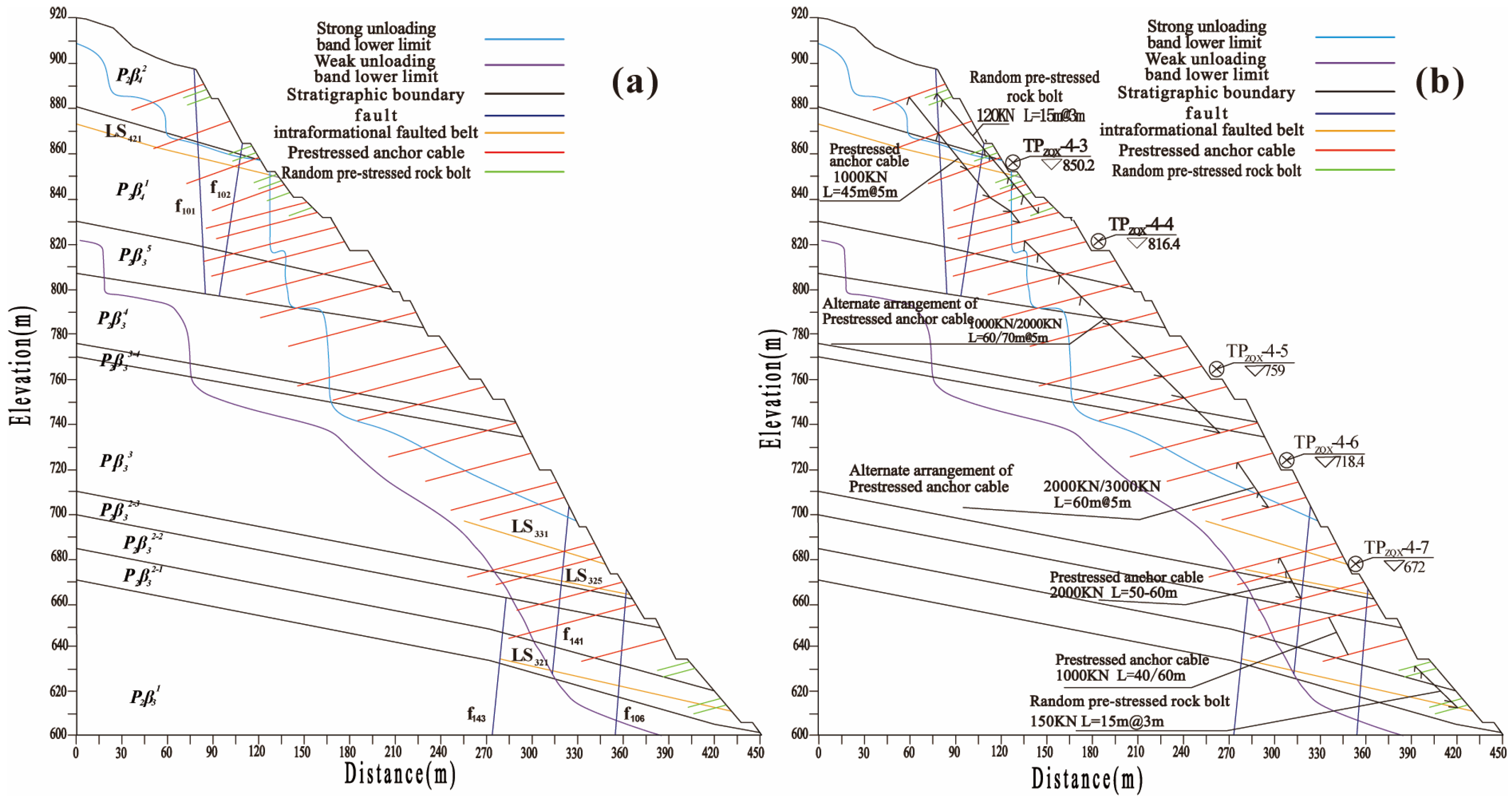
3.1. Engineering Situation

A hydropower project located in the lower reach of the Jinsha River in Southwest China has a design normal reservoir level of 825 m, a dam crest elevation of 834 m, and a concrete double-curvature arch dam with a height of 289 m. The water cushion pond is located behind the dam, with a cross-sectional profile of a flat-bottomed composite trapezoidal shape. The elevation of the pond’s bottom slab is 560 m, its length is 400 m, and the width of the bottom slab is 80 m. The side slopes of the bottom slab are excavated at a 1:1 slope (with a 1:0.6–1:1 slope on the right bank). Two 5 m-wide access roads are set at elevations of 580 m and 601 m. The top elevation of the water cushion pond is 634 m, with a total width of 213.6 m, and a curved waveguide wall is installed at the top. The slopes above the water cushion pond extend from the dam base at 0 m to 900 m. The left bank elevation ranges from 634 m to 950 m, while the right bank elevation ranges from 634 m to over 1100 m.

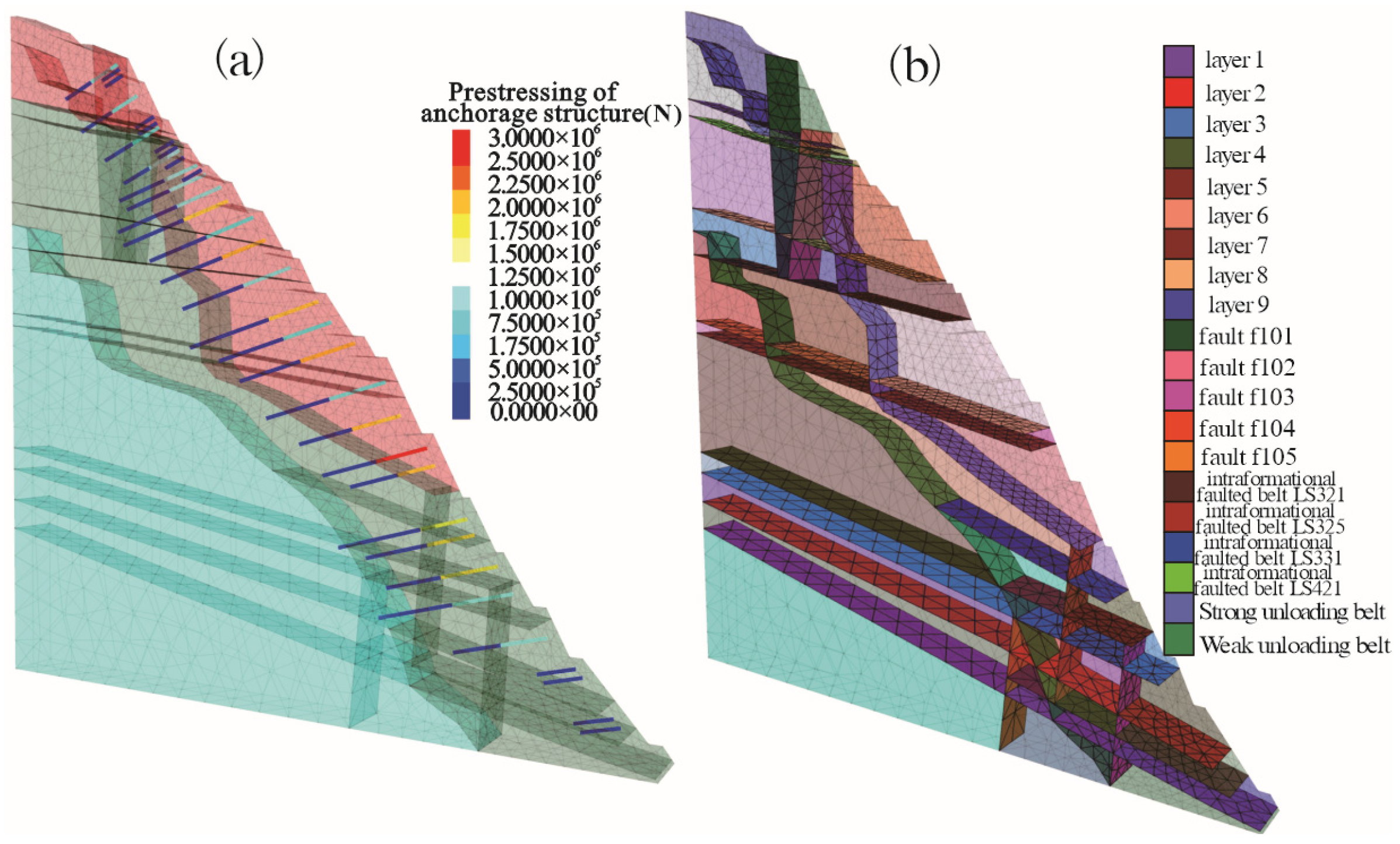
3.2. Characteristics of Rock Slope Anchoring System

Based on the investigation data of the left bank water cushion pond rock mass slope, the rock mass of the slope and above is mainly composed of first-class columnar-jointed basalt, massive basalt, and agglomerate lava. The structural surfaces are well developed within the slope body, the unloading of the rock mass is relatively deep, and the rock mass is primarily classified as type III2 or IV. The dip angle of the gently inclined structural surfaces is smaller than that of the slope, which leads to poor slope stability. Locally, there are blocks formed by NWW-direction faults, near-SN-direction unloading joints, and NNE-direction faults along with gently inclined shear zones. The potential failure mode of the slope stability is block sliding failure along the gently inclined structural surface as the sliding surface. There are two main local failure modes: one is collapse, and the other is block sliding failure. To ensure the long-term stability of the slope, after excavation of the left bank water cushion pond slope, anchor cables are used for reinforcement. The engineering geological slope map and anchor cable layout of the left bank water cushion pond slope are shown in Figure 2.

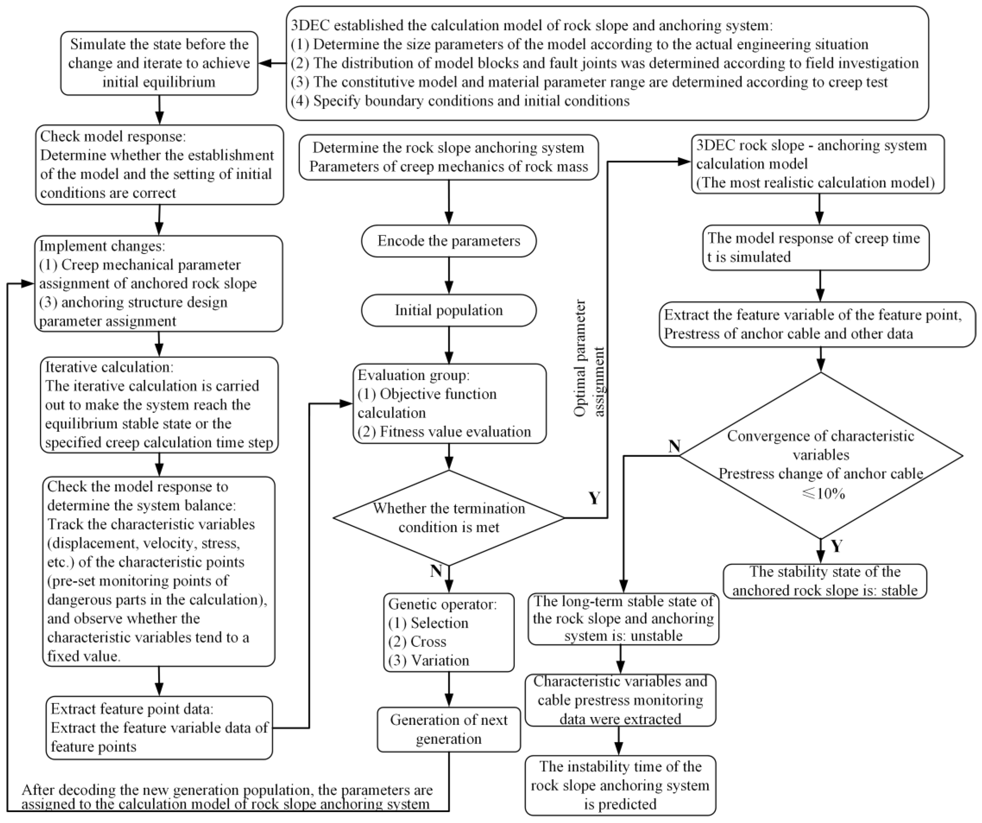
3.3. Stability Evaluation Based on Genetic Algorithm and Discrete Element Analysis

(1)
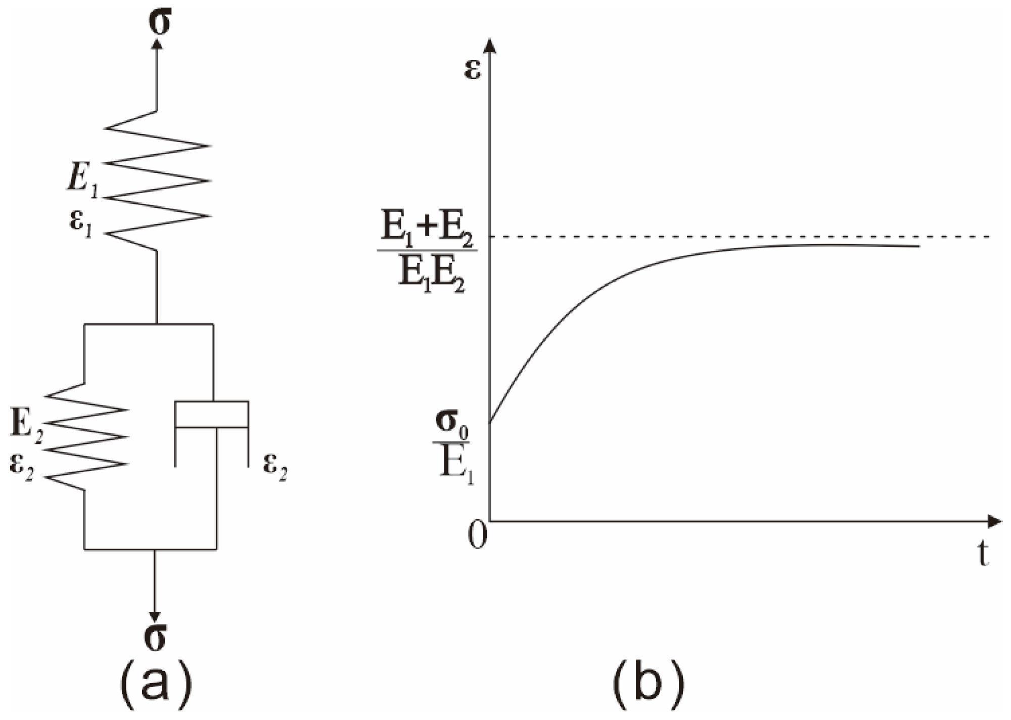
Rock Mass Constitutive Model and Parameter Range
By conducting field-based plate-loading compression creep tests, the constitutive model and parameters of the left bank Shuiwan Rock mass slope were determined. The test applied a constant load to the surface of the rock mass using a flexible hydraulic cushion, measured the creep of the rock mass, and derived the creep equation based on the viscoelastic creep model. This creep equation was used to fit the experimental creep curve, invert the creep model, and optimize the model parameters. The field compression creep test curve indicates that the creep curve of this rock mass material is very similar to the typical creep curve of the generalized Kelvin model. As shown in Figure 3a, the original model of the generalized Kelvin creep model is presented, and Figure 3b illustrates the typical creep curve.
The field test data were subjected to nonlinear fitting, and based on the fitting results, the parameters of the generalized Kelvin model were determined, as shown in Table 2 below.
The parameter values for the generalized Kelvin model, derived from the fitting results, are presented in Table 3.
(2)
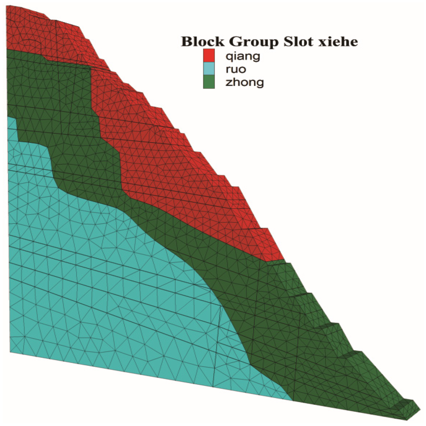
Development of the Numerical Model Using the Discrete Element Method
The numerical computation model is illustrated in Figure 4, Figure 5, Figure 6 and Figure 7.
Based on the project background introduced in the case study, the Hydraulic Prestressed Anchoring Technical Standards (SL/T 212-2020) [44], issued by the Ministry of Water Resources of the People’s Republic of China, are applicable to the design and construction of prestressed anchorage in hydraulic structures. These standards specify the fundamental requirements for anchorage design and construction, including materials and construction equipment, anchor body design, anchorage design, anchor protection, anchorage construction, safety monitoring, anchorage testing, and quality inspection. The parameters for the anchor materials used in the numerical simulation were determined with reference to the relevant provisions in the anchor body design section of the standards, while the mechanical testing parameters were based on the anchorage testing section. Additionally, some parameters were obtained from field measurements and laboratory tests.
The numerical calculation parameters are presented in Table 4, Table 5 and Table 6.
(3)
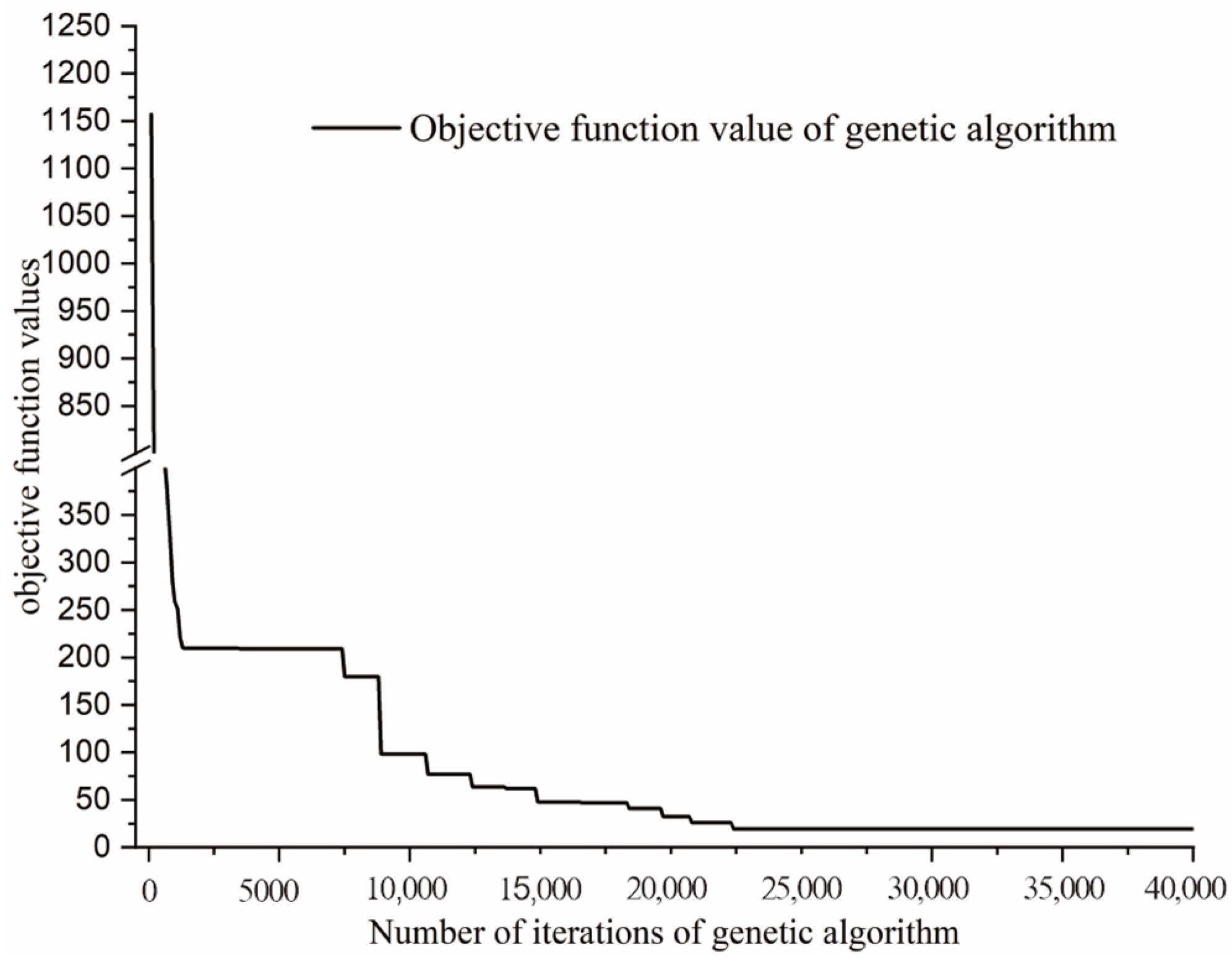
Optimization Using Genetic Algorithm
The genetic algorithm (GA) was implemented to optimize the parameters of the numerical model. The key steps involved in the algorithm are described as follows:
Encoding of Variables
The model parameters to be optimized were encoded into chromosomes using real-number representation, which facilitates precision in continuous parameter optimization. Each chromosome corresponds to a potential solution in the parameter space.
Initialization of Population
An initial population comprising N chromosomes was randomly generated within the defined parameter bounds. This ensured a broad exploration of the search space at the beginning of the evolution process.
Fitness Evaluation
A fitness function was defined based on the discrepancy between the numerical simulation results and field monitoring data (e.g., displacement, stress distribution, or anchor force). The fitness of each individual was evaluated using the objective function. Its mathematical expression is given in Equation (1) below:
f ( x ) = i = 1 n ω i T i m e a s u r e d T i s i m u l a t e d ( x )
where Ti represents a selected monitoring indicator and ωi is its corresponding weight coefficient.
Selection Operator
A roulette wheel selection strategy was employed to probabilistically select individuals for reproduction based on their relative fitness. The higher the fitness value, the greater the probability of being selected. This approach increases the likelihood of high-performing solutions passing their genes to the next generation. The probability of selecting an individual is calculated according to Equation (2):
p i = f ( x i ) j = 1 N f ( x j )
where pi represents the probability of individual i being selected, f(xi) denotes the fitness function value of individual xi, and N represents the population size.
Crossover and Mutation
The selected individuals underwent crossover (e.g., simulated binary crossover) with a predefined probability to generate offspring. Mutation operations (e.g., Gaussian or uniform mutation) were applied to introduce genetic diversity and avoid premature convergence. The implementation is described in Equation (3):
x k = α x i + ( 1 α ) x j , α 0 , 1
where xk denotes the new individual generated through crossover, xi and xj represent the two parent individuals, and α is the crossover factor, which controls the genetic contribution of the parent individuals to the offspring.
Mutation
With a small probability, certain genes of the offspring were mutated to introduce diversity. Mutation can be represented as Equation (4):
x k = x k + δ , δ ~ N ( 0 , σ 2 )
where x k denotes the mutated individual, x k represents the state of the individual before mutation, δ denotes the perturbation following a normal distribution, and σ2 is the variance of the normal distribution.
Replacement
Offspring were evaluated and inserted into the population, replacing less-fit individuals. Elitism was adopted to ensure that the best solution of each generation was preserved in the next generation without modification.
Termination Criteria
The algorithm terminated when either the maximum number of generations was reached or the improvement in fitness fell below a predefined threshold over successive generations. The best-performing chromosome at termination was selected as the optimal parameter set. The termination criterion is given by Equation (5):
max ( f ( x i ) ) max ( f ( x i ) ) p r e v < ε
where max(f(xi)) represents the optimal fitness value in the current population, max(f(xi))prev denotes the optimal fitness value in the previous generation, and ε represents the predefined convergence threshold.
A genetic algorithm was implemented using the Python programming language, leveraging the built-in Python module of 3DEC discrete element analysis software to combine Python with discrete element methods for computational analysis. The 3DEC software provides a dedicated Python module, which enables the implementation of genetic algorithms using the Python programming language. Moreover, this module includes built-in functions that allow direct access to 3DEC numerical simulation commands, covering tasks such as model construction, parameter assignment, boundary condition setup, monitoring of model response data, and exporting of simulation results. By integrating genetic algorithms with these built-in functions, seamless communication between Python and 3DEC can be achieved.
The parameter settings for the genetic algorithm are shown in Table 7 and Table 8 below. The objective function is defined as the sum of the differences between the actual monitored displacements at four monitoring points on the slope, and the displacements are calculated by numerical simulation. When defining the objective function, it is essential to standardize the measurement units. In this engineering case, displacement units for both field monitoring data and numerical simulation results are unified in meters for the formulation of the objective function.
(4)
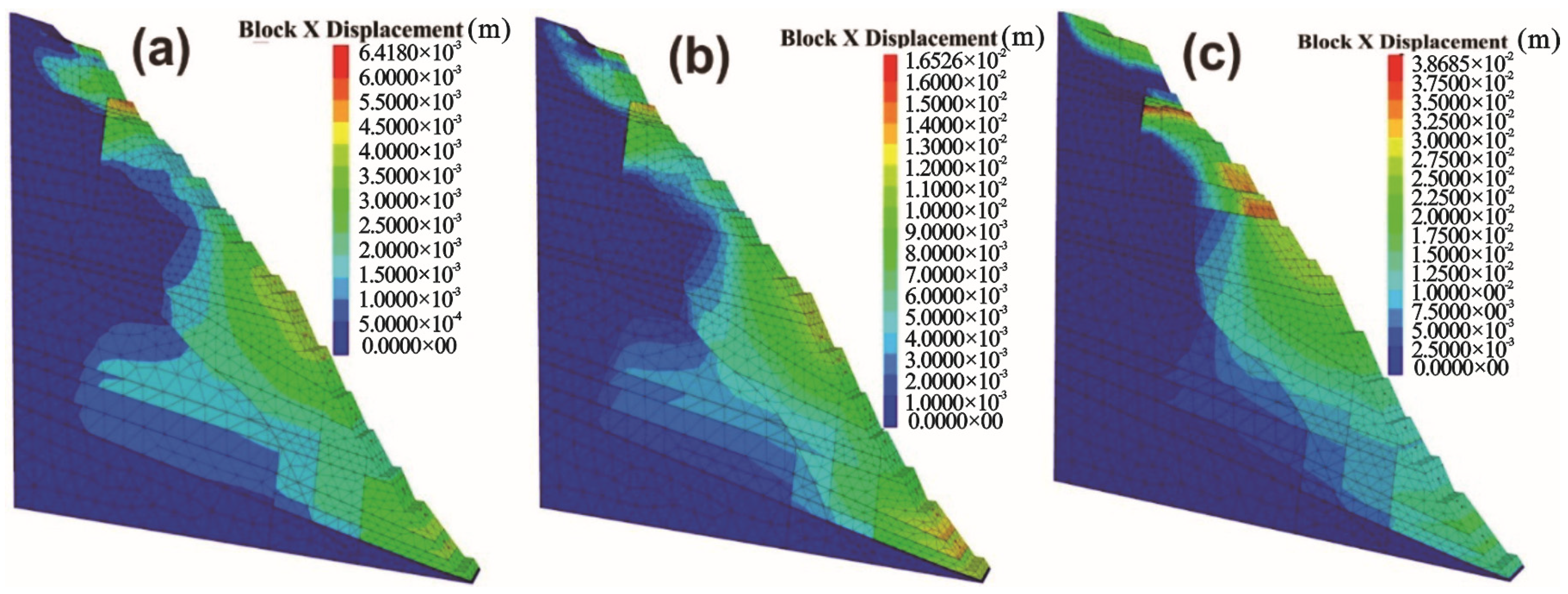
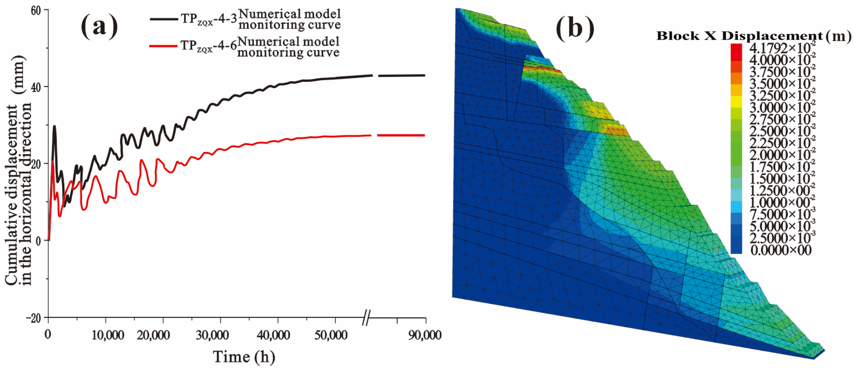
Stability Evaluation of the Left Bank Water Cushion Rock Slope Anchoring System
The computational results based on 3DEC and the discrete element method are shown in Figure 8 below.
The variation of the objective function with the number of iterations is shown in Figure 9 below.
The comparison between the actual displacement curve at the monitoring points and the displacement curve obtained from numerical simulation is shown in Figure 10 below.
The root mean square error (RMSE) was employed to quantitatively analyze the discrepancy between the displacements obtained from the numerical model and those from field monitoring in order to assess the accuracy of the proposed evaluation method. The mathematical expression for RMSE is given in Equation (6):
R M S E = 1 n i = 1 n ( y i y i ) 2
where yi represents the measured (observed) value, yi denotes the corresponding value obtained from the numerical model, and n is the number of samples.
The root mean square error (RMSE) was calculated every 5000 h, and the results for the four monitoring points are shown in the figure below.
As shown in Figure 11, although fluctuations in RMSE were observed during the iterations of the genetic algorithm, an overall decreasing trend is evident. Moreover, the RMSE values at all four monitoring points during the final 5000 h are relatively small. This indicates that the proposed method is both reasonable and effective, significantly improving the accuracy of parameter selection in the discrete element numerical model and providing a solid foundation for subsequent long-term stability evaluations.
In Figure 10, it can be seen that the genetic algorithm objective function converges to a stable, smaller value. At this point, the constitutive parameters obtained through optimization using the genetic algorithm are assigned to the numerical analysis model. The numerical results show a good trend match with the field monitoring results, with small differences. Therefore, it is reasonable to use the generalized Kelvin constitutive model and this set of creep parameters for long-term stability evaluation. The analysis time for the numerical simulation is set to 90,000 h, and the numerical calculation results are shown in Figure 12.
In Figure 12, it can be seen that when the creep time is set to 90,000 h (approximately 10 years), the slope displacement of the anchored rock mass stabilizes, with no significant fluctuations or failures observed. Therefore, it can be concluded that the stability evaluation result of the left bank water cushion rock slope anchoring system is stable. This evaluation result is completely consistent with the trend shown by the actual monitoring data of the rock slope anchoring system, indirectly confirming the rationality of the method.

4. Discussion

In this study, a novel stability evaluation method for rock slope anchorage systems was developed by integrating the discrete element method (DEM) with genetic the algorithm (GA). The proposed approach leverages DEM to obtain comprehensive multi-field data, including displacement fields, stress distributions, and the stress–strain behavior of anchorage structures. Simultaneously, GA is employed to optimize numerical model parameters by fitting them to actual monitoring data, thus ensuring the model accurately reflects in situ conditions. The results demonstrate that this combined methodology is both feasible and reliable, offering a precise representation of the deformation and stress evolution within the rock slope anchorage system. Moreover, the method provides a clear visualization of the system’s stability evolution, allowing for an intuitive and dynamic evaluation of slope stability. The effectiveness of the proposed method arises from the complementary strengths of DEM and GA. DEM is well-suited for modeling large displacements, contact surface sliding, and separation in discontinuous rock masses, capturing the internal deformation and stress redistribution across structural planes and jointed rock masses with high fidelity. Meanwhile, GA contributes robust global optimization capabilities, with strong adaptability and resilience, enabling efficient calibration of model parameters. Compared to traditional rigid limit equilibrium methods, which fail to account for the interactive behavior between the rock slope and anchorage system or the progressive evolution of stability, this approach offers a more integrated and dynamic assessment framework. Additionally, by incorporating actual monitoring data into the optimization process, the method addresses the limitations of conventional DEM analyses that often rely solely on laboratory-derived parameters, which may not accurately represent field conditions.
However, certain limitations remain. The method is highly dependent on the quality and availability of monitoring data, which directly influences the accuracy of model calibration and, consequently, the reliability of stability evaluations. In future research, we aim to enhance the robustness of the approach by integrating multi-dimensional monitoring datasets into the objective function. This will allow cross-validation among different data sources, thereby mitigating the impact of low-quality measurements and improving the precision of GA-based parameter optimization. Currently, the stability assessment focuses primarily on horizontal displacement, as it serves as a sensitive and critical indicator of the overall stability state of the rock slope anchorage system. Horizontal displacement tends to exhibit pronounced changes during instability events. Nonetheless, considering displacement in three dimensions—including vertical and lateral movements—would provide a more comprehensive understanding of system behavior. However, such an extension would significantly increase computational demands, making it less practical for real-time engineering applications given the limitations of current optimization and DEM computation speeds. Future developments will focus on algorithmic improvements, including parallel computing strategies, to enable efficient multi-dimensional analysis for more holistic stability assessments. Additionally, the study employs the Kelvin model, which represents linear viscoelastic behavior through a parallel configuration of ideal springs and dashpots. While suitable for describing steady-state creep in rock slopes, the Kelvin model is inadequate for capturing non-linear damage accumulation associated with brittle failure or accelerated creep phenomena. It lacks failure criteria related to stress concentration or tensile limits and does not account for microstructural defect evolution, such as grain boundary sliding or void formation, which are critical during rapid deformation processes. Consequently, the current method is best suited for slopes composed of rocks exhibiting steady-state creep, and its applicability to brittle rock or rapid failure scenarios is limited. To address this, future research will explore the incorporation of advanced constitutive models and machine learning techniques, including neural networks, ensemble algorithms, and random forest, to enable automated identification of appropriate constitutive models and optimization of their parameters, thereby broadening the method’s applicability across diverse geological settings.

5. Conclusions

(1)
The stability evaluation method for the rock slope anchoring system proposed in this paper considers the interaction between the anchoring structure and the rock slope and accurately reflects the displacement, deformation, and stress distribution of the rock mass slope anchoring system.
(2)
The stability evaluation method for the rock slope anchoring system is based on the discrete element method, which can fully account for large displacements in discontinuous rock masses and phenomena such as contact surface slip and separation and can more accurately reflect the internal deformation and stress distribution of structural surfaces and jointed rock masses. Simultaneously, a genetic algorithm is introduced to optimize the parameters of the numerical model, effectively improving the evaluation efficiency. Furthermore, the most representative numerical analysis model for the engineering conditions is obtained, combining the practical engineering situation with the numerical model, thereby improving the accuracy of the stability evaluation.
(3)
This evaluation method clearly presents the stability evolution process of the rock slope anchoring system, providing intuitive evaluation results.

Author Contributions

P.X.: Conceptualization, Funding acquisition, Methodology, Project administration, Writing—original draft, Writing—review and editing, Supervision, Resources. B.Z.: Formal analysis, Data curation, Investigation, Software, Visualization, Writing—original draft. Y.P.: Formal analysis, Data curation, Resources, Validation, Writing—review and editing. All authors have read and agreed to the published version of the manuscript.

Funding

This research was funded by The National Natural Science Foundation of China grant number 42407225, Fujian Provincial Education Department Foundation grant number JAT231047, Xiamen Science and Technology Subsidy Project grant number 2024CXY0319, Research Start-up Fundation of Jimei University grant number ZQ2023019 and the APC was funded by the National Natural Science Foundation of China (No. 42407225).

Institutional Review Board Statement

Not applicable.

Informed Consent Statement

Not applicable.

Data Availability Statement

The datasets generated during and/or analyzed during the current study are available from the corresponding author upon reasonable request.

Acknowledgments

The authors would like to extend sincere gratitude to Xiaofeng Ye from the Xinjiang Uygur Autonomous Regional Bureau of Geology’s Center for Geophysical and Geochemical Exploration for his dedicated efforts in experimental data collection, processing, and formal analysis of the manuscript. His meticulous work substantially enhanced the technical validity of this study. We also acknowledge Feng Yan of Xinjiang Science and Industry Geological Exploration Co., Ltd. for providing critical experimental materials and performing rigorous validation of research outcomes, which ensured the reproducibility of our conclusions. Their domain-specific expertise and collaborative engagement were pivotal to the successful completion of this project.

Conflicts of Interest

Author Peng Xia was employed by the company “Xinjiang Transportation Science Research Institute Co., Ltd., Urumqi”. The remaining authors declare that the research was conducted in the absence of any commercial or financial relationships that could be construed as a potential conflict of interest.

References

  1. He, M.; Ren, S.; Guo, L.; Lin, W.; Zhang, T.; Tao, Z. Experimental study on influence of host rock strength on shear performance of Micro-NPR steel bolted rock joints. Int. J. Rock Mech. Min. Sci. 2022, 159, 105236. [Google Scholar] [CrossRef]
  2. Li, C.C. Field observations of rock bolts in high stress rock masses. Rock Mech. Rock Eng. 2010, 43, 491–496. [Google Scholar] [CrossRef]
  3. Ma, S.; Zhao, Z.; Shang, J. An analytical model for shear behaviour of bolted rock joints. Int. J. Rock Mech. Min. Sci. 2019, 121, 104019. [Google Scholar] [CrossRef]
  4. Pei, S.F.; Hao, W.F.; Fan, Y.L.; Chen, H.; Li, W.T. Operation condition of anchoring system in large-scale water conservancy and hydropower projects. J. Chang. Jiang River Sci. Res. Institute 2024, 41, 142–150. (In Chinese) [Google Scholar]
  5. Wen, L.; Huang, L.; Xiang, X.; Yang, X.Z.; Zhang, G.C. Research status and development trend of geotechnical anchorage technology in hydropower projects. Saf. Environ. Eng. 2023, 30, 35–45. (In Chinese) [Google Scholar]
  6. Deng, D.P.; Li, L.; Zhao, L.H. Stability analysis of slopes reinforced with anchor cables and optimal design of anchor cable parameters. Eur. J. Environ. Civ. Eng. 2021, 25, 2425–2440. [Google Scholar] [CrossRef]
  7. Bian, X.; Liu, J.; Nie, L.; Ma, S.; Tao, W.; Qiu, C.; Xu, G. Reliability evaluation of a high slope reinforced by anchor based on the stochastic finite-element method: Case study. Case Stud. Constr. Mater. 2023, 19, e02650. [Google Scholar] [CrossRef]
  8. Chen, J.F.; Du, C.C.; Peng, M.; Sun, R.; Zhao, F.; Shi, Z.M. System reliability analysis of a slope stabilized with anchor cables and piles under seismic loading. Acta Geotech. 2023, 18, 4493–4514. [Google Scholar] [CrossRef]
  9. Park, H.; West, T.R. Development of a probabilistic approach for rock wedge failure. Eng. Geol. 2001, 59, 233–251. [Google Scholar] [CrossRef]
  10. Ahmadabadi, M.; Poisel, R. Probabilistic analysis of rock slopes involving correlated non-normal variables using point estimate methods. Rock Mech. Rock Eng. 2016, 49, 909–925. [Google Scholar] [CrossRef]
  11. Duzgun, H.S.B.; Bhasin, R.K. Probabilistic stability evaluation of Oppstadhornet rock slope, Norway. Rock Mech. Rock Eng. 2009, 42, 729–749. [Google Scholar] [CrossRef]
  12. Li, N.; Li, G.; He, M. Key techniques for the analysis and evaluation of high rock slopes. Arab. J. Geosci. 2021, 14, 1171. [Google Scholar] [CrossRef]
  13. Chen, S.; Yang, Z.; Zhang, W.; Li, L.; Zheng, Y.; Yuan, Y. Numerical simulation of the stability of a cutting slope and study on its reinforcement scheme. Adv. Civ. Eng. 2022, 2022, 5306923. [Google Scholar] [CrossRef]
  14. Liu, Y.; Lai, J.; Xu, J. Study on slope monitoring and stability based on bolt–cable combined support. Buildings 2024, 14, 886. [Google Scholar] [CrossRef]
  15. Bi, J.; Luo, X.; Zhang, H.; Shen, H. Stability analysis of complex rock slopes reinforced with prestressed anchor cables and anti-shear cavities. Bull. Eng. Geol. Environ. 2019, 78, 2027–2039. [Google Scholar] [CrossRef]
  16. Yan, M.; Xia, Y.; Liu, T.; Bowa, V.M. Limit analysis under seismic conditions of a slope reinforced with prestressed anchor cables. Comput. Geotech. 2019, 108, 226–233. [Google Scholar] [CrossRef]
  17. Sun, J.; Yu, T.; Dong, P. Pseudo-dynamic analysis of reinforced slope with anchor cables. Soil Dyn. Earthq. Eng. 2022, 162, 10751. [Google Scholar] [CrossRef]
  18. Hara, T.; Tatta, N.; Yashima, A. Assessment of ground-anchored slope stability based on variation in residual tensile forces. Soils Found. 2023, 63, 101353. [Google Scholar] [CrossRef]
  19. Jiang, L.; Zhang, Q.; Jia, C.; Yu, J.; Huang, Q. Investigating on deformation characteristics and failure mechanism of bedding rock slope: Field study, long-term monitoring, and reinforcement measures. Environ. Earth Sci. 2024, 83, 45. [Google Scholar] [CrossRef]
  20. Lin, C.; Li, T.; Zhao, L.; Zhang, Z.; Lin, C.; Liu, X.; Niu, Z. Reinforcement effects and safety monitoring index for high steep slopes: A case study in China. Eng. Geol. 2020, 279, 105861. [Google Scholar] [CrossRef]
  21. Tao, Z.; Wang, Y.; Zhu, C.; Xu, H.; Li, G.; He, M. Mechanical evolution of constant resistance and large deformation anchor cables and their application in landslide monitoring. Bull. Eng. Geol. Environ. 2019, 78, 4787–4803. [Google Scholar] [CrossRef]
  22. Sun, L.; Grasselli, G.; Liu, Q.; Tang, X.; Abdelaziz, A. The role of discontinuities in rock slope stability: Insights from a combined finite-discrete element simulation. Comput. Geotech. 2022, 147, 104788. [Google Scholar] [CrossRef]
  23. Tao, Z.; Zhang, T.; Zhu, D.; Gong, W.; He, M. Physical modeling test on deformation and failure of rock slope with new support system. Adv. Civ. Eng. 2020, 2020, 8825220. [Google Scholar] [CrossRef]
  24. Liu, S.Y.; Shao, L.T.; Li, H.J. Slope stability analysis using the limit equilibrium method and two finite element methods. Comput. Geotech. 2015, 63, 291–298. [Google Scholar] [CrossRef]
  25. Griffiths, D.V.; Fenton, G.A. Probabilistic slope stability analysis by finite elements. J. Geotech. Geoenviron. Eng. 2004, 130, 507–518. [Google Scholar] [CrossRef]
  26. Bao, Y.; Li, Y.; Zhang, Y.; Yan, J.; Zhou, X.; Zhang, X. Investigation of the role of crown crack in cohesive soil slope and its effect on slope stability based on the extended finite element method. Nat. Hazards 2022, 110, 295–314. [Google Scholar] [CrossRef]
  27. Jing, L. A review of techniques, advances and outstanding issues in numerical modelling for rock mechanics and rock engineering. Int. J. Rock Mech. Min. Sci. 2003, 40, 283–353. [Google Scholar] [CrossRef]
  28. Nguyen, P.M.V.; Marciniak, M. Stochastic rock slope stability analysis: Open pit case study with adjacent block caving. Geotech. Geol. Eng. 2024, 42, 5827–5845. [Google Scholar] [CrossRef]
  29. Yang, H.; Zhang, L. Bayesian back analysis of unsaturated hydraulic parameters for rainfall-induced slope failure: A review. Earth-Sci. Rev. 2024, 251, 104714. [Google Scholar] [CrossRef]
  30. Li, T.; Liu, G.; Wang, C.; Wang, X.; Li, Y. The probability and sensitivity analysis of slope stability under seepage based on reliability theory. Geotech. Geol. Eng. 2020, 38, 3469–3479. [Google Scholar] [CrossRef]
  31. Kumar, A.; Pandit, B.; Tiwari, G. Reliability-based stability analysis of large rock slopes with different failure mechanisms using response surface methodology. Environ. Earth Sci. 2022, 81, 511. [Google Scholar] [CrossRef]
  32. Yu, J.; Zhang, Q.; Wu, C.; Jia, C. Investigation on stability of soil–rock mixture slope with discrete element method. Environ. Earth Sci. 2023, 82, 449. [Google Scholar] [CrossRef]
  33. Lu, Y.; Tan, Y.; Li, X. Stability analyses on slopes of clay-rock mixtures using discrete element method. Eng. Geol. 2018, 244, 116–124. [Google Scholar] [CrossRef]
  34. An, H.; Fan, Y.; Liu, H.; Cheng, Y.; Song, Y. The state of the art and new insight into combined finite–discrete element modelling of the entire rock slope failure process. Sustainability 2022, 14, 4896. [Google Scholar] [CrossRef]
  35. Holland, J.H. Adaptation in natural and artificial systems. Q. Rev. Biol. 1975, 6, 126–137. [Google Scholar]
  36. Goldberg, D.E.; Holland, J.H. Genetic algorithms and machine learning. Mach. Learn. 1988, 3, 95–99. [Google Scholar] [CrossRef]
  37. Fatty, A.; Li, A.J.; Qian, Z.G. An interpretable evolutionary extreme gradient boosting algorithm for rock slope stability assessment. Multimed. Tools Appl. 2024, 83, 46851–46874. [Google Scholar] [CrossRef]
  38. Katoch, S.; Chauhan, S.S.; Kumar, V. A review on genetic algorithm: Past, present, and future. Multimed. Tools Appl. 2021, 80, 8091–8126. [Google Scholar] [CrossRef]
  39. Soumaya, Z.; Taoufiq, B.D.; Benayad, N.; Yunus, K.; Abdelkrim, A. The detection of Parkinson disease using the genetic algorithm and SVM classifier. Appl. Acoust. 2021, 171, 107528. [Google Scholar] [CrossRef]
  40. Zheng, Y.; Chen, C.; Meng, F.; Liu, T.; Xia, K. Assessing the stability of rock slopes with respect to flexural toppling failure using a limit equilibrium model and genetic algorithm. Comput. Geotech. 2020, 124, 103619. [Google Scholar] [CrossRef]
  41. Zheng, Y.; Chen, C.; Meng, F.; Zhang, H.; Xia, K.; Chen, X. Assessing the stability of rock slopes with respect to block-flexure toppling failure using a force-transfer model and genetic algorithm. Rock Mech. Rock Eng. 2020, 53, 3433–3445. [Google Scholar] [CrossRef]
  42. Xu, J.; Du, X. Seismic stability of 3D rock slopes based on a multi-cone failure mechanism. Rock Mech. Rock Eng. 2023, 56, 1595–1605. [Google Scholar] [CrossRef]
  43. He, B.; Du, X.; Bai, M.; Yang, J.; Ma, D. Inverse analysis of geotechnical parameters using an improved version of non-dominated sorting genetic algorithm II. Comput. Geotech. 2024, 171, 106416. [Google Scholar] [CrossRef]
  44. SL/T 212-2020; Technical Specification for Hydraulic Prestressed Anchorage. China Water & Power Press: Beijing, China, 2020.
Figure 1. Flowchart of GA-DEM-based stability evaluation for rock slope anchoring systems.
Applsci 15 05057 g001
Figure 2. Cross-sectional Diagram of the Left Bank Water Cushion Pond Slope. (a) Engineering Geological Profile (b) Layout of Anchor Cables (Rods) and Monitoring Setup for Slope Surface Displacement.
Applsci 15 05057 g002
Figure 3. Generalized Kelvin element model and typical creep curve. (a) Generalized Kelvin element model; (b) typical relationship between deformation and time for the generalized Kelvin constitutive model.
Applsci 15 05057 g003
Figure 4. Numerical computation model.
Applsci 15 05057 g004
Figure 5. Stratigraphic distribution in the numerical model.
Applsci 15 05057 g005
Figure 6. Distribution of unloading zones in the numerical model.
Applsci 15 05057 g006
Figure 7. Layout of anchor cables and distribution of structural surfaces. (a) Anchor cable layout diagram of the rock slope anchorage system; (b) distribution of structural planes in the rock slope anchorage system.
Applsci 15 05057 g007
Figure 8. Numerical simulation results. (a) Cumulative horizontal displacement curve with a creep time of 2000 h; (b) cumulative horizontal displacement curve with a creep time of 10,000 h; (c) cumulative horizontal displacement curve with a creep time of 45,000 h.
Applsci 15 05057 g008
Figure 9. Variation of the objective function with iteration count.
Applsci 15 05057 g009
Figure 10. Comparison between the numerical simulation monitoring curve and actual displacement monitoring curve. (a) Cumulative horizontal displacement monitoring curve at monitoring point TPZQX4-3; (b) cumulative horizontal displacement monitoring curve at monitoring point TPZQX4-4; (c) cumulative horizontal displacement monitoring curve at monitoring point TPZQX4-5; (d) cumulative horizontal displacement monitoring curve at monitoring point TPZQX4-6.
Applsci 15 05057 g010
Figure 11. The RMSE between the displacements from the numerical model and the actual monitored displacements. (a) RMES at monitoring point TPZQX4-3; (b) RMES at monitoring point TPZQX4-4; (c) RMES at monitoring point TPZQX4-5; (d) RMES at monitoring point TPZQX4-6.
Applsci 15 05057 g011
Figure 12. Numerical simulation results for creep time of 90,000 hours. (a) Slope displacement monitoring curves for TPZQX-4-3 and TPZQX-4-; (b) horizontal displacement contour map.
Applsci 15 05057 g012
Table 1. Summary of stability evaluation methods for rock slope anchorage systems.
Evaluation Method of Rock Slope Anchorage Systems StabilityResearch ContentReference
Reliability TheoryApplied reliability theory to calculate the probability of rock slope failure and assessed the stability of high slopes reinforced with anchorage.Bian [7]
Proposed a stability evaluation method for anchored slopes based on system reliability analysis (SRA), considering the effects of local failures in anchors and piles on overall system performance.Chen [8]
Demonstrated the accuracy and effectiveness of PEMS, FORM, SORM, and MCS in addressing various reliability issues in rock slope stability assessment.Park [9]
Ahmadabadi [10]
Duzgun [11]
Finite Element AnalysisDeveloped a frictional contact interface element for potential sliding surfaces and proposed a novel numerical model for prestressed anchors to compute the slope stability factor using a direct finite element method.Li [12]
Utilized the strength reduction method (SRM) in conjunction with finite element software to analyze the stability of slopes under reinforcement conditions.Chen [13]
Employed FLAC 3D numerical simulation software to evaluate the reliability of support design and slope stability based on variations in shear strain and displacement.Liu [14]
Analytical MethodApplied an improved limit equilibrium method to assess the stability of anchored slopes.Bi [15]
Deng [16]
Combined limit analysis, the principle of minimum potential energy, and the pseudo-dynamic method to propose a seismic stability evaluation approach that accounts for dynamic variations in anchor axial forces.Yan [16]
Sun [17]
Monitoring and DetectionProposed a comprehensive stability assessment method for anchored slopes based on residual tension variations, validated through pull-out testing.Hara [18]
Conducted continuous deformation monitoring of slopes after reinforcement and analyzed the data to evaluate the stability of a layered rock slope with anchorage.Jiang [19], Lin [20]
Developed a remote monitoring and forecasting system for landslides using constant resistance to large deformation (CRLD) anchors, aimed at predicting the stability of rock slope anchoring systems.Tao [21]
Analyzed slope stability by monitoring structural force variations in anchor rods and cables during and after excavation processes.Liu [14]
Model TestingConducted laboratory physical model experiments on collapse control and monitoring, investigating failure characteristics and the effectiveness of energy-absorbing reinforcement measures.Tao [23]
Table 2. Summary of fitted parameters for the generalized Kelvin model.
Test Point NoPressure (MPa)Generalized Kelvin Model Parameters
E1 (GPa)E2 (GPa)H (GPa·h)r2
C36-10111.231398138095%
C36-10212.0618173895196%
C36-10311.3875655094.2%
C36-20111.381579500096.2%
C36-20212.061094384090%
C36-20312.14849690097.4%
Table 3. Table of parameter ranges for rock mass creep.
E1E2η
7 GPa~18 GPa49 GPa~173 GPa550 GPa·h ~8951 GPa·h
Table 4. Parameter values for anchor cables.
Cross-sectional Area (mm2)140
Elastic Modulus (GPa)190
Strength Grade (MPa)1860
Ultimate Load of Anchor Cable (kN)265
Strain Limit of Anchor Cable0.035
Grout Strength (MPa)30
Table 5. Summary table of rock mass parameter values.
LithologyRock Mass CategoryLithological LayerWeathering and Unloading StateDeformation Modulus
(GPa)
Poisson’s
Ratio
Density
(kN/m3)
Shear Strength Parameters
fc
(MPa)
BasaltIV1P2β2~P2β6slight weathering, strong unloading.30.3225.80.550.40
III2columnar-jointed basalt, agglomerate lavaslight weathering, slight unloading.70.2727.30.900.75
P2β2~P2β6 (excluding columnar-jointed basalt and agglomerate lava)slight weathering, slight unloading
III1columnar-jointed basalt, agglomerate lavaslightly fresh,
no unloading
90.2427.21.11.1
P2β2~P2β6 (excluding columnar-jointed basalt and agglomerate lava)slight weathering, slight unloading
II2β2~P2β6 (excluding columnar-jointed basalt and agglomerate lava)slightly fresh,
no unloading
170.2228.71.31.4
Table 6. Summary Table of Shear Zone and Fault Parameter Values.
TypeIdentification NumberDeformation Modulus
(GPa)
Shear Strength Parameters
fc (MPa)
Shear ZoneLS3213.750.400.06
LS3313.850.380.07
LS3253.80.380.06
LS4214.140.450.07
Faultf1012.450.430.08
f1022.460.430.08
f1433.650.350.05
f1413.640.350.05
f1064.350.350.05
Table 7. Genetic algorithm parameters.
Objective FunctionObjective DimensionPopulation SizeMaximum Number of IterationsMutation Probability
Difference between the numerical model slope monitoring data and actual monitoring data3301000.01
Table 8. Range of numerical model parameters and optimization precision.
Upper Limit of Creep ParametersLower Limit of Creep ParametersPrecision
7180.1
491731
55089511
Disclaimer/Publisher’s Note: The statements, opinions and data contained in all publications are solely those of the individual author(s) and contributor(s) and not of MDPI and/or the editor(s). MDPI and/or the editor(s) disclaim responsibility for any injury to people or property resulting from any ideas, methods, instructions or products referred to in the content.

