Article

Reducing Railway Track Vibrations by Applying Particle-Damping Systems

by
Felipe Klein Fiorentin
1,*,
Cristian Piehowiak
1,
Anelize Zomkowski Salvi
1,
Yesid Ernesto Asaff
1,
Andrea Piga Carboni
1,
Abílio Manuel Pinho de Jesus
2,3 and
Thiago Antonio Fiorentin
1
1
Department of Mobility Engineering, UFSC (Federal University of Santa Catarina), Joinville 89219-600, Brazil
2
Institute of Science and Innovation in Mechanical and Industrial Engineering—INEGI, 4200-465 Porto, Portugal
3
Faculty of Engineering, University of Porto, 4200-465 Porto, Portugal
*
Author to whom correspondence should be addressed.
Appl. Sci. 2025, 15(9), 5014; https://doi.org/10.3390/app15095014
Submission received: 28 February 2025 / Revised: 26 March 2025 / Accepted: 3 April 2025 / Published: 30 April 2025

Abstract

:

Featured Application

The present work focuses on the mechanical characterization of particle damper systems designed to reduce railway vibrations, reducing the negative impact of rail transit due to noise and vibrations.

Abstract

The wheel–rail contact is an intrinsic characteristic of rail transport. This contact is one of the main reasons why rails are so efficient for transportation, mainly due to the very low friction coefficient between them and the wheels. However, this strong argument also leads to a disadvantage: the wheel contact is also associated with excessive vibration and noise, which have a strong impact on the passengers’ comfort and especially the surrounding community. These noises and vibrations impact the public in several ways, like disturbing sleep, increasing stress and heart-associated diseases. The main objective of the present work is to investigate the rail vibration attenuation by applying particle dampers. Four different particles will be studied, and their effectiveness in reducing the rail vibrations will be analysed. Promising results were found, where under certain conditions, the particle dampers, such as lead and magnetite particles, were able to reduce peak vibration levels by more than an order of magnitude. The application of this system may have a strong impact on the communities using and in the vicinity of rail systems by reducing the noise and vibration, consequently improving people’s health and well-being.

1. Introduction

Noise and vibration have a severe impact on people’s health and well-being, and this influence has greatly increased in recent years, mainly due to the significant increase in traffic over the years from several different modal transportation systems, like trains, cars, and planes. Wrótny et al. [1] performed extensive research regarding the impact of road and rail noise on people’s lives and found that traffic has amplified severe health issues, like sleep disturbances and noise annoyance.
Although trains are well known for being very efficient and eco-friendly (when compared to other modal transportation systems), they also have a negative impact on people’s health, mainly due to excessive noise and vibration levels. Regarding this topic, several interviews were conducted by Maclachlan et al. [2] about the perception of vibrations generated by rails in nearby communities. They have observed that there is a general feeling about the increase in traffic, speed, and noise. Moreover, several individuals have reported great concern regarding vibrations, with some experiencing glasses shaking in display cabinets, wall pictures moving out of place, and cracks appearing and growing in the walls. Regarding symptoms, people reported increases in stress levels, irritation, tiredness in the morning and difficulty sleeping.
Smith et al. [3] developed an interesting work investigating the effect of freight train traffic on people’s health, especially regarding sleep. They have found that vibration levels have several different impacts, such as poor sleep, awakenings overnight, difficulty falling asleep, and tiredness. Another work focusing on train impacts on people’s quality of sleep was developed by Croy et al. [4]. They have monitored the heart rates of individuals during sleep and have found that the vibration generated by the train had a significant impact on increasing heart rates. Moreover, they have observed that these variations remained even after dozens of seconds. Such variations reduce the rest effectiveness during sleep, increasing stress levels and other negative impacts on human health.
Some authors found strong relations between a lack of proper maintenance and the noise emitted by the trains [5]. They have measured the roughness for several train lines and found that several of them were outside the standard limits. Another work concerning wear and its impact on the noise was conducted by Höjer et al. [6]. They have developed a real-time monitoring system for rail conditions. Once more, a stronger correlation between noise levels and track wear was observed, where very high noise levels were measured in severely worn track sections. Within the noise generated by train topics, Zhang et al. [7] quantified the contribution of each train part to the total noise generated by a train. They have found that the bogie and other lower-region parts were one of the main contributors.
Regarding vibrations generated by train and their impact, a wide-ranging review study was conducted by Connolly et al. [8]. Some authors were able to successfully correlate vibration amplitude with annoyance levels in people in the vicinity of railroads [9].
They have observed that complaining reports regarding noise and vibration in areas close to railroads increased drastically over the last years. Moreover, it was found that when vibrations were measured, in more than 40% of the cases, vibration levels exceeded the national or international allowable limits. They have observed that in approximately 1/3 of the studied cases, the threshold for ground-borne noise from freight trains was exceeded, although more data are required to draw more conclusive statements. Another work focusing on the impacts of vibration generated by trains was developed by Sanayei et al. [10]. Since isolating structures that are already built from these vibrations is often too expensive, understanding and controlling these vibration levels is essential. They have measured vibrations in buildings located near surface trains and subways and found that the trains excited the surrounding buildings at certain frequencies; human comfort is strongly compromised, and this issue could be addressed in the project of new buildings. Regarding the same topic, Zou et al. [11] have studied the effect of these vibrations in tall buildings, and have observed that vibrations were amplified in certain cases, depending on which floor the measurements were performed, and could surpass the comfort levels determined by some standards and associations, like the FTA (Federal Transit Administration, Washington, DC, USA) [12].
For freight trains, when considering fuel efficiency, typical optimal speeds are around 50 km/h [13]; however, optimal values may vary according to the engine type, load, terrain, railway type, and other factors. In this speed range, the noise (and vibration levels) is dominated by the rolling phenomenon (wheel–steel rail system) [14]. While for lower speeds, the total noise’s main component is associated with the traction noises [15], the train’s aerodynamics dominates the noise generation at high speeds [16] (above approximately 250 km/h). Consequently, if the main objective is to reduce noise and vibration for freight trains (or other types of trains with similar average speeds), focusing on the wheel and the train track is essential. For the present work, the attenuation of the steel rail vibrations will be the main target. The vibration generated by freight trains is linked with several health conditions associated with sleep disturbance [17].
Part of the traditional railroad building components, like wooden sleepers and ballast, helps with vibration attenuation; however, they are often not enough. Passive dampers are solutions used to reduce the vibration levels. They are known to be simple and robust [18]. They are constructed using mechanical devices, and they are designed to dissipate a fraction of the system’s kinetic energy [19]. Typical passive dampers are built using viscoelastic materials, tuned mass dampers (TMD), and moving particles (particle dampers) [20].
Tuned dampers were studied for applications in steel rails, like in the work proposed by Jin et al. [21], where by using a tuned mass inside a viscoelastic material, they observed increases in damping performance of up to five times (when measuring the damping coefficient). Another application for TMD, focusing on high-speed railway bridges, was developed by Lin et al. [22]. By designing and applying a group of tuned mass dampers, the authors were able to reduce the maximum acceleration of the bridge structure by as much as 50%. The authors have observed that better performance was achieved when the vibration was dominated by the structure’s natural frequencies (resonance) and the train excited those frequencies (for example, by running at specific speeds that led to these excitation frequencies).
Concerning particle dampers, the working principle can be summarised as transferring kinetic energy from the structure to the particles; afterwards, part of this energy is dissipated due to collisions and friction within the particles and between the particles and the structure (or the recipient wall) [23]. Some key parameters strongly affect the efficiency of particle dampers, namely: particle size, packing ratio, position, particle overlap and excitation frequency, amplitude and orientation, for example [24]. Depending on these characteristics, the particle motion can be characterised as follows: fluid-like movement, where particles act like a liquid; collect-and-collide, where particles move similarly to a single block, colliding with the reservoir walls; and decoupled, where particles’ movement displays a high level of independence from one another [25].
A very comprehensive study was performed by Xu et al. [26] regarding particle size and their damping efficiency. They have found a relation between the diameter of a specific particle material and its efficiency for a certain frequency, where larger (or heavier) particles tend to be more efficient for higher frequencies. This observation is very important in terms of designing a damper, as it can act as an initial guide for choosing the most suitable particles for reducing vibrations under certain loading conditions.
Some works studied the efficiency of particle dampers in reducing vibration for several different applications, like a wind turbine stator [27], circuit boards [28], cutting tools [29], turbines [30], and engines [31], yielding promising results. One more interesting application of particle dampers was developed by Xin [32]. In this work, deep learning methodology was applied to particle dampers for noise and vibration control of steel rails. Several materials and particle sizes were studied, and their damping efficiency was analysed. They were able to significantly reduce track vibrations in most test conditions, except for impact vibrations caused by the passing wheels.
Regarding the railway, different vibration control analyses can be applied, focusing on the control of the vehicles themselves [33] or the infrastructure [34]. An interesting study was developed by Jin et al. [35], in which a tuned particle impact (single particle confined in a reservoir) was used to minimise vibration and noise at a rail track; the vibration amplitudes and sound pressure levels were reduced by approximately half. Regarding the applications of particle dampers in rails, a comprehensive study was conducted by Lu et al. [36], where several excitation frequencies and amplitudes were studied for a certain reservoir and particles (these parameters were not changed). Solutions regarding particle dampers focusing on improving the passengers’ comfort were also analysed [37], where the authors used experimental tests and the discrete element method to simulate the damping performance of the particle system. They have achieved sound level reductions by a factor of more than 2. Although scarce data can be found for railroads regarding the effect of different materials and their vibration-damping efficiency, the present research aims to address this issue.
The main goal of the present work is to explore a known damping technology, particle damping, to reduce vibration levels on a steel rail. By attenuating the vibration levels, several positive outcomes may be obtained based on the present research, like reducing track and wheel wear, enhancing passenger comfort, and reducing the railway’s impact on nearby buildings and community well-being. This last topic is especially important, as noise and vibration lead to several health problems (previously discussed), and mitigating them would improve essential aspects of people’s lives, like sleep quality and reducing stress levels. Moreover, attenuation in vibration amplitudes is also directly related to decreases in noise levels, but this impact will not be the subject of the present work.
An experimental development regarding different particle materials will be conducted. The following sections of the work will be divided into three main parts: Materials and Methods, where the detailed experimental procedure, equipment, and methodology used for the analyses will be detailed; Results, where the measured and processed data will be presented and discussed; Conclusion, where an analysis of the applied methodology and significance of the analysed data will be presented.
The literature review regarding particle dampers, their origins, and the impacts of railroads presented in this section will be used as a baseline for designing an experimental procedure for this type of damper, which will be detailed in the following section.

2. Materials and Methods

The present section will provide details regarding experimental analysis. Next, the details concerning data processing will be presented. The experimental procedure consists of a rail, which will be loaded by an excitation system (for the present case, a speaker, amplifier, and signal generator). Additionally, particles from several materials will be confined in a reservoir, whose main function is to act as particle dampers. Known excitation amplitudes and forces will be applied, and the system response will be measured. As previously discussed, the main goal of an efficient particle damper system is to attenuate the vibrations at the train rail, and the system’s behaviour will be analysed for several different configurations of particle dampers regarding materials, mass, and filling ratio.
The testing setup is presented in Figure 1, where Figure 1a,b present an overview of the testing rig, and Figure 1c shows a schematic view of the experimental apparatus. The testing setup can be summarised by:
  • Steel rail: It is the principal component of the testing apparatus to which almost all other devices are connected. The steel rail is two metres long, being a profile of an ASCE (American Society of Civil Engineers) 60 light rail, with a total mass of 60 kg. The rail was positioned sideways, and excited vertically (the original direction concerning lateral vibrations of the mounted rail). The rail is suspended by supports in two locations (discussed in the following topic) and excited at the central portion of its length. The steel rail was tested sideways (when compared to its position during use).
  • Supports and ropes: In order to minimise the impact of the fixturing system on the dynamic behaviour of the system, the steel rail was suspended by a pair of racks and ropes. The suspension region was located at the two vibration nodes of the 1st bending mode (slender beam), corresponding to a distance of 22.4% of the total length of the rail, measuring from the closest free edge.
  • Speaker: This component was used to provide external excitation to the steel rail. A 6-inch speaker was used, with a power of 90 W RMS (Root Mean Square). The working range of the presented speaker extends from 50 Hz to 5 kHz. The speaker was driven by a signal generator and a 100 W amplifier. The speaker was attached to an inertia block. The entire weight of the rail is maintained by supports, and the rail is positioned to just stay over the speakers (with no force when at rest). The excitation force orientation is parallel to the gravity
  • Force transducer and central accelerometer: An impedance head was used to measure the excitation force and acceleration. This measurement device was located between the speaker and the web of the steel rail, placed in the mid-section of its length.
  • Accelerometer (edge location): This sensor was used to measure the steel rail’s response under different excitations and with different damping systems, and it was placed 30 mm away from one of the rail ends. More details regarding the measuring system (impedance head and accelerometer) will be provided below.
  • Particle reservoir: It is presented in Figure 1d. It consists of a steel box with an adjustable cover, having external dimensions of 550 × 55 × 75 mm. Only one reservoir was used for the present study, located on the web. The reservoir was attached to the rail using a structural adhesive, epoxy. Additionally, its height (75 mm) can be adjusted by two pairs of nuts. This is important since the filling ratio of the particle reservoir can be changed independently of the particle’s total mass. An internal volume of approximately 2 litres is obtained when the cover is positioned at the utmost configuration. The reservoir is attached to the middle section (half length).
Regarding the measuring system, Table 1 presents more details about both the impedance head (force and acceleration sensors) and the accelerometer (located near the rail edge). The impedance head’s main function is to measure the input signals (force and acceleration) at the central portion of the rail. On the other hand, the edge accelerometer is responsible for measuring the output signal. The main objective of the damping system is to minimise the excitation response of the rail. Therefore, the most efficient system will be considered the one capable of better reducing the vibration (output signal) over a wide range of frequencies and amplitudes.
The experimental procedure consists of exciting the central section of the steel rail web with a known frequency and amplitude. For the present analysis, a sinusoidal wave sweep was used, where the frequency was modulated. Three frequency ranges and three excitation amplitudes were used, and they are presented in Table 2, resulting in a total of nine tests per condition. For simplicity, the amplitudes were often referred to as Amp1, Amp2, and Amp3, being the 1st on the smallest amplitude (4 m/s2), while the last corresponds to the highest excitation amplitude (12 m/s2). Each sweep test was 20 s long, starting at the lower frequency up to the higher one.
Regarding the damping systems, four different damping particles were used, namely: polymer clay (FIMO®), lead spheres, magnetite powder, and natural rubber (segments of rubber bands). An overview of the particles can be seen in Figure 2. These materials were chosen in order to encompass a wide range of elasticity modulus (“hard” or “soft” materials) and bulk densities as well, which will be discussed next.
Table 3 presents the average particle dimensions and bulk densities. Materials were tested in their “as supplied” shapes and sizes, like powder for magnetite and spheres for lead. Moreover, in order to compare the efficiency of each particle type with the same total mass, natural rubber was used as the reference mass, as it was the material with the lowest bulk density. Therefore, the reference mass for comparison was considered to be the maximum natural rubber mass (entire reservoir filled with these particles), resulting in a total particle mass of 1.1 kg.
As stated earlier, all particle materials were tested under several different conditions, one of which was the same total mass (1.1 kg). All materials were tested with the maximum possible mass (entire reservoir, filled to 100%), except for the lead. Due to its high density, it was not possible to test the lead in that condition, as it would require more than 12 kg of lead spheres. Consequently, a total mass of 7 kg was used for lead. Moreover, tests were conducted for two different filling ratios, 100% and 80%. This was performed in order to analyse the effect of the free space on the particle dampers’ efficiency. Additionally, a test with an empty reservoir was also performed and used as the reference (no particle damping). The combinations for testing conditions are summarised in Table 4 for all materials.
Each test (specific material, mass, filling ratio, excitation amplitude, and start and ending frequency) was divided into 40 smaller divisions. For each of these divisions, both a time and a frequency domain were developed. Regarding the time domain, the peak excitation response (output, edge location) of each division was identified and registered. Figure 3a presents an example of the measured time-domain signal (with time as the uppermost x-axis) for the output accelerometer (response), while Figure 3b displays the respective frequency-domain data. Moreover, the excitation frequency for that time during the sine frequency sweep is also presented. For this example, all three frequency ranges were grouped for didactic purposes. Even though the signal is presented in the signal domain, the excitation frequency is known due to the sine sweep and is also presented in the chart (lower x-axis).
For the frequency domain, an analogous approach was performed, where an FFT (Fast Fourier Transformation) was performed for the input signals (force and acceleration at the central location) and output signal, and an FRF (frequency response function) was computed for each division. The FRF was obtained by simply dividing the output signal in the frequency domain by the input one (force or acceleration at the central section). In order to keep the present work succinct, only the time domain analysis will be discussed in most cases, and only the maximum excitation amplitudes will be analysed (except for the cases where the external amplitude is the focus of the analysis). The frequency-domain analysis will only be presented for the study regarding the effect of excitation amplitude, as it is the most suitable method since it normalises the input signals for different excitation amplitudes. For this analysis, the FRF using the central acceleration as an input reference will be examined.

3. Results

The present section will provide the results obtained for the four tested particle materials, featuring different total masses and filling ratios. Moreover, two additional comparisons will be analysed: a comparison with all the particles of the same mass (1.1 kg) and an overview of the effect of excitation amplitude on the vibration response. As previously discussed, the case with the rail and an empty reservoir will be used as a reference in order to understand the particle dampers’ performance.

3.1. Lead Particles

Lead spheres will be analysed as the first particle-damper materials. For the present analysis, five total masses and filling ratios will be combined, as presented in Table 4, namely: 7 kg, 100% filling; 7 kg, 80% filling; 5.7 kg, 80% filling; 1.1 kg (reference mass), 100% filling; and 1.1 kg, 80% filling. Once the reservoir was not completely filled with lead, it was possible to test one additional condition, the maximum mass, having an 80% filling.
Figure 4 presents the summarised results of the peak response in the time-domain analysis, with Figure 4a providing an overview of the entire frequency range. Figure 4b presents the results for the smaller excitation frequencies. It can be observed that the best results are obtained with a higher total particle mass. For example, at the highest peak for low frequencies (near 450 Hz), the three cases with more mass present (7.0 and 5.7 kg setups) showed significantly better vibration reductions than the ones with smaller masses (1.1 kg). The particle damper was able to reduce peak vibration amplitudes by 25 times (from 100 m/s2 to 4 m/s2, for the case of 7.0 kg and 80% filling ratio) at 470 Hz. A similar behaviour was found for peaks around 1000 and 1750 Hz.
Figure 4c presents the results obtained for the higher frequency band. For this higher frequency range, the results were different from those observed at lower frequencies. Although all damping systems were capable of significantly reducing the rail reservoir system vibration, results obtained from lower masses (both 1.1 kg systems with 100 and 80% filling ratios) presented superior vibration dampening in the higher frequency range. Considering the highest response peaks, the particles were able to reduce vibration levels by an order of magnitude.
Moreover, the effect of filling (for a fixed total mass, 7.0 kg) was presented in Figure 4d. A logarithm scale was used in this case for clarity purposes. It can be noticed that the case with free space (80% filling ratio) presents better vibration reduction for almost the entire frequency spectrum, with the difference being more noticeable at lower frequencies.

3.2. Magnetite Particles

An analogous analysis was performed for another particle material, this time the magnetite powder. Figure 5a presents an overview of the four studied cases (Table 4), namely: 4.5 kg, fill 100% (the maximum volume of the reservoir, completely filled); 3.6 kg, fill 80%; 1.1 kg, fill 100% (reference mass); and 1.1 kg, fill 80%. The responses at lower frequencies are presented in Figure 5b. The case with the highest mass (4.5 kg) was very effective in this frequency range, except for the peak amplitude response at 450 Hz. For this case, the 3.6 kg (second highest mass) system was the one able to greatly attenuate the acceleration amplitude (from 100 m/s2 to 7 m/s2), although not as effectively as the best lead case.
Regarding the higher frequency response displayed in Figure 5c, the higher frequency systems were also the ones with better damping performances, with the heaviest case being the best-performing one for almost the entire frequency range.

3.3. FIMO and Natural Rubber Particles

Results regarding FIMO and natural rubber particles will be discussed in the present section. The summarised conditions regarding mass and filling ratio were presented in Table 4. Taking natural rubber as the reference case for mass (1.1 kg), it was only possible to test this material with the maximum mass (entire reservoir volume) of 1.1 kg and 100% filling and with a smaller filling ratio, 0.9 kg at an 80% filling ratio. For FIMO, three cases were studied: 1.3 kg, filling 100% (entire volume of the reservoir fulfilled); 1.1 kg, 100%; and 1.1 kg, 80% fill. Figure 6a presents the results for the entire frequency range. Figure 6b presents the results for the lower frequencies. It can be seen that FIMO (polymeric clay) presented better results than the rubber band (natural rubber) for almost the entire frequency range (except for very low frequencies, below 100 Hz). Peak vibrations (around 450 Hz) were attenuated by a factor of 3. It is important to emphasise that the particle’s total mass is very small when compared with the total mass of the rail track, being only 1.3 kg (for FIMO, 100% filling ratio), while the rail mass is approximately 60 kg. In some cases, almost no vibration reductions were obtained from rubber band particles, and similar acceleration amplitudes were obtained when comparing the results with the empty reservoir.
Figure 6c presents the results for the higher frequency band. As it was observed in the lower frequency domain, the overall performance of FIMO was superior to that obtained from the rubber band. In this frequency range, the best case for vibration attenuation was a factor of two (for FIMO 1.3 kg, 100% fill, reducing peak vibration at around 3200 Hz from 85 m/s2 to 40 m/s2).

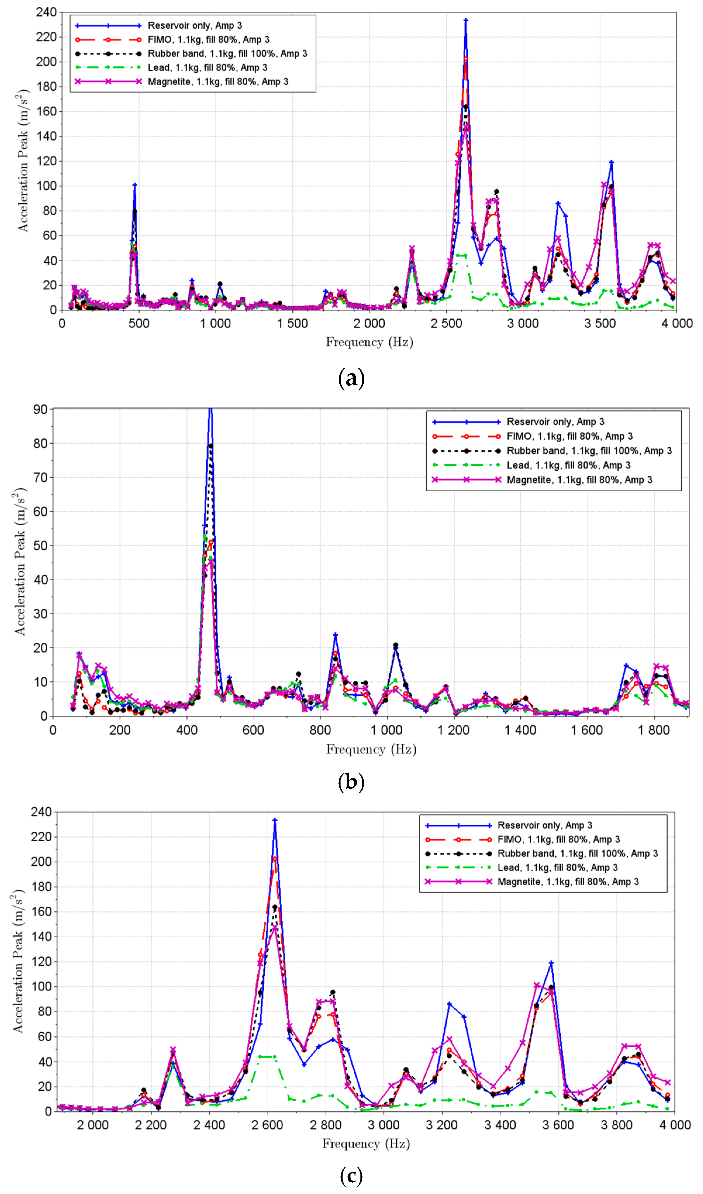
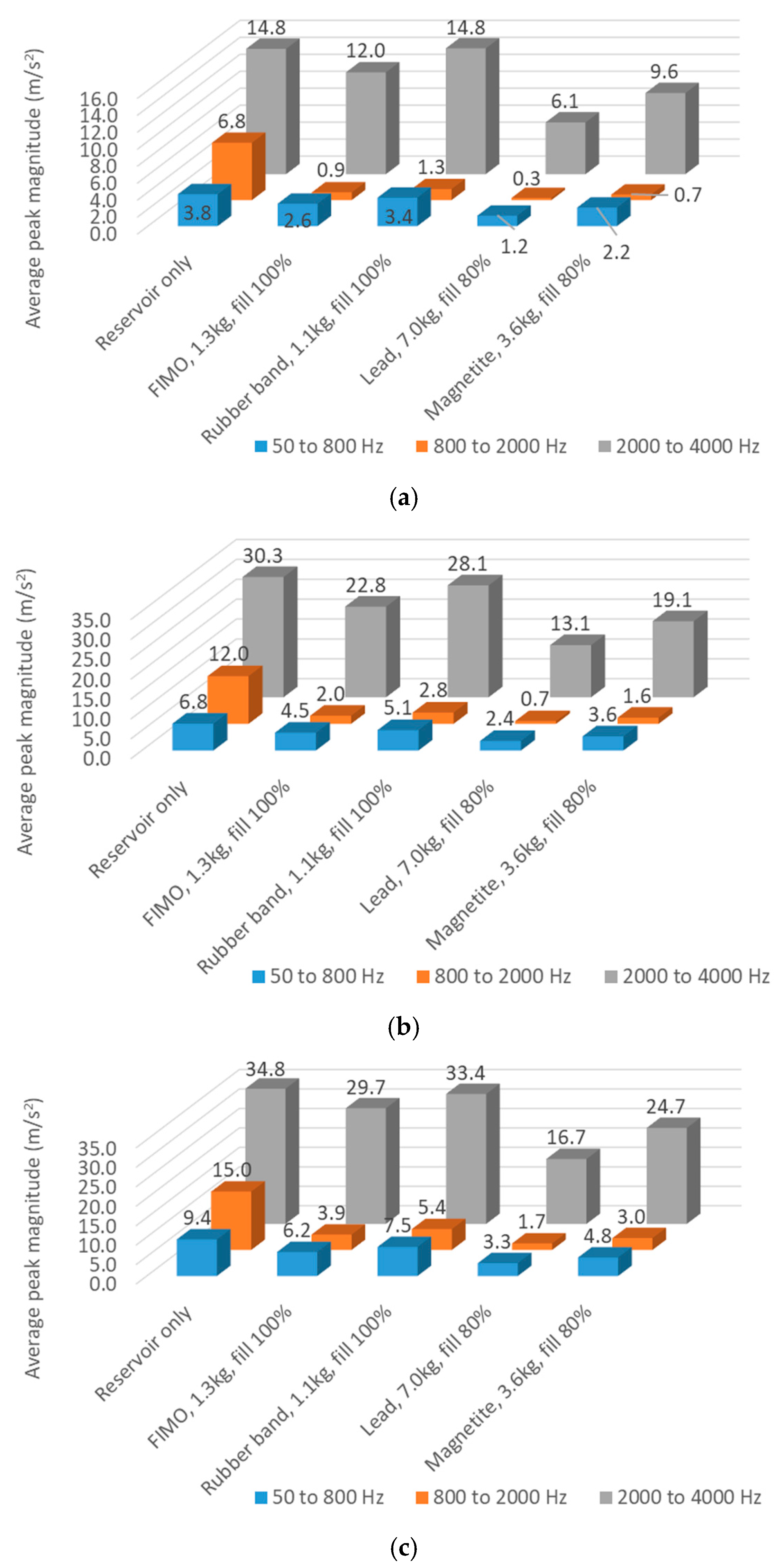
3.4. Equal Mass Comparison

This section will provide results and comparisons regarding all four particle materials, where the total particle mass (1.1 kg) was kept fixed for comparison purposes. A standard filling of 80% was used for the comparison, and it was used in all cases but one. Once the rubber band reservoir was completely filled (100%) for the reference mass, it was not possible to test this material in the partially filled condition. Figure 7a presents the results for the entire frequency range (from 50 Hz to 4000 Hz). The results containing lower frequencies are presented in Figure 7b. For this range, it can be seen that at very low frequencies, up to 250 Hz approximately, FIMO and rubber band systems yielded better results. This might be associated with the smaller individual particle mass of these cases, due to their low density, which some authors correlate with better damping at lower frequencies (and higher individual particle mass is also correlated with better efficiency at higher frequencies), as stated by Xu et al. [26]. After that range, natural rubber results are not very promising when compared with the other particles. Regarding the peak vibration for lower frequencies, around approximately 450 Hz, magnetite powder presented the greatest vibration reduction (from 100 m/s2 to 45 m/s2), closely followed by FIMO and lead particles. After approximately 1100 Hz, lead spheres presented the best vibration damping.
Regarding the opposite frequency spectrum, the higher ones, Figure 7c presents an overview of the behaviour of the four particle types analysed in this work. Once more, lead particles proved to be more efficient for the higher frequency spectrum, extending from 1100 Hz up to 4000 Hz (the maximum analysed frequency). After lead, FIMO particles were the ones that presented the best vibration damping (except for the peak amplitude at approximately 2600 Hz).

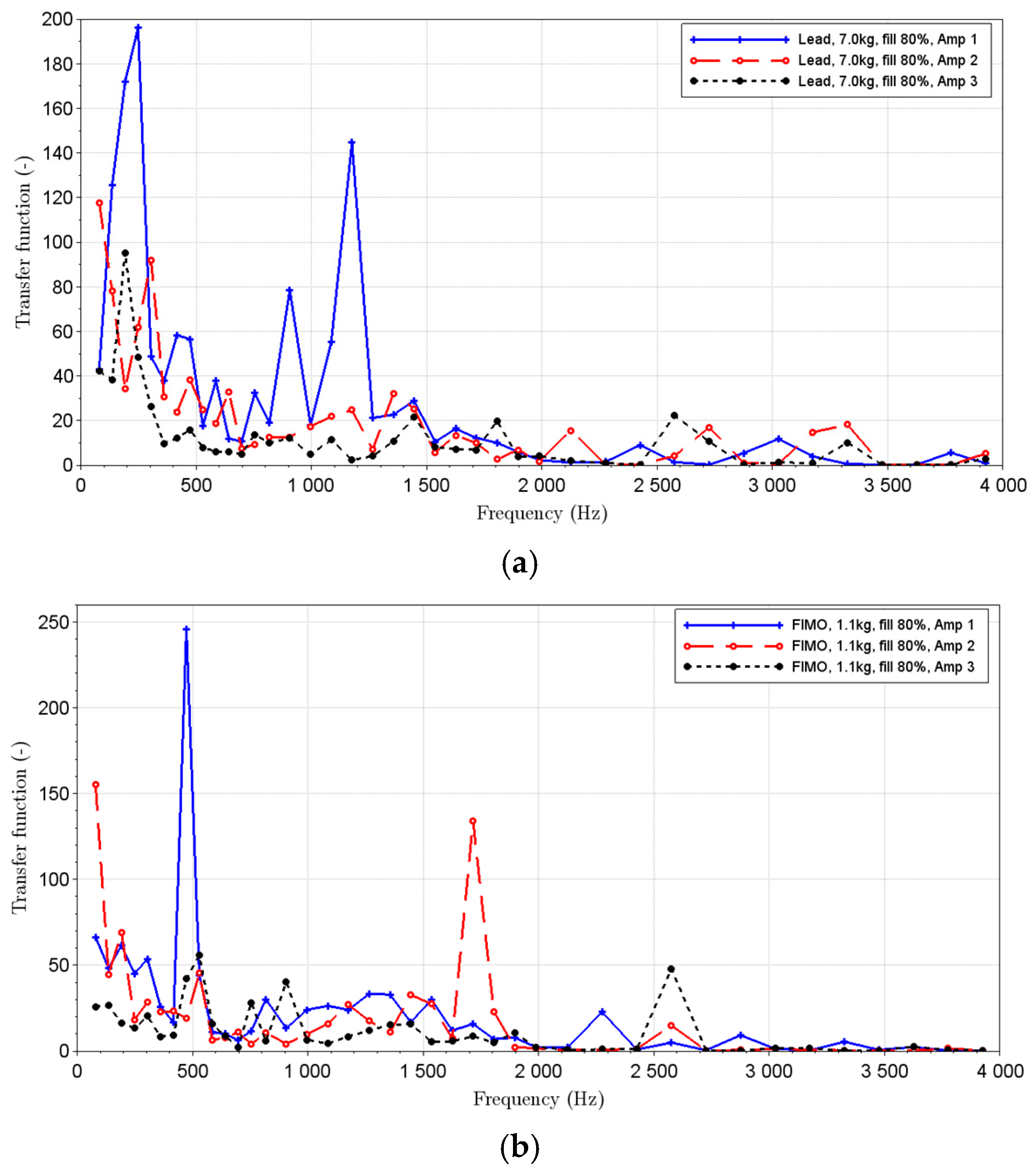
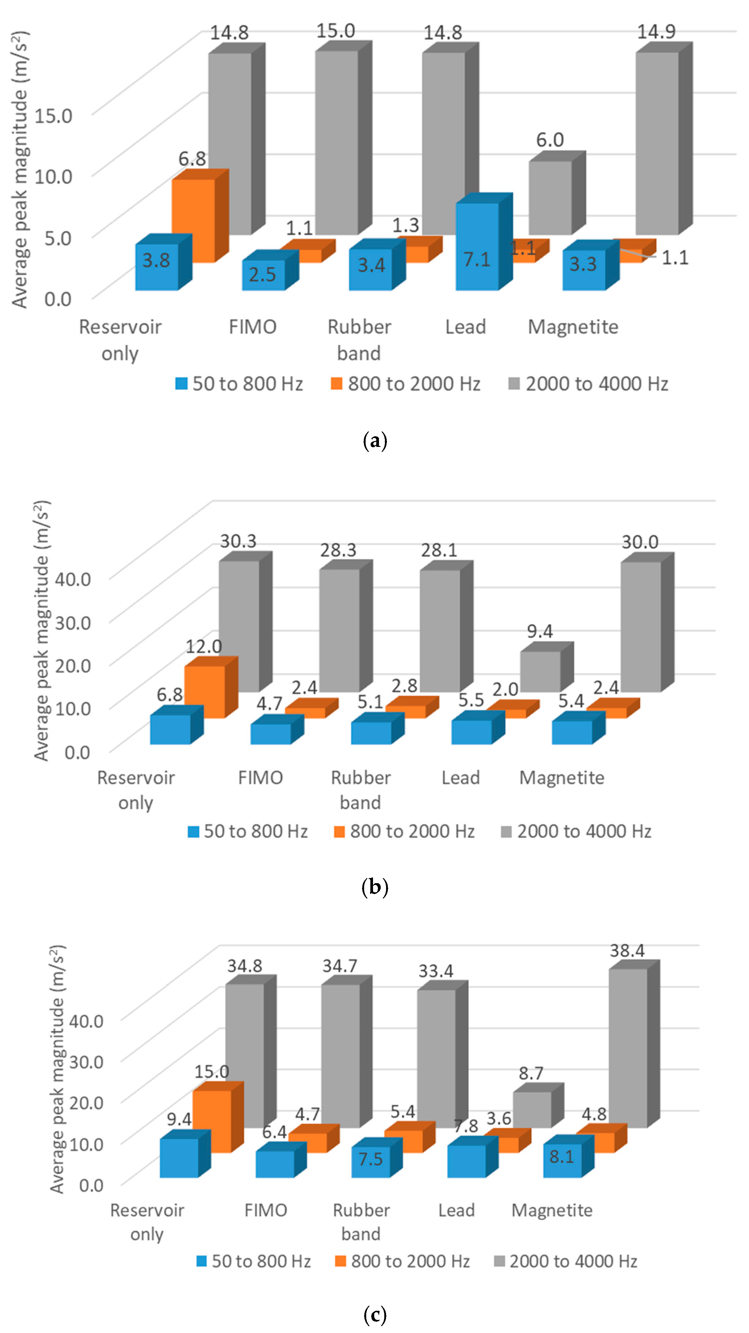
3.5. Effect of Excitation Amplitude

Additionally, besides the particle’s total mass and material effect in the vibration damping of a given system, the effect of the excitation amplitude will also be analysed. It is important to emphasise that this analysis would not be required if a linear relationship between system input (excitation) and output (vibration response) were presented in the system. However, particle dampers do not present such kind of behaviour. Consequently, the presented FRF is only valid for the excitation amplitudes analysed and should not be extrapolated to other excitation magnitudes.
The amplitude effect was analysed for two materials: lead and FIMO. All three excitation amplitudes were used for comparison, and the analysis was carried out in the frequency domain. Figure 8a presents the results obtained for lead spheres. It can be observed that as the excitation amplitude increases (from Amp1, 4 m/s2, up to Amp3, 12 m/s2), the overall relationship between output and input (transfer function) decreases. It is important to note that, although the average amplitudes were reduced, new vibration peaks appeared for high amplitudes, like one around 1700 Hz for Amp2 and one located approximately at 2500 Hz for Amp3. In other words, for the analysed frequency and amplitude ranges, it was observed that the particle-damper efficiency increases with the increment of the excitation amplitude.
A similar behaviour was observed for FIMO, presented in Figure 8b. Once more, when excited with the smallest amplitude, the system presented a higher proportional response when compared to higher external excitations (like the intermediate or highest amplitude).

3.6. Summary

The present section will provide a summary of the results. As discussed before, three frequency ranges were used. For each frequency range, average values regarding peak values will be presented for each material. Two comparisons will be performed, one presenting the same total particle mass for all four materials, while the remaining case will showcase the best configuration for each material. Although some mass configurations performed better than others in specific frequency ranges and amplitudes, the overall best will be used.
Figure 9 presents the summary results for the same total mass comparison, 1.1 kg, across the three frequency ranges and amplitudes. All cases were analysed with an 80% filling ratio, except for the rubber band, which was tested at 100% (once the reservoir was completely full). Figure 9a presents the results for the lowest excitation amplitude. Regarding the lowest frequency range, 50 to 800 Hz, the FIMO presents the highest attenuation, while lead shows the worst results. On the other hand, for intermediate and higher frequencies, lead presents the best behaviour, attenuating the vibrations’ average amplitudes by approximately 6.0 and 2.5 times for the intermediate and highest frequencies, respectively.
Figure 9b,c presents the results for the intermediate and highest excitation amplitudes. It can be observed that the overall damping behaviour of lead particles has improved, even for the lowest frequency (where lead presented the worst results for the lowest excitation amplitude). One hypothesis is that, when the excitation amplitude is very small, not enough energy is provided to generate significant movement of the lead particles (which are the heaviest among the analysed ones). Moreover, regarding the lowest frequency range, FIMO presented the best behaviour for all three analysed excitation amplitudes. Additionally, rubber bands present good results for low excitation amplitudes and frequencies, probably associated with their low particle mass (which requires less energy to move and results in more frequent collisions with other particles).
Regarding the comparison presenting the best results for each configuration, Figure 10 shows a summary of these data. The lowest excitation amplitude is presented in Figure 10a. This time, lead presents the best results for all analysed frequencies. It is important to emphasise that this mass configuration of lead had 7.0 kg of particles, nearly six times more than FIMO and a rubber band. By using lead particles, attenuation factors of 3, 20 and 2.5 times were obtained for the lowest, intermediate, and highest frequencies, respectively. Magnetite also presented good results. Once again, magnetite was the second heaviest configuration, with a particle mass of 3.6 kg. Next, FIMO presented good attenuation factors, especially for the lowest and intermediate frequency ranges.
Figure 10b,c presents the results regarding intermediate and highest excitation amplitudes. Once again, the best results were obtained using lead particles (heaviest particles and total particle mass), followed by magnetite configuration. In some cases, attenuation factors of approximately 10 were obtained, like in the case of intermediate frequencies and highest amplitudes. As was observed before, FIMO and rubber band particles presented low attenuation for the highest excitation frequencies.
Figure 11a–c displays the analysis regarding the impact of filling ratio. As discussed before, the same particle mass of 1.1 kg was used for all cases, and filling ratios of 100% and 80% were analysed. Once it was not possible to perform tests using natural rubber for 1 kg and an 80% filling ratio, this material was not used for the present comparison. It can be observed that for the lowest and highest frequency ranges analysed, a partial filling ratio (80%) presented an overall better damping performance than the counterpart (100% filling). This can be explained by the operating principle of the particle dampers, which relies on the movement and impact of the particles, being less prominent on a completely full reservoir. For the intermediate particle range (800 to 2000 Hz), no noticeable difference was found regarding different filling rates. It is important to emphasise that, for the present study, this frequency range also presented the lowest vibration amplitudes, which might not be sufficient to create significant particle motion, resulting in the particles behaving like a fixed mass (without relevant collisions between the particles and the reservoir).

4. Conclusions and Future Work

It was observed that the particle damper systems were capable of efficiently reducing the vibration levels for the frequency ranges and excitation amplitudes studied in the present work. When comparing the performance of different particle materials, the lead spheres proved to be the most efficient solution for the conditions analysed. In some cases, the particle dampers were capable of reducing peak vibrations by more than 20 times.
Moreover, it was observed that the studied particle-damping systems were more efficient when larger levels of vibrations were present (for example, in the natural frequencies of the railway track), especially for denser particles like lead and magnetite. Additionally, it was detected that the total particle mass has a stronger impact on reducing vibration levels at lower frequencies. Finally, in cases where the reservoir was completely filled with particles (100% fill), it was noticed that the particle-damping efficiency was reduced when compared to partially filled reservoirs (for the present study, 80%). This observation was in good agreement with the literature. Once the reservoir is completely filled, the particles do not have enough space to move and collide with each other. Since the collisions and friction between particles are intrinsic characteristics, they affect the particle dampers’ efficiency and are the main components for energy dissipation. This loss in efficiency can be easily explained.
As it was observed in the literature, each type of particle might be very effective at a specific frequency and amplitude range. In the present study, it was observed that FIMO and rubber bands (the lightest particles) presented good vibration attenuation for low excitation amplitudes and low frequencies. On the other hand, lead particles proved to be very effective in attenuating vibration levels at higher frequencies. Consequently, the best material must be chosen by taking into account the target frequency range, and even a combination of materials might be used to cover different frequency ranges. Analysing the average amplitude values for the entire set of frequency ranges and amplitudes, lead particles showed to result in the best damping behaviour.
Regarding future work, a wide range of different solutions could be addressed, like analysing the reservoir design and materials, which is an essential step for a better understanding of the particle-damping systems and enhancing their performance. Studying the effects of different reservoir materials, like building and testing an acrylic reservoir, would provide interesting information. Additionally, a combination of transparent reservoir materials and high-speed cameras would provide important insights into the vibration behaviour for each material and volume filling. Moreover, studying the distribution of several smaller reservoirs and how they compare with a single one could improve the overall damper’s efficiency without the need to increase the system’s total mass. Furthermore, an analysis encompassing the particles’ granulometry (like average particle size and distribution effect) and the impact of reservoir internal divisions might help intensify the particle-damping system’s effectiveness. Lastly, the application of hybrid damping systems, like particle dampers and tuned mass dampers, could be analysed, and their efficiency compared with single-damper solutions.
Later, studies regarding the feasibility of applying the present solution in a real-case scenario would be vital, where factors like economic viability and long-term duration of the particles would be addressed.

Author Contributions

Conceptualization: A.Z.S. and A.P.C.; Methodology: A.Z.S. and Y.E.A.; Investigation: F.K.F., C.P. and A.P.C.; Writing—Original Draft: F.K.F., C.P. and T.A.F.; Software: F.K.F.; Formal analysis: F.K.F. and A.M.P.d.J. Writing—Review and Editing: Y.E.A., A.P.C. and A.M.P.d.J.; Funding Acquisition: A.M.P.d.J. and T.A.F.; Resources: A.Z.S. and Y.E.A.; Supervision: C.P., A.M.P.d.J. and T.A.F. All authors have read and agreed to the published version of the manuscript.

Funding

The authors would like to acknowledge FUNDEP for funding the present research.

Institutional Review Board Statement

Not applicable.

Informed Consent Statement

Not applicable.

Data Availability Statement

The data presented in this study are available on request from the corresponding author. The data are not publicly available due to privacy.

Conflicts of Interest

The authors declare no conflicts of interest.

References

  1. Wrótny, M.; Bohatkiewicz, J. Traffic noise and inhabitant health—A comparison of road and rail noise. Sustainability 2021, 13, 7340. [Google Scholar] [CrossRef]
  2. Maclachlan, L.; Waye, P.K.; Pedersen, E. Exploring perception of vibrations from rail: An interview study. Int. J. Environ. Res. Public Health 2017, 14, 1303. [Google Scholar] [CrossRef] [PubMed]
  3. Smith, M.G.; Croy, I.; Ögren, M.; Waye, P.K. On the influence of freight trains on humans: A laboratory investigation of the impact of nocturnal low frequency vibration and noise on sleep and heart rate. PLoS ONE 2013, 8, e55829. [Google Scholar] [CrossRef] [PubMed]
  4. Croy, I.; Smith, M.G.; Waye, K.P. Effects of train noise and vibration on human heart rate during sleep: An experimental study. BMJ Open 2013, 3, e002655. [Google Scholar] [CrossRef]
  5. Croft, B.; Miller, A.; Küpper, A. Maintenance effects on rolling noise–metro and light rail. Proc. Acoust. 2021, 21, 2022. [Google Scholar]
  6. Höjer, M.; Bergseth, E.; Olofsson, U.; Nilsson, R.; Lyu, Y. A noise related track maintenance tool for severe wear detection of wheel–rail contact. In Proceedings of the Third International Conference on Railway Technology: Research, Development and Maintenance, Caglinari, Italy, 5–8 April 2016; Civil-Comp Press: Stirlingshire, UK, 2016. [Google Scholar]
  7. Zhang, J.; Xiao, X.; Wang, D.; Yang, Y.; Fan, J. Source Contribution Analysis for Exterior Noise of a High-Speed Train: Experiments and Simulations. Shock Vib. 2018, 1, 5319460. [Google Scholar] [CrossRef]
  8. Connolly, D.P.; Marecki, G.P.; Kouroussis, G.; Thalassinakis, I.; Woodward, P.K. The growth of railway ground vibration problems—A review. Sci. Total Environ. 2016, 568, 1276–1282. [Google Scholar] [CrossRef]
  9. Ogran, M.; GIdlof-Gunnarsson, A.; Smith, M.; Gustavsson, S.; Waye, K.P. Comparison of annoyance from railway noise and railway vibration. Int. J. Environ. 2017, 14, 805. [Google Scholar]
  10. Sanayei, M.; Maurya, P.; Moore, J.A. Measurement of building foundation and ground-borne vibrations due to surface trains and subways. Eng. Struct. 2013, 53, 102–111. [Google Scholar] [CrossRef]
  11. Zou, C.; Wang, Y.; Moore, J.A.; Sanayei, M. Train-induced field vibration measurements of ground and over-track buildings. Sci. Total Environ. 2017, 575, 1339–1351. [Google Scholar] [CrossRef]
  12. Hanson, C.E.; Towers, D.A.; Meister, L.D. Transit Noise and Vibration Impact Assessment; Federal Transit Administration (USA): Washington, DC, USA, 2006. [Google Scholar]
  13. Abramov, A.; Podorozkina, A.; Bilenko, G.; Ivankova, L.; Okulova, M. Optimization of Freight Train Speeds on Railway Transport. Transp. Res. Procedia 2022, 61, 371–375. [Google Scholar] [CrossRef]
  14. Thompson, D.J.; Jones, C.J.C. A review of the modelling of wheel/rail noise generation. J. Sound Vib. 2008, 231, 519–536. [Google Scholar] [CrossRef]
  15. Thompson, D.J. On the relationship between wheel and rail surface roughness and rolling noise. J. Sound Vib. 1996, 193, 149–160. [Google Scholar] [CrossRef]
  16. Jeong, D.; Choi, H.S.; Choi, Y.J.; Jeong, W. Measuring Acoustic Roughness of a Longitudinal Railhead Profile Using a Multi-Sensor Integration Technique. Sensors 2019, 19, 1610. [Google Scholar] [CrossRef]
  17. Smith, M.G.; Croy, I.; Hammar, O.; Wayer, K.P. Vibration from freight trains fragments sleep: A polysomnographic study. Sci. Rep. 2016, 6, 24717. [Google Scholar] [CrossRef]
  18. Elias, S.; Matsagar, V. Research developments in vibration control of structures using passive tuned mass dampers. Annu. Rev. Control 2017, 44, 129–156. [Google Scholar] [CrossRef]
  19. Jangid, R.S.; Datta, T.K. Seismic behaviour of base-isolated buildings: A state-of-the art-review. Proc. Inst. Civ. Eng. Struct. Build. 1995, 110, 186–203. [Google Scholar] [CrossRef]
  20. Saidi, I.; Mohammed, A.D.; Gad, E.F.; Wilson, J.L.; Haritos, N. Optimum Design for Passive Tuned Mass Dampers Using Viscoelastic Materials; Australian Earthquake Engineering Society: Wollongong, Australia, 2007. [Google Scholar]
  21. Jin, J.; Yang, W.; Koh, H.; Park, J. Development of tuned particle impact damper for reduction of transient railway vibrations. Appl. Acoust. 2020, 169, 107487. [Google Scholar] [CrossRef]
  22. Lin, C.C.; Wang, J.F.; Chen, B.L. Train-induced vibration control of high-speed railway bridges equipped with multiple tuned mass dampers. J. Bridge Eng. 2005, 10, 398–414. [Google Scholar] [CrossRef]
  23. Gagnon, L.; Morandini, M.; Ghiringhelli, G.L. A review of particle damping modeling and testing. J. Sound Vib. 2019, 459, 114865. [Google Scholar] [CrossRef]
  24. Friend, R.D.; Kinra, V.K. Particle impact damping. J. Sound Vib. 2000, 233, 93–118. [Google Scholar] [CrossRef]
  25. Meyer, N.; Seifried, R. Design of robust particle dampers using inner structures and coated container walls. Granul. Matter 2023, 25, 10. [Google Scholar] [CrossRef]
  26. Xu, Z.W.; Chan, K.W.; Liao, W.H. An empirical method for particle damping design. Shock Vib. 2004, 11, 647–664. [Google Scholar] [CrossRef]
  27. Prasad, B.B.; Duvigneau, F.; Woschke, E.; Juhre, D. Application and damping mechanism of particle dampers. Proc. Appl. Math. Mech. 2023, 22, e202200116. [Google Scholar] [CrossRef]
  28. Veeramuthuvel, P.; Shankar, K.; Sairajan, K.K. Experimental investigation of particle damper-based vibration suppression in printed circuit board for spacecraft applications. Proc. Inst. Mech. Eng. Part G J. Aerosp. Eng. 2015, 230, 1299–1311. [Google Scholar] [CrossRef]
  29. Paul, P.S.; Raja, P.; Aruldhas, P.; Pringle, S.; Shaji, E. Effectiveness of particle and mass impact damping on tool vibration during hard turning process. Proc. Inst. Mech. Eng. Part B J. Eng. Manuf. 2018, 232, 776–786. [Google Scholar] [CrossRef]
  30. Panossian, H.V. Structural Damping Enhancement Via Non-Obstructive Particle Damping Technique. J. Vib. Acoust. 1992, 114, 101–105. [Google Scholar] [CrossRef]
  31. Prasad, B.B.; Luft, T.; Michaelsen, C.; Rottengruber, H.S. Enhancing Vibroacoustic Performance of Power Electronic Subsystem in Electric Drives Using Particle Dampers. In Proceedings of the DAGA 2024, Hannover, Germany, 18–21 March 2024. [Google Scholar]
  32. Xin, Y. Deep learning-based investigation of an innovative rail damper using particle damping technology for noise and vibration control. Ph.D. Thesis, The Hong Kong Polytechnic University, Hong Kong, 2024. [Google Scholar]
  33. Liu, C.; Lai, S.; Ni, Y.; Chen, L. Dynamic modelling and analysis of a physics-driven strategy for vibration control of railway vehicles. Veh. Syst. Dyn. 2024, 1–31. [Google Scholar] [CrossRef]
  34. Zhang, C.; Kordestani, H.; Shadabfar, M. A combined review of vibration control strategies for high-speed trains and railway infrastructures: Challenges and solutions. J. Low Freq. Noise Vib. Act. Control. 2023, 42, 272–291. [Google Scholar] [CrossRef]
  35. Jin, J.; Kim, H.; Koh, H.I.; Park, J. Railway noise reduction by periodic tuned particle impact damper with bounce and pitch-coupled vibration modes. Compos. Struct. 2022, 284, 115230. [Google Scholar] [CrossRef]
  36. Lu, Z.; Zhang, Q.; Fan, Q.; Li, Q. Studies on dissipative characteristics and equivalent model of particle damper in railway application. J. Sound Vib. 2023, 560, 117788. [Google Scholar] [CrossRef]
  37. Yanning, T.; Yu, D.; Wangqiang, X.; Kun, X. Particle damping-based design for vibration and noise reduction of interior wooden flooring in high-speed railway trains. Railw. Roll. Stock 2024, 1, 85–92. [Google Scholar]
  38. Cuenot, S.; Frétigny, C.; Demoustier-Champagner, S.; Nysten, B. Surface tension effect on the mechanical properties of nanomaterials measured by atomic force microscopy. Phys. Rev. B 2004, 69, 165410. [Google Scholar] [CrossRef]
  39. Chicot, D.; Mendoza, J.; Zaoui, A.; Louis, G.; Lepingle, V.; Roudet, F.; Lesage, J. Mechanical properties of magnetite (Fe3O4), hematite (α-Fe2O3) and goethite (α-FeO·OH) by instrumented indentation and molecular dynamics analysis. Mater. Chem. Phys. 2011, 129, 862–870. [Google Scholar] [CrossRef]
  40. Vo, V.S.; Nguyen, V.; Mahouche-Chegui, S.; Carbonnier, B.; Naili, S. Estimation of effective elastic properties of polymer/clay nanocomposites: A parametric study. Compos. Part B Eng. 2018, 152, 139–150. [Google Scholar] [CrossRef]
  41. Koblar, D.; Škofic, J.; Boltežar, M. Evaluation of the Young’s Modulus of Rubber-Like Materials Bonded to Rigid Surfaces with Respect to Poisson’s Ratio. J. Mech. Eng. 2014, 60, 506–611. [Google Scholar] [CrossRef]
Figure 1. Steel rail and particle reservoir testing setup: (a) Testing setup overview, top view; (b) Testing setup overview, front view; (c) Schematic view, front view; (d) Reservoir.
Applsci 15 05014 g001
Figure 2. Types of particles used for the damping systems.
Applsci 15 05014 g002
Figure 3. Example of time and frequency domain measurement, maximum excitation amplitude (12 m/s2): (a) Time-domain signal; (b) Frequency-domain signal.
Applsci 15 05014 g003
Figure 4. Lead particles, excitation amplitude of 12 m/s2, time-domain analysis: (a) Overview; (b) Lower frequency band; (c) Higher frequency band; (d) Filling ratio comparison, equal mass.
Applsci 15 05014 g004
Figure 5. Magnetite particles, excitation amplitude of 12 m/s2, time-domain analysis: (a) Overview; (b) Lower frequency band; (c) Higher frequency band.
Applsci 15 05014 g005
Figure 6. Polymeric clay (FIMO) and rubber band particles, excitation amplitude of 12 m/s2, time-domain analysis: (a) Overview; (b) Lower frequency band; (c) Higher frequency band.
Applsci 15 05014 g006
Figure 7. Equal particle mass, 1.1 kg, excitation amplitude of 12 m/s2, time-domain analysis: (a) Overview; (b) Lower frequency band; (c) Higher frequency band.
Applsci 15 05014 g007
Figure 8. Effect of excitation amplitude on vibration response, comparison of the lowest and highest excitation amplitudes, frequency-domain analysis: (a) Lead particles; (b) FIMO particles.
Applsci 15 05014 g008
Figure 9. Equal mass comparison for all materials: (a) Lowest excitation amplitude; (b) Intermediate excitation amplitude; (c) Highest excitation amplitude.
Applsci 15 05014 g009
Figure 10. Best case comparison for all materials: (a) Lowest excitation amplitude; (b) Intermediate excitation amplitude; (c) Highest excitation amplitude.
Applsci 15 05014 g010
Figure 11. Impact of filling ratio on vibration: (a) Lowest excitation amplitude; (b) Intermediate excitation amplitude; (c) Highest excitation amplitude.
Applsci 15 05014 g011
Table 1. Measuring system information.
SensorSensitivityMeasuring Range
Dytran 5860B—impedance head, Chatsworth, CA, USAaccelerometer10.43 mV/(m/s2)1.0 to 8000 Hz
force transducer23.18 mV/N1.0 to 8000 Hz
Bruel and Kjaer 4508 b, Nærum, Denmarkaccelerometer9.73 mV/(m/s2)0.3 to 8000 Hz
Table 2. Loading amplitudes and excitation frequencies.
Start Excitation Frequency (Hz)End Excitation Frequency (Hz)Excitation Acceleration Amplitude (m/s2)
508004, 8 and 12
80020004, 8 and 12
200040004, 8 and 12
Table 3. Particle materials, size, and density.
MaterialsAverage Particle Size (mm)Bulk Density (kg/m3)Elasticity Modulus (GPa)
Lead spheres2.3650016 [38]
Magnetite powder0.32400200 [39]
Polymer clay (FIMO)3.07004 [40]
Natural rubber5.06003 [41]
Table 4. Testing conditions, materials, total particle mass, and filling ratios.
MaterialsParticles Mass (kg)Filling Ratio (%)
Lead spheres7.9 and 1.1100
7.9, 5.7 and 1.180
Magnetite powder4.5 * and 1.1100
3.5 and 1.180
Polymer clay (FIMO)1.3 * and 1.1100
1.180
Natural rubber1.1 *100
0.980
Note: Conditions marked with an asterisk, *, represent the reservoir completely filled, with the cover at the utmost position (maximum volume).
Disclaimer/Publisher’s Note: The statements, opinions and data contained in all publications are solely those of the individual author(s) and contributor(s) and not of MDPI and/or the editor(s). MDPI and/or the editor(s) disclaim responsibility for any injury to people or property resulting from any ideas, methods, instructions or products referred to in the content.

