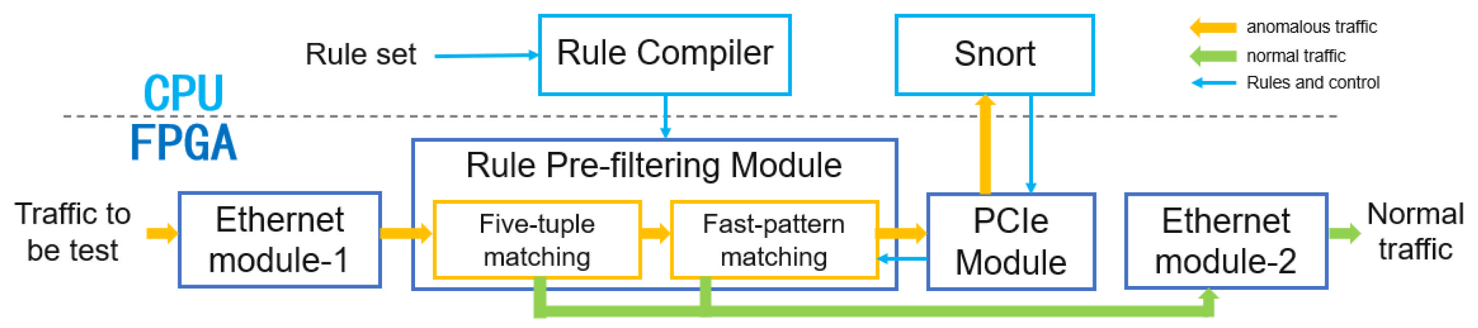
Based on the flexible and convenient characteristics of software development and its strong adaptability, two functional modules have been deployed on the CPU side, including the rule compilation module and the Snort module, to ensure the complete operation of the heterogeneous network intrusion detection system. The following is a detailed description of the functionalities of the two modules:
3.3.1. Rule Compilation Module
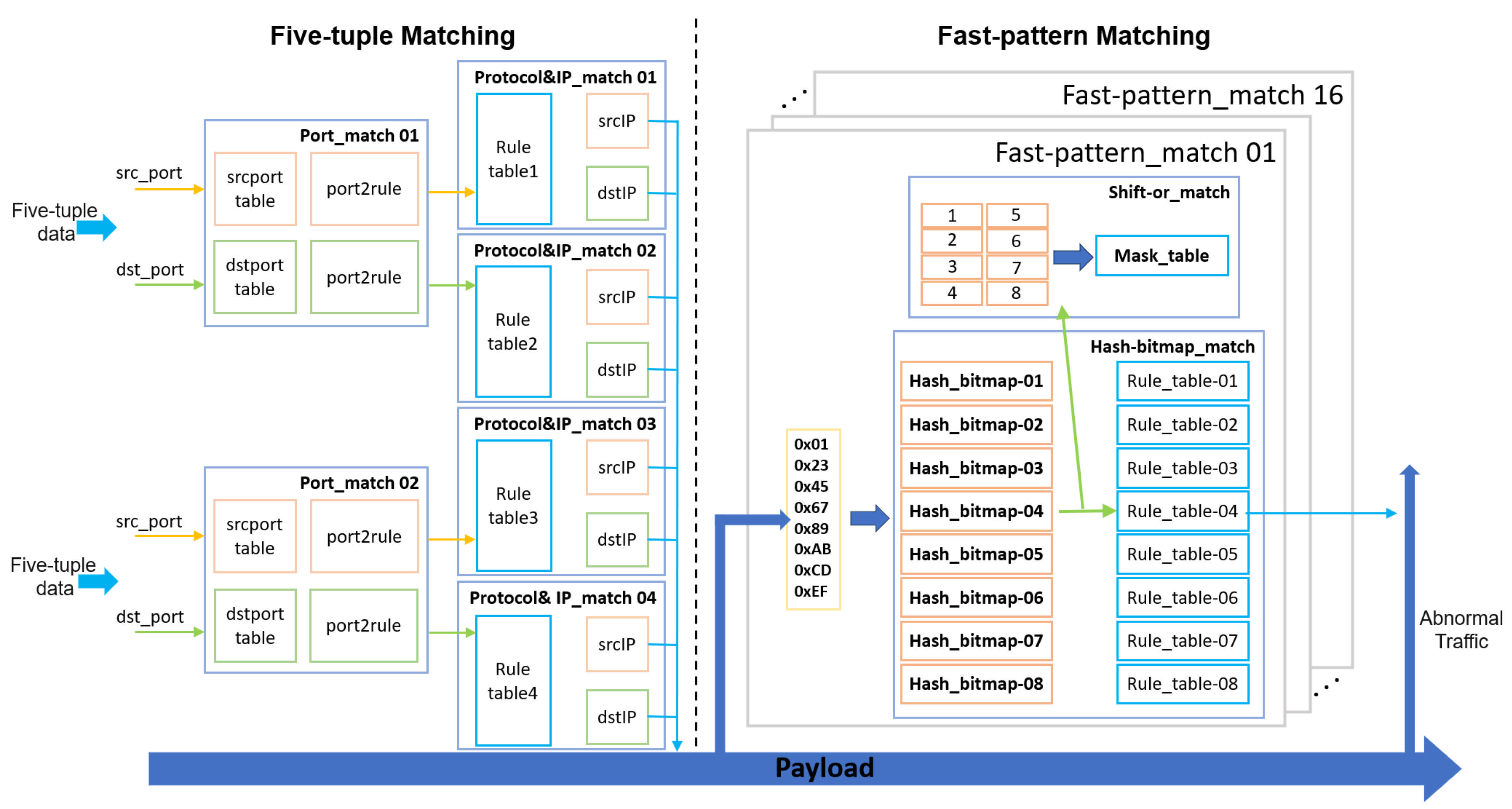
This module compiles Snort rule data into segmented memory files for FPGA-based matching. To enhance overall matching efficiency and optimize FPGA memory utilization, the rule set undergoes preprocessing and compilation workflow optimization. The implementation integrates five-tuple segmented matching and fast-pattern bit-parallel matching designs.
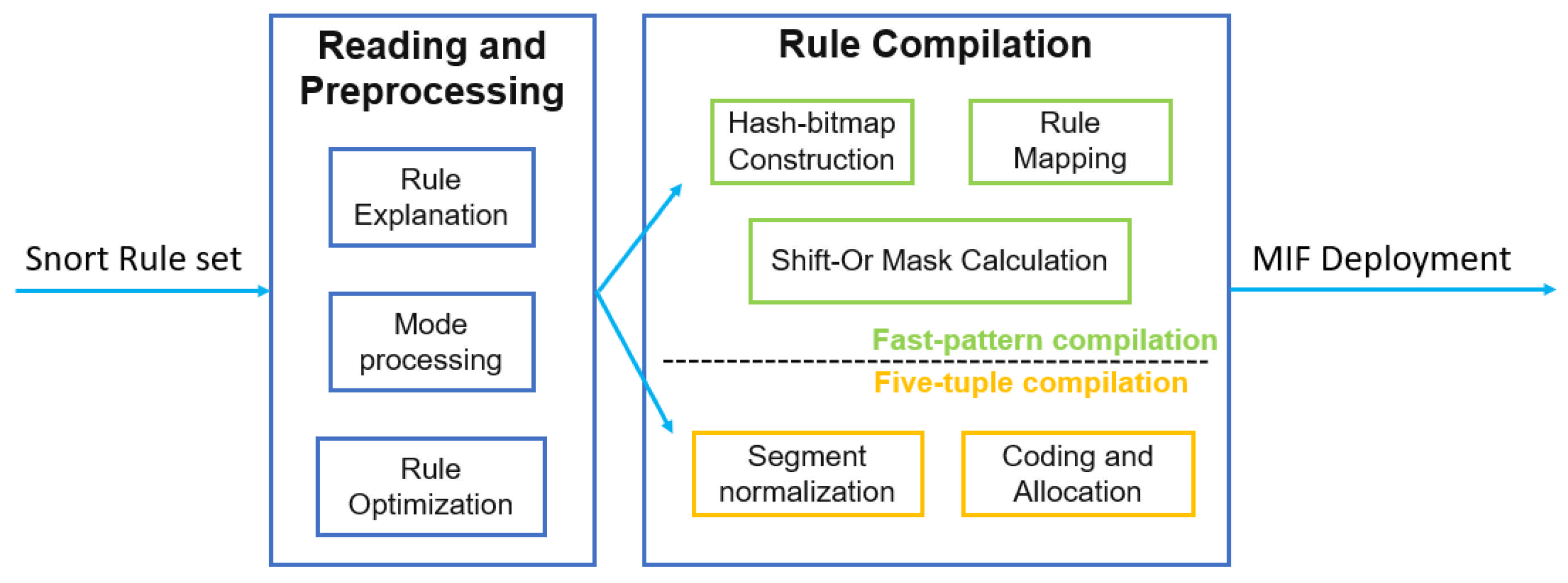
As illustrated in
Figure 3, when a Snort rule set is loaded into the compilation module, rule parsing is first executed to extract and convert fields such as five-tuple (source/destination IP/port, protocol) and content. Subsequent pattern processing and rule optimization steps involve field splitting, wildcard expansion, and rule merging.
A concrete example is provided to elucidate the compilation design. After parsing, the five-tuple information and SID are fed into the five-tuple compilation submodule (e.g., variables like $HOME_NET, $EXTERNAL_NET, and $SIP_PORTS are predefined in Lua configuration files and resolved during parsing). The compilation process handles ports, protocols, and IPs as follows:
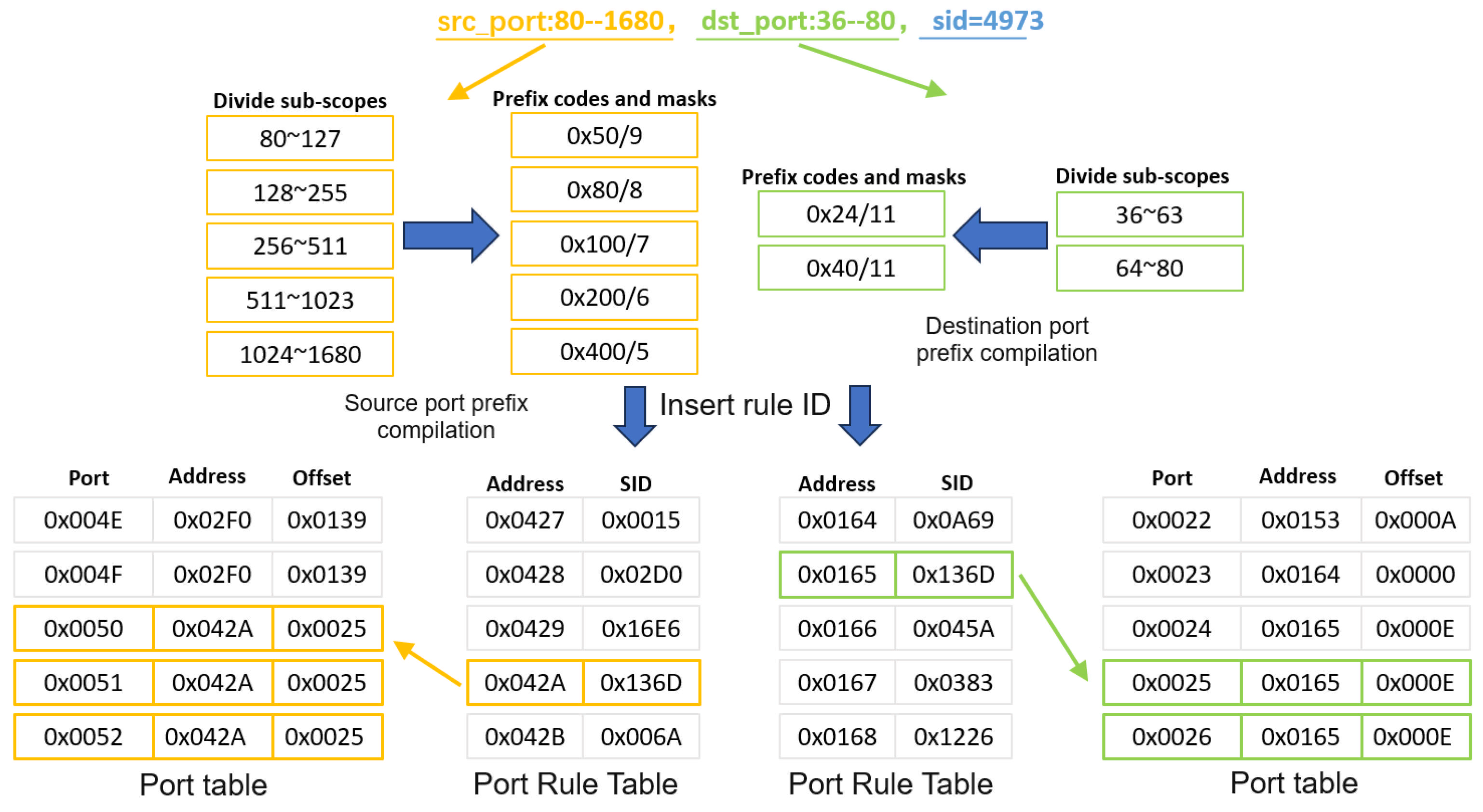
Port Compilation. Snort rules define ports as three types: exact port numbers, port ranges, or any. To address mixed port specifications, an interval prefix mask is employed to partition ranges into subintervals and detect source/destination port matches. Since multiple rules may share overlapping port ranges, the compiler dynamically updates source/destination port rule tables, encoding matched rules as “address + offset” entries for efficient lookup.
As shown in
Figure 4, for a rule with src_port: 80–1680, dst_port: 36–80, and sid = 4973, the compiler splits the source/destination port ranges into subintervals, computes maximal prefix masks, and inserts the rule ID into corresponding port tables. Addresses and offsets in the port tables are updated to reflect all matching rules.
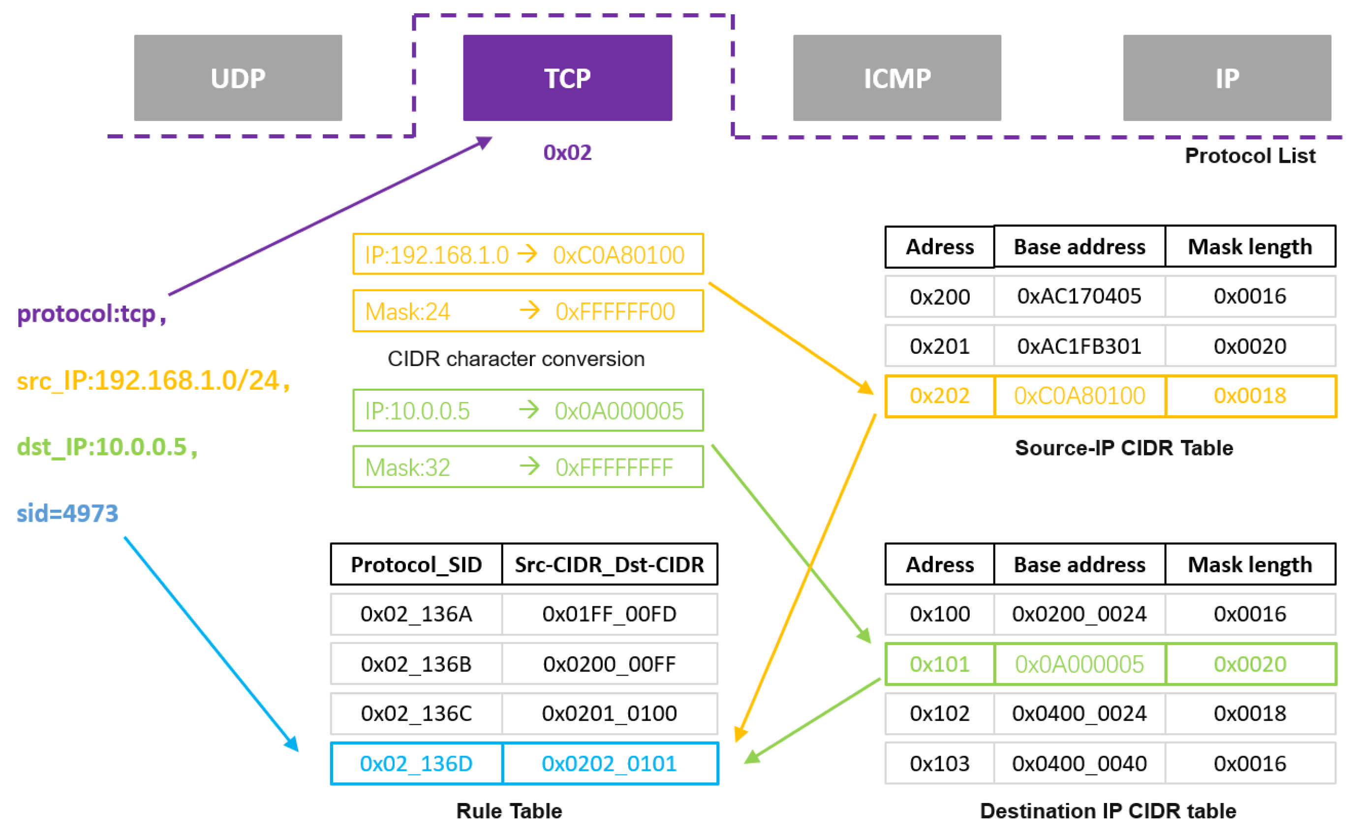
Protocol and IP Compilation. Snort rules include four protocol types: UDP, TCP, ICMP, and IP. To improve matching efficiency, we designed a “protocol + IP” compilation mode: distinguishing IP lookup tables by protocols to narrow the scope of IP matching. The four protocols are represented as “0x01, 0x02, 0x03, and 0x04”, respectively. The IP address types in rule files are divided into precise IP addresses, CIDR [
38] addresses, and IP lists. Due to their complexity, we uniformly convert IP addresses to CIDR format during compilation, store them in protocol-specific CIDR tables, and establish a rule table to store two groups of corresponding CIDR addresses and rule IDs to match the relevant rules. As shown in
Figure 5, we detail this compilation design through the example rule “protocol:tcp, src_IP: 192.168.1.0/24, dst_IP: 10.0.0.5, sid = 4973”:
First, classify according to the protocol type in the rule. For example, the “TCP” protocol is encoded as “0x02”. Then, extract the source IP and destination IP from the rule and perform CIDR conversion. Through the combination of masks and prefix codes, both precise IP addresses and CIDR-format IP address sets can be converted one-to-one to obtain a 32-bit base address and 16-bit mask length. The source IP and destination IP are stored in two separate CIDR tables. If entries duplicate previous content, merging is required. Finally, based on the CIDR addresses in the two tables, store them in the rule table in the format “SID_sourceCIDR_destCIDR” (48 bits total). This completes the protocol and IP address compilation, finalizing the five-tuple rule compilation.
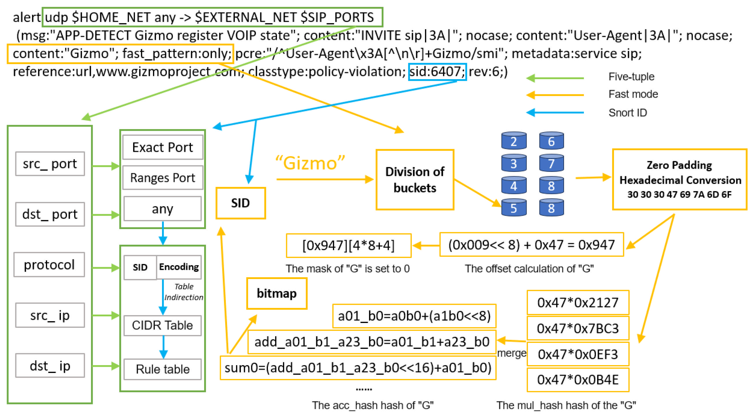
After completing the five-tuple rule compilation, the system enters the fast-pattern compilation phase. Since nearly 70% of data packets require fast-pattern detection, the compilation quality of this module directly affects system throughput and detection accuracy, posing significant challenges to compiler design. To achieve 100 Gbps line-speed processing capability, we integrate hash functions with bitmaps to realize memory-efficient access through the hash-discretized distribution characteristics of fast-pattern strings. The shift-or exact matching algorithm is incorporated to eliminate hash bitmap false positives and improve detection accuracy. Finally, we establish a strict binding mechanism between rule IDs and hash addresses to avoid mismatching risks. The three-part compilation design is as follows:
Hash Bitmap [39,40] construction. Taking
Figure 6 as an example, “Gizmo” is the fast-pattern string extracted by the compiler. First, according to the length of the extracted fast-pattern string, it is assigned to a specified bucket, and then converted to ASCII values. Since the string length is less than 8 bytes, zeros need to be padded to the higher bits of the string to ensure input consistency of the hash function, while padding “0” can make the result differences more distinct. Subsequently, hash computation is performed to generate bitmap indices. We designed two hash functions: one performs multiplication operations, and the other performs hierarchical addition and bit shifting, aiming to obtain completely distinct hash addresses.
First, the input 8-byte characters are split. To make the calculated addresses as evenly distributed as possible, the data are multiplied with four predefined 16-bit constants split from the constant “0x0b4e0ef37bc32127”. The specific calculation formula is shown in Listing 1.
| Listing 1. mul_hash formula. |
| 1. uint64_t b = 0x0b4e0ef37bc32127; |
| 2. uint16_t bn[4]; |
| 3. uint64_t tmpb = b; |
| 4. for(int i = 0; i < 4; i++){ |
| 5. bn[i] = tmpb; |
| 6. tmpb = (tmpb ≫ 16); |
| 7. } |
| 8. Mulhash_res res; |
| 9. for(int i = 0; i < 4; i++){ |
| 10. res.ab_n[i] = a * bn[i]; |
| 11. } |
In the formula, a is the ASCII value of the character, and bn[i] represents the four 16-bit constants split from the predefined constant. Through calculation, each character obtains four corresponding multiplicative hash values, denoted as ab_n[i].
Then, the above multiplicative values are input into the hierarchical addition and shifting part. Adjacent characters and cross-character addition combinations are calculated. After hierarchical merging and extracting high-order bits, the final hash address is obtained through addition and shifting. The relevant calculation formulas are shown in Listing 2.
| Listing 2. acc_hash formula. |
| 1. uint64_t a01_b0 = aibj[0].ab_n[0] + (aibj[1].ab_n[0] ≪ 8); |
| 2. … |
| 3. uint64_t add_a01_b1_a23_b0 = a01_b1 + a23_b0; |
| 4. … |
| 5. uint64_t sum0 = (add_a01_b1_a23_b0 ≪ 16) + a01_b0; |
| 6. uint64_t sum1 = add_a01_b2_a45_b0 + a23_b1; |
| 7. uint64_t sum2 = (add_a01_b3_a23_b2 |
| 8. uint64_t half_sum0 = sum0; |
| 9. uint64_t half_sum1 = (sum2 ≪ 16) + sum1; |
| 10. uint64_t sum = half_sum0 + (half_sum1 ≪ 32); |
| 11. uint32_t addr = (sum >> (64 − NBITS)); |
In the formula, line 1 represents the combination calculation of adjacent characters, synthesizing a 16-bit value through left-shifting 8 bits and addition. Line 3 represents cross-character addition calculation and cross-layer mixing, aiming to increase bit diffusion and make distribution more uniform. Lines 5–7 represent hierarchical merging, combining the previously calculated values. The modulo operation on sum2 is to extract the lower 16 bits. Lines 8–10 represent the final addition of hash results, where shifting aims to avoid overlap in lower bits affecting the results. Line 11 obtains the hash address. Here, NUM_BITS is 8, so the final hash address length is 8 bits. The higher 5 bits of the hash address are taken as the bitmap address, while the bitmap offset is designed as the lower 3 bits of the hash address, setting the corresponding bit to 1. At this point, hash bitmap construction is completed.
Regarding hash collision resolution, our solution is to detect and report errors during compilation, then resolve them by modifying the fast-pattern string length or content to reclassify them into other buckets for computation.
Shift-or Mask [41] Calculation. Shift-or mask compilation is performed based on bucket partitioning. Fast-pattern strings of different lengths are assigned to different buckets to generate independent masks, simplifying mask generation logic. Simultaneously, for each bucket, we separately calculate and generate independent mask bits. For long string inputs, the module only retains fixed offset bits while clearing other offset bits, thereby avoiding interference of long patterns on short pattern matching. The specific compilation process still uses “Gizmo” as an example, with
Table 3 showing the compilation results. According to the string length, it is assigned to Bucket 3 (corresponding to 5 bytes), with offsets numbered 0 to 4 from right to left. During computation, the compiler takes the lower 5 bits of each character’s ASCII value as the calculation parameter for the previous character. For example, when “i” is followed by “z”, the index calculation is index = (0x1A << 8) + 0x69. The specific mask bits are calculated through character offsets: mask_bits = Offset ∗ 8 + (7 − 3). In the formula, “8” represents the total number of buckets, and “7” represents the maximum bucket index. If the offset is 0, the index values 0x006F-0x1F6F are set to 0 at mask bit 4 to avoid affecting other string matches.
By calculating index values and mask values, the specific row and offset in the mif file can be determined, and the corresponding bit is set to “0”, indicating that this position allows a match hit.
Rule Mapping. The purpose of rule mapping is to bind fast-pattern strings to rule IDs, enabling quick retrieval of rule IDs via hash address lookups when matches occur. The specific mapping operation is using the calculated hash address as the mif address, where the stored value corresponds to the rule ID.
Based on the above compiler design, we summarize the specifications of mif files generated by compiling 10,000 rules through each module in
Table 4:


