Article

Inverse Design of Broadband Artificial Magnetic Conductor Metasurface for Radar Cross Section Reduction Using Simulated Annealing

by
Haoda Xia
1,
Xiaoyu Liang
1,
Bowen Jia
1,
Pei Shi
1,
Zhihong Chen
2,
Shi Pu
2,* and
Ning Xu
1
1
School of Information Engineering and the Hubei Key Laboratory of Broadband Wireless Communication and Sensor Networks, Wuhan University of Technology, 122 Luoshi Rd., Wuhan 430070, China
2
School of Physics & Mechanics, Wuhan University of Technology, 122 Luoshi Rd., Wuhan 430070, China
*
Author to whom correspondence should be addressed.
Appl. Sci. 2025, 15(6), 2883; https://doi.org/10.3390/app15062883
Submission received: 8 February 2025 / Revised: 4 March 2025 / Accepted: 5 March 2025 / Published: 7 March 2025
(This article belongs to the Special Issue Recent Advances in AI-Enabled Wireless Communications and Networks)

Abstract

:
In this study, we present a novel design methodology for unit cells in chessboard metasurfaces with the aim of reducing the radar cross-section (RCS) for linearly polarized waves. The design employs rotational symmetry and incorporates ten continuous parameters to define the metasurface units, enabling the creation of flexible 2D structures. The geometrical parameters of the two units are then optimized using a simulated annealing (SA) algorithm to achieve a low RCS chessboard metasurface. Following optimization, the properties of the metasurface were experimentally verified. The experimental results show a significant RCS reduction of 10 dB within the 7.6–15.5 GHz range, with the peak reduction reaching-28 dB at normal incidence. For a bistatic RCS, the metasurface effectively scatters incident waves into four distinct lobes. The proposed method offers an alternative strategy for the inverse design of low RCS metasurfaces and can be extended to applications in polarization control, phase gradient manipulation, and transmissive metasurfaces.

1. Introduction

In recent years, rapid advancements in radar detection technology have made the stealth capabilities of various weapons, equipment, aircraft, and ships a critical area of research. Common approaches to enhancing stealth include reshaping and using absorptive materials [1,2,3,4,5]. A key parameter for evaluating the stealth performance of an object under radar illumination is the RCS, which quantitatively characterizes the scattering properties of a target [6]. Metasurfaces, which are ultra-thin, two-dimensional structures composed of subwavelength unit elements arranged in quasi periodic configurations, are powerful tools for manipulating the polarization, amplitude, and phase of electromagnetic (EM) waves. Due to their unique electromagnetic properties, metasurfaces have been widely used in RCS reduction, such as polarization rotation metasurfaces (PVM) [7,8,9,10], phase gradient metasurfaces (PGM) [11,12,13], and artificial magnetic conductor (AMC) metasurfaces [14,15,16,17,18].
AMC refers to a class of metasurfaces characterized by their ability to reflect electromagnetic waves with a phase matching the incident wave. This property makes them highly effective in reducing the RCS when arranged in a chessboard configuration with a Perfect Electric Conductor (PEC). In such configurations, adjacent units cancel each other out due to a 180° phase difference in the reflected electromagnetic waves (the PEC reflects with a 180° phase shift, while the AMC reflects with a 0° phase shift) [15]. However, achieving a high bandwidth in chessboard metasurfaces is still challenging. To address this, Cheng et al. arranged two types of AMC units with nearly a 180-degree phase difference in a chessboard layout, achieving a 10 dB reduction band from 14.9 to 16.3 GHz, with the peak value reaching -31.9 dB [16]. Su et al. further extended the bandwidth by using 16 different AMC units with varying sizes and dielectric layer thicknesses to achieve a 10 dB RCS reduction band from 5.5 to 32.3 GHz [17]. Similarly, Modi et al. achieved a 10 dB RCS reduction band from 3.75 to 10 GHz by arranging four types of AMCs in a chessboard pattern with irregular areas [18]. While these advanced AMC metasurfaces, including PGM and PRM, significantly improve the bandwidth, they require complicated arrangements and involve a large number of AMC units with varying heights. This complexity increases both manufacturing and design costs compared to simpler chessboard patterns, making it challenging to integrate these designs with target objects.
Traditionally, most metasurface design approaches focus on adjusting or scaling specific geometric shapes, such as Jerusalem crosses, split rings, and square patches. In recent years, deep learning methods have also been applied in the design of metasurfaces. For example, in [19,20], neural networks were employed to map electromagnetic responses to pixel matrices, which represent metasurface geometries. These trained networks can directly derive geometric structures from electromagnetic responses. Generative adversarial networks (GANs) can, to some extent, enhance the diversity and flexibility of the designs. By training the generator and discriminator on a dataset with similar properties, new structures can be obtained, although this method still largely depends on the dataset [21,22]. Variational autoencoders (VAEs) take a different approach by encoding two-dimensional discrete matrices into continuous latent variables, which can then be decoded back into two-dimensional structures. Additionally, a neural network is trained to map these latent variables to electromagnetic responses, enabling optimization within the latent space to satisfy the design criteria. The continuous nature of the latent variables somewhat enhances design flexibility but remains closely tied to the dataset. Moreover, the underlying physical mechanisms of the latent variables remain unclear, and achieving accuracy and success in design remains challenging throughout the entire process, from matrix encoding to decoding and electromagnetic response prediction networks [23,24]. A fundamental limitation of these deep learning (DL)-based methods is their pixel-like representation of metasurface structures, which restricts the generation of novel geometric structures. The resulting isolated pixel points also create significant challenges in terms of manufacturability.
In this paper, we propose a new method for designing metasurface unit cells. Instead of relying on pixel-based representations, we model unit cells using ten continuous parameters for a greater variety of shapes and more flexible phase control. Additionally, by ensuring the rotational symmetry of the cells, we achieve polarization insensitivity. The continuous variable form is also more advantageous for optimization algorithms compared to discrete matrices. By combining the simulated annealing algorithm to optimize the parameters, a chessboard metasurface is constructed, achieving a wideband 10 dB RCS reduction from 7.6 to 15.5 GHz. This method provides a new paradigm for designing novel foundational structures in metasurfaces, enabling greater design flexibility and performance.
Section 2 details the design theory and methodology, including the parameterized rotational symmetry strategy and the SA optimization framework. Section 3 presents the numerical and experimental results, validating the broadband RCS reduction performance and angular stability of the proposed metasurface. Section 4 concludes the work.

2. Design Theory and Methodology

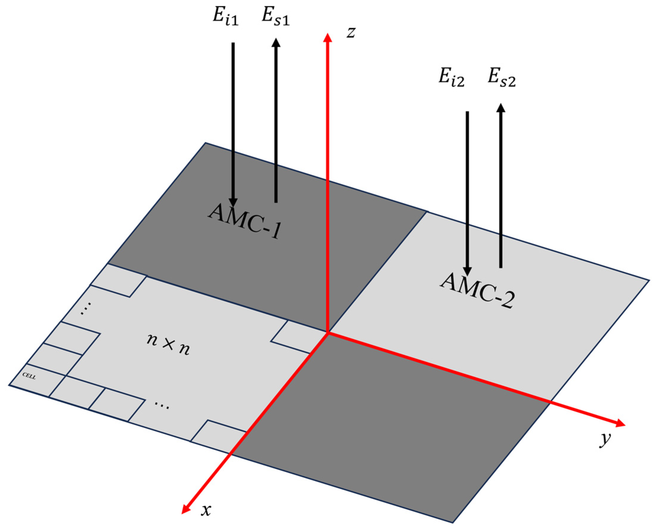
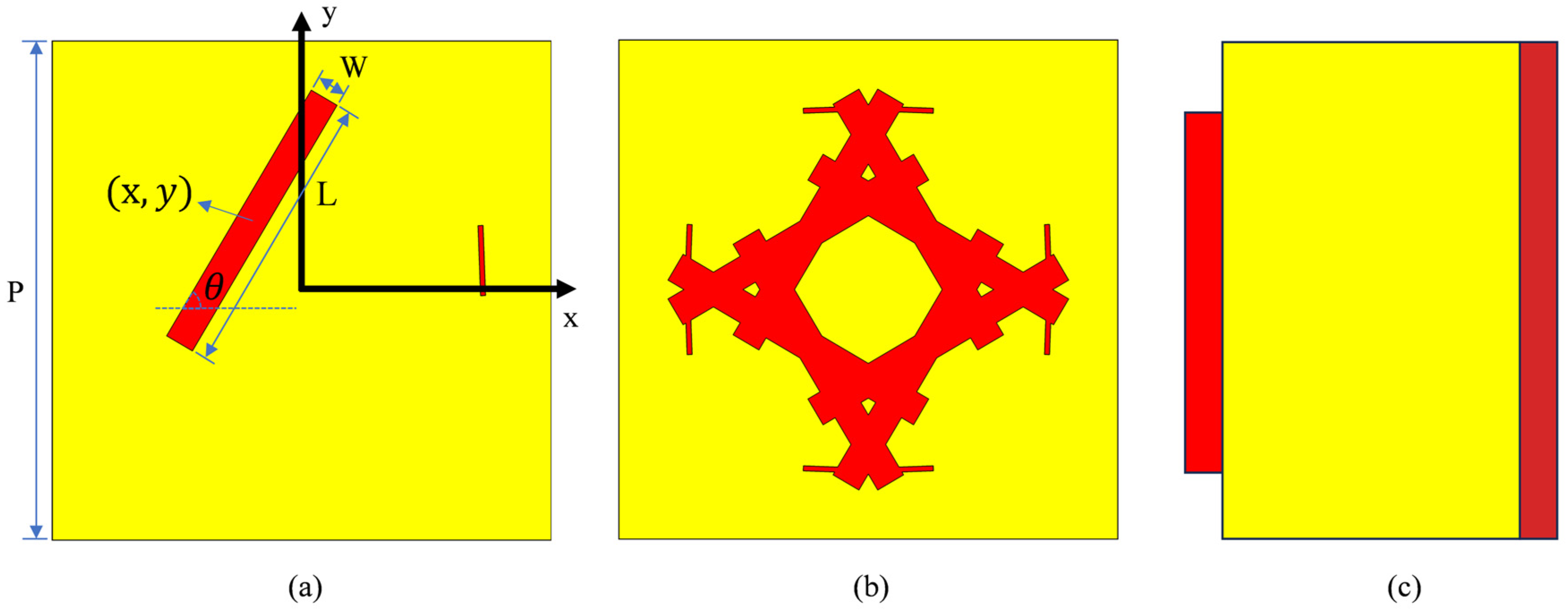
2.1. Design and Structures

As shown in Figure 1, a chessboard metasurface typically consists of alternating arrangements of the AMC1 block and AMC2 block, resembling a checkerboard pattern, with each block containing n × n unit cells. When a plane wave is incident upon this metasurface, the two types of AMC blocks exhibit different phase and amplitude responses to the incident wave:
E s 1 = A 1 E i 1 e j φ 1
E s 2 = A 2 E i 2 e j φ 2
where E s 1 and E s 2 , respectively, denote the electric fields of incident and reflected waves for AMC1 and AMC2 blocks, while φ n and A n represent the reflection phase and amplitude for the incident wave by both AMC types. By utilizing the definition of RCS, it is known that compared to a PEC with the same size (with a reflectivity of 1), the RCS reduction in dB can be calculated as follows [25]:
R C S     r e d u c t i o n = 10   log 10 l i m r [ 4 π r 2 E s 2 E i 2 ] l i m r [ 4 π r 2 ( 1 ) 2 ]
Considering the equal areas of both types of AMC, it is reasonable to assume that E i 1 = E i 2 . Additionally, due to the presence of the ground layer, it is evident that A n = 1 . By synthesizing the formulas mentioned above, the RCS reduction can be represented using φ 1 and φ 2 . To achieve a reduction greater than −10 dB, the following condition must be satisfied:
20   log 10 e j φ 1 + e j φ 2 2 < 10   d B
Solving the above equation, it becomes apparent that a phase difference ranging from 143° to 217° can result in an RCS reduction exceeding 10 dB. For simplicity and to ensure the effectiveness of the RCS reduction in practical applications, an effective phase difference of 180° ± 30° is adopted.
Due to the complex correlation between the phase response and geometric structure, it is challenging to define these relationships precisely. To achieve diverse reflect phase, we manipulate the geometrical structure of the metasurface using ten parameters.
During the parameterization process of AMC, a square canvas with dimensions of w × w, determined by the unit cell width, w, is initially prepared. On this canvas, two rectangular conductive elements, with predefined dimensions, center coordinates, and rotation angles, are positioned as depicted in Figure 2a. These rectangles are then symmetrically duplicated along the canvas’s diagonal, resulting in four identical rectangles. Subsequent symmetrical duplication along both the horizontal and vertical axes, with the canvas center as the reference point, yields a unit cell composed of 16 rectangular elements, as shown in Figure 2b, and the unit cells are constructed using an FR4 dielectric substrate, which possesses a thickness of 3 mm and a relative permittivity of 4.4 [26]. Governed by a set of 10 parameters, this methodology enables the sculpting of the unit cell’s geometry. Strategic operations such as symmetrical duplication facilitate the creation of unit cells with various configurations, thereby enabling diverse phase responses. Moreover, the unit cells generated by this method exhibit rotational symmetry (remaining identical upon a 90° rotation), thereby offering polarization insensitivity.

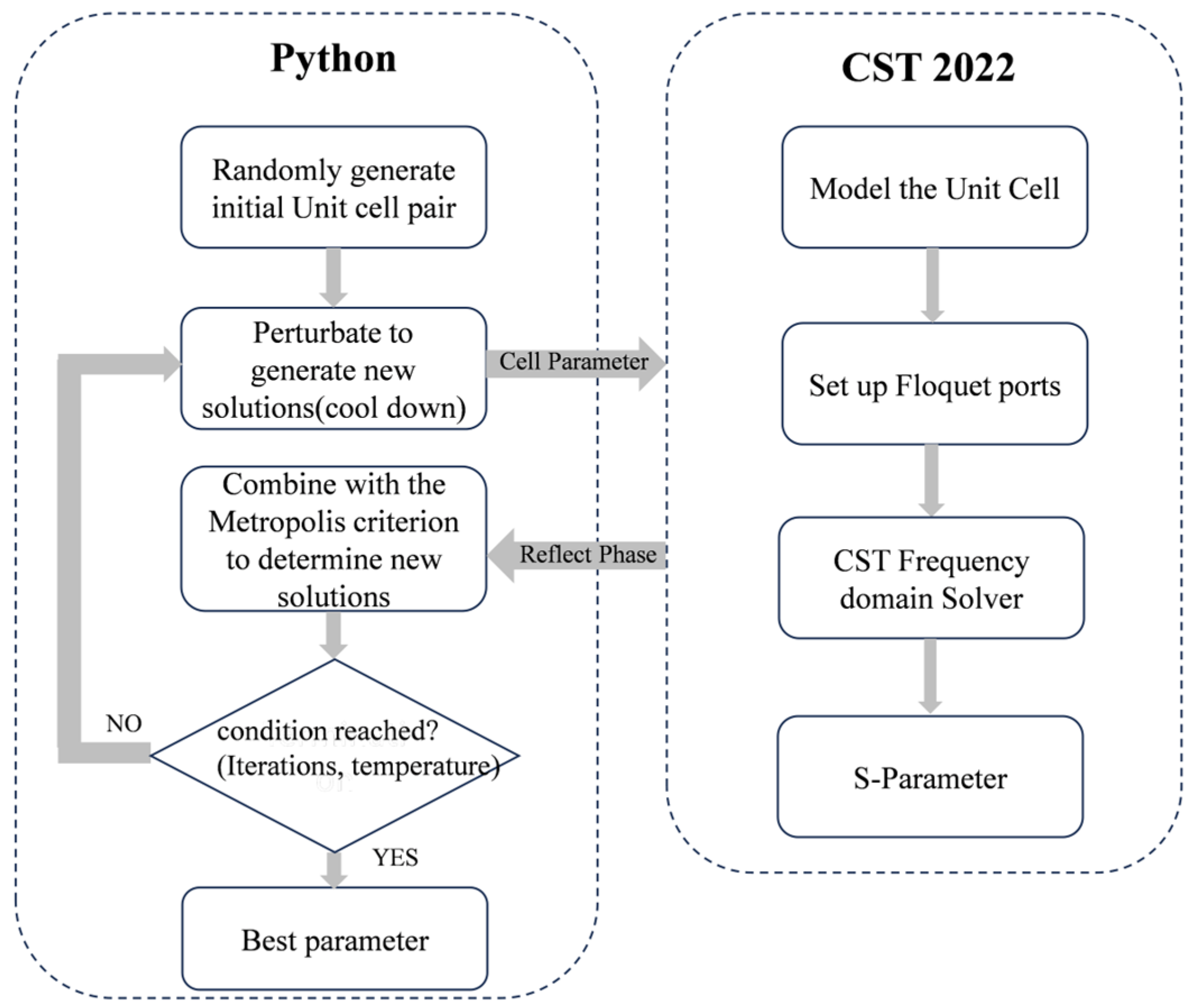
2.2. Parameter Optimization Process Using SA

The SA algorithm is inspired by the physical process of annealing in metallurgy [27], where a material is heated and then slowly cooled to reduce defects and achieve a low-energy crystalline state, which is more suitable for this type of single-objective continuous parameter optimization problem compared to algorithms like GA and PSO, since SA requires only one candidate solution evaluation per iteration (via perturbing the current solution), whereas GA and PSO typically evaluate a population of solutions (e.g., tens to hundreds of individuals) in each iteration [28,29,30]. For our problem, each evaluation involves a time-consuming CST simulation. SA’s single-evaluation-per-iteration strategy significantly reduces computational overhead. The key components of SA are as follows:
(1)
Objective Function (Energy Function):
The goal is to minimize the energy function E(x), where x represents the design parameters. In our work, the objective function of the SA is expressed as follows:
E x = i = 0 120 χ ϕ f i
χ ϕ = 1                 150 < ϕ < 210 0                                                       e l s e    
where ϕ is the phase difference between the two types of unit cells at the frequency point f i , and in this paper, the frequency range used is 6–18 GHz, with sampling intervals of 0.1 GHz. In addition, when the metal exceeds the design boundary, E ( x ) is assigned a value greater than 0, such as 100.
(2)
Perturbation Mechanism:
At each iteration, a small random perturbation is applied to the current parameters x.
r = U 1,1 10
x n e w = s i g n r T 1 + 1 T r 1 h o p + x c u r r e n t
(3)
Metropolis Criterion:
The perturbed solution x = x + δ x is accepted with probability:
P a c c e p t = 1                                                 i f   E x   E x   e E x E x T             o t h e r w i s e
This probabilistic acceptance allows the algorithm to explore suboptimal solutions early (high T ) and converge to minima as T 0 . This mechanism allows the algorithm to explore suboptimal solutions during the high-temperature phase and converge to the minimum value during the low-temperature phase.
(4)
Cooling Schedule:
The temperature T is reduced exponentially:
T k = T m a x e k e
To achieve accurate simulation results, the frequency-domain solver of CST is used and the Floquet boundaries are set along the x and y directions. The overall design process is shown in Figure 3 and Algorithm 1.
Algorithm 1 Simulated Annealing Algorithm for Metasurface
1: Input:
2: Objective function E(x),
3: Tmax = 1, Tmin = 1e − 6, L = 30, max_stay_counter = 30,
4: Upper bound ub, Lower bound lb
5: Output: Optimal solution xbest
6: Initialize:
7: TTmax
8: xcurrent ← rand(lb, ub) {Random initial solution within bounds}
9: EcurrentE(xcurrent)
10: xbestxcurrent
11: EbestEcurrent
12: stay_counter ← 0
13: k ← 1 {Iteration counter}
14: hopublb
15: while T > Tmin and stay_counter < max_stay_counter do
16:     for i = 1 to L do
17:      1. Perturbation Mechanism
18:      rU (−1, 1)d
19:      xc s i g n r T 1 + 1 T r 1
20:      xnewxcurrent + xc × hop
21:      if HasBounds then
22:       xnew ← clamp(xnew, lb, ub)
23:      end if
24:      2. Energy evaluation
25:      if xnew violates design boundaries then
26:       Enew ← 100
27:      else
28:       EnewE(xnew)
29:      end if
30:      3. Metropolis Criterion
31:      if Enew < Ecurrent or exp (− E n e w E c u r r e n t T )) > rand then
32:       xcurrentxnew
33:       EcurrentEnew
34:       if Enew < Ebest then
35:        xbestxnew
36:        EbestEnew
37:       end if
38:      end if
39:     end for
40:     4. Cooling Schedule
41:     TTmax × exp(− k e )
42:     k ← k + 1
43:     if Ebest unchanged then
44:stay_counterstay_counter + 1
45:     else
46:    stay_counter ← 0
47:     end if
48: end while
49: return xbes

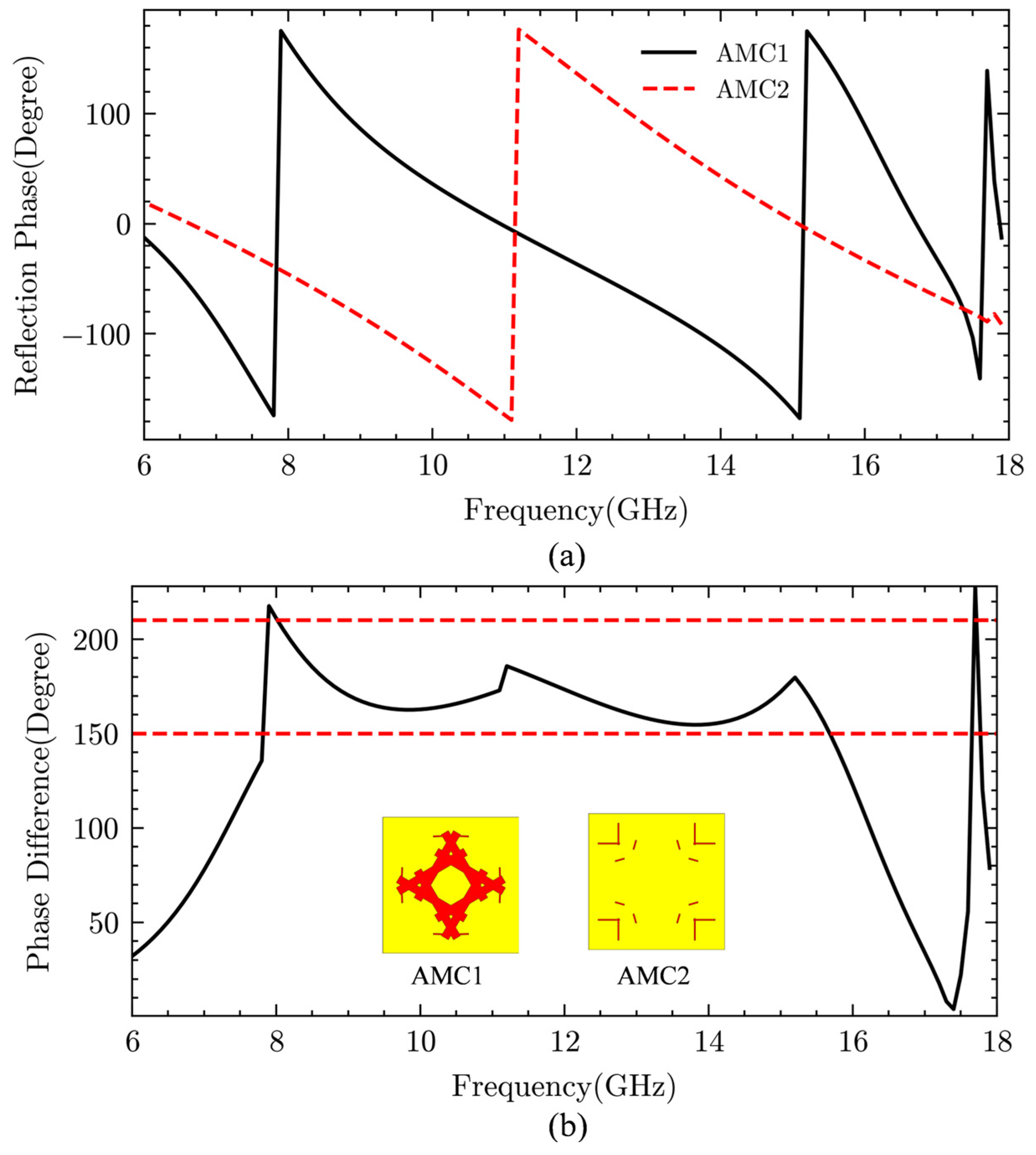
2.3. Optimized Results of Unit Cells

After the SA process, a set of optimized solutions with a bandwidth of 7.6 GHz (as shown in Table 1) was selected for a chessboard metasurface to validate the effectiveness of this SA-based method. The reflection phases and phase differences in the two unit cells are shown in Figure 4. Each AMC is composed of 7 × 7 cells, and the proposed metasurface consists of 4 × 4 AMC blocks. The total size of the designed chessboard metasurface is 280 mm × 280 mm × 3 mm. The RCS of the aforementioned metasurface was simulated using the time-domain solver of CST (based on the Finite Integration Technique), and the fabricated metasurface and overall structure are shown in Figure 5. To gain deeper physical understanding, we examine the distributions of surface currents at the zero reflection phase frequency point of unit cell #1’s upper and ground layers. As shown in Figure 6, at 5.77 GHz, the antiparallel surface currents create a magnetic resonance. At 10.94 and 16.7 GHz, the central part of the unit cell exhibits currents in the opposite direction to those on the ground, forming magnetic resonances, while the peripheral parts have currents moving in the same direction as the ground, forming electric resonances. Together, these multiple resonances result in several zero-phase reflection points within the 8–17 GHz frequency range.

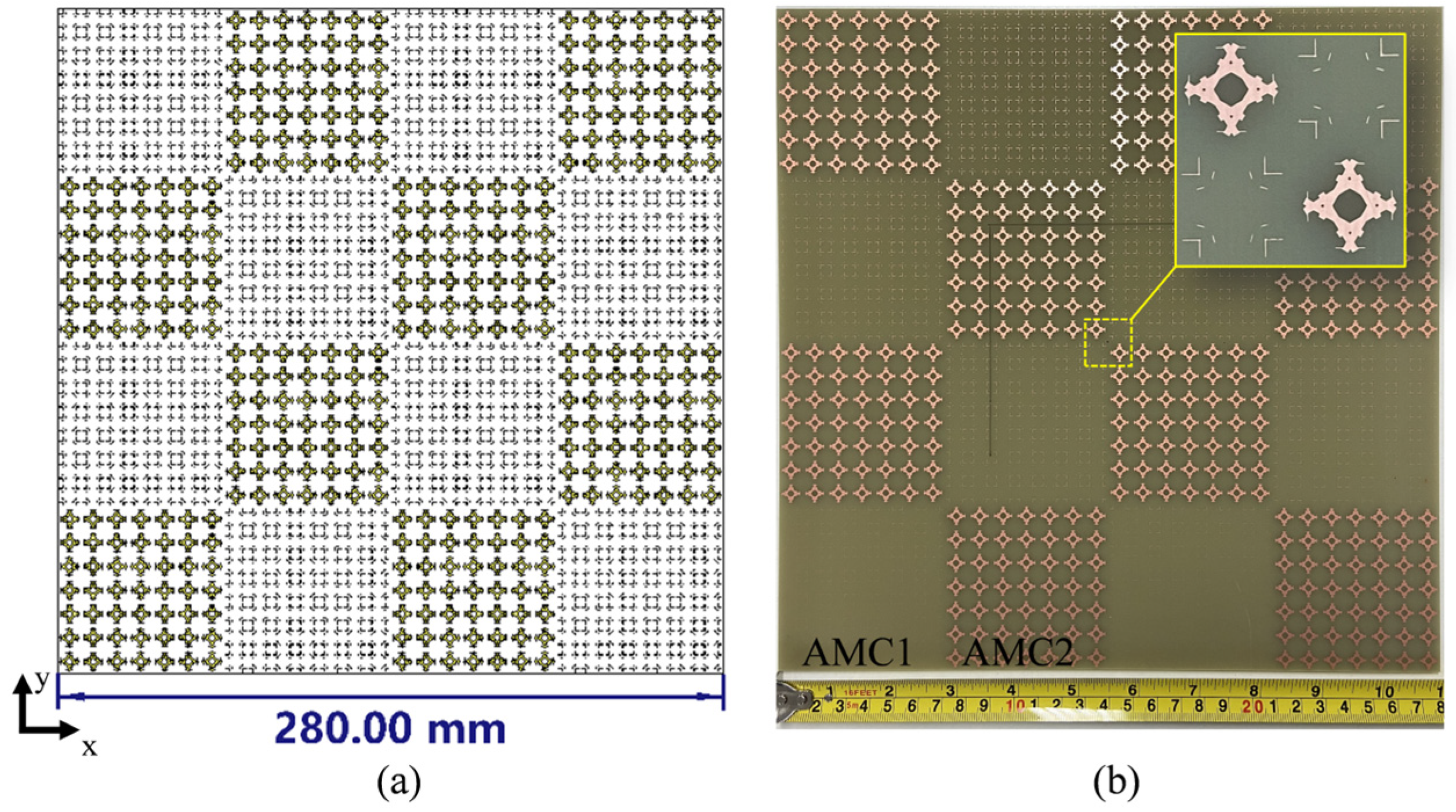
3. Experiment Results

The architecture of the measurement setup is illustrated in Figure 7, comprising two horn antennas operating in the 2–18 GHz frequency range connected to a Vector Network Analyzer (VNA) and aligned with the center of the metasurface. Additionally, a PEC plane with the same dimensions as the chessboard metasurface is fabricated to serve as a reference. Using the aforementioned system, the transmission coefficients of the PEC and chessboard metasurface are measured separately. By subtracting one from the other, the RCS reduction can be obtained.

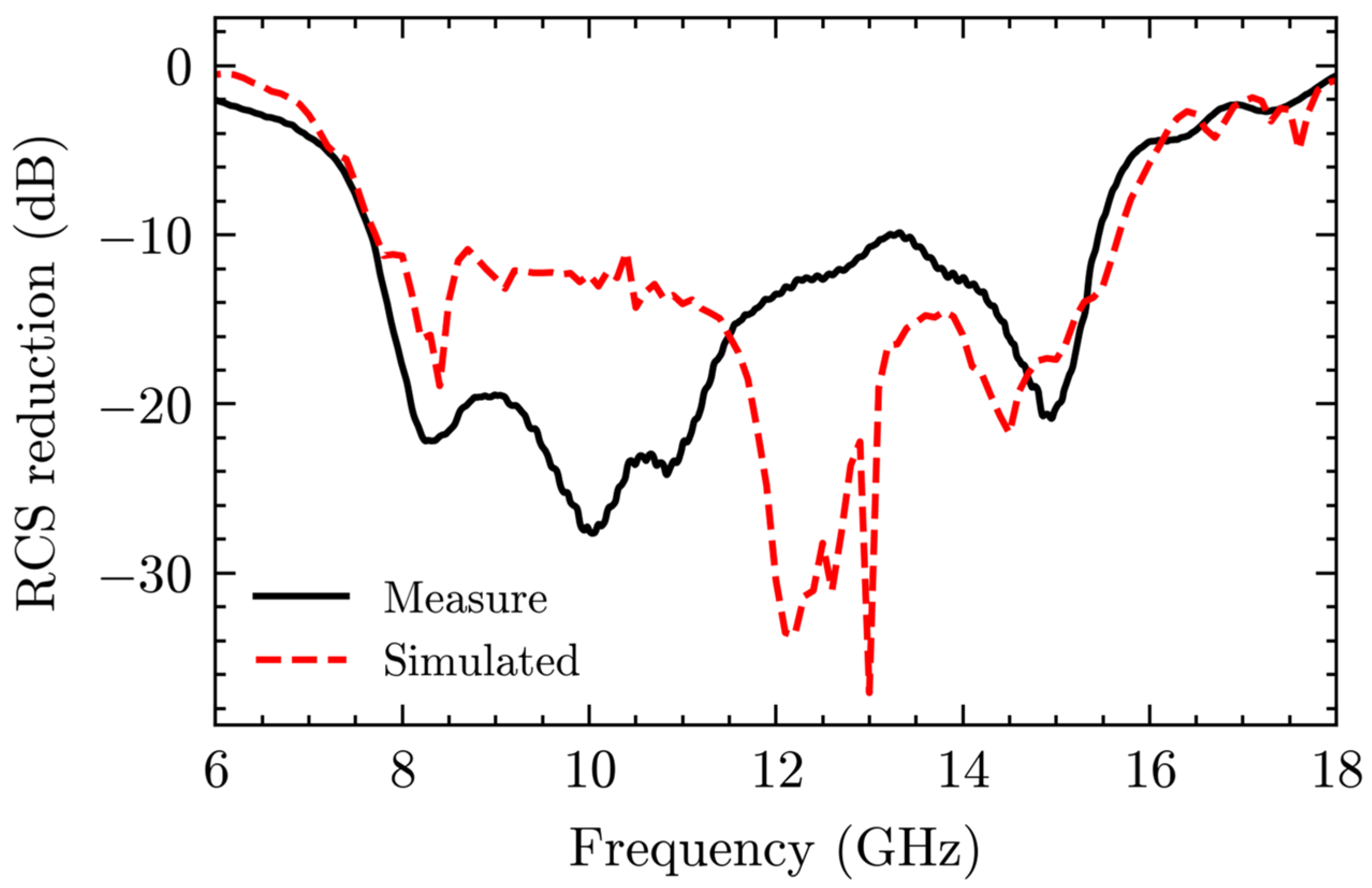
3.1. Monostatic Results

As shown in Figure 8, it should be noted that the measured 10 dB RCS reduction bandwidth is from 7.6 to 15.5 GHz, which closely matches the simulated bandwidth of 7.6 to 15.7 GHz obtained from RCS simulations (x-polarization). Moreover, this is in agreement with the phase difference simulations of the unit cell pair within the 180 ± 30° frequency band. Within this frequency band, the maximum attenuation was observed to be −28 dB at 10 GHz, with the RCS also reaching −20 dB at 15.1 GHz. Additionally, for oblique incidence, the monostatic RCS reduction, as shown in Figure 9, demonstrates that this metasurface maintains a stable reduction effect for incident angles ranging from 0 to 30 degrees. It can be observed that the deviation between the measured and simulated results may be attributed to the fabrication process of the proposed cell pair, which involves several rectangles with a width of 0.1 mm, which are sensitive to manufacturing tolerances. Slight misalignments or edge roughness during fabrication (Figure 5b) can alter the resonance behavior, leading to frequency shifts and amplitude variations.

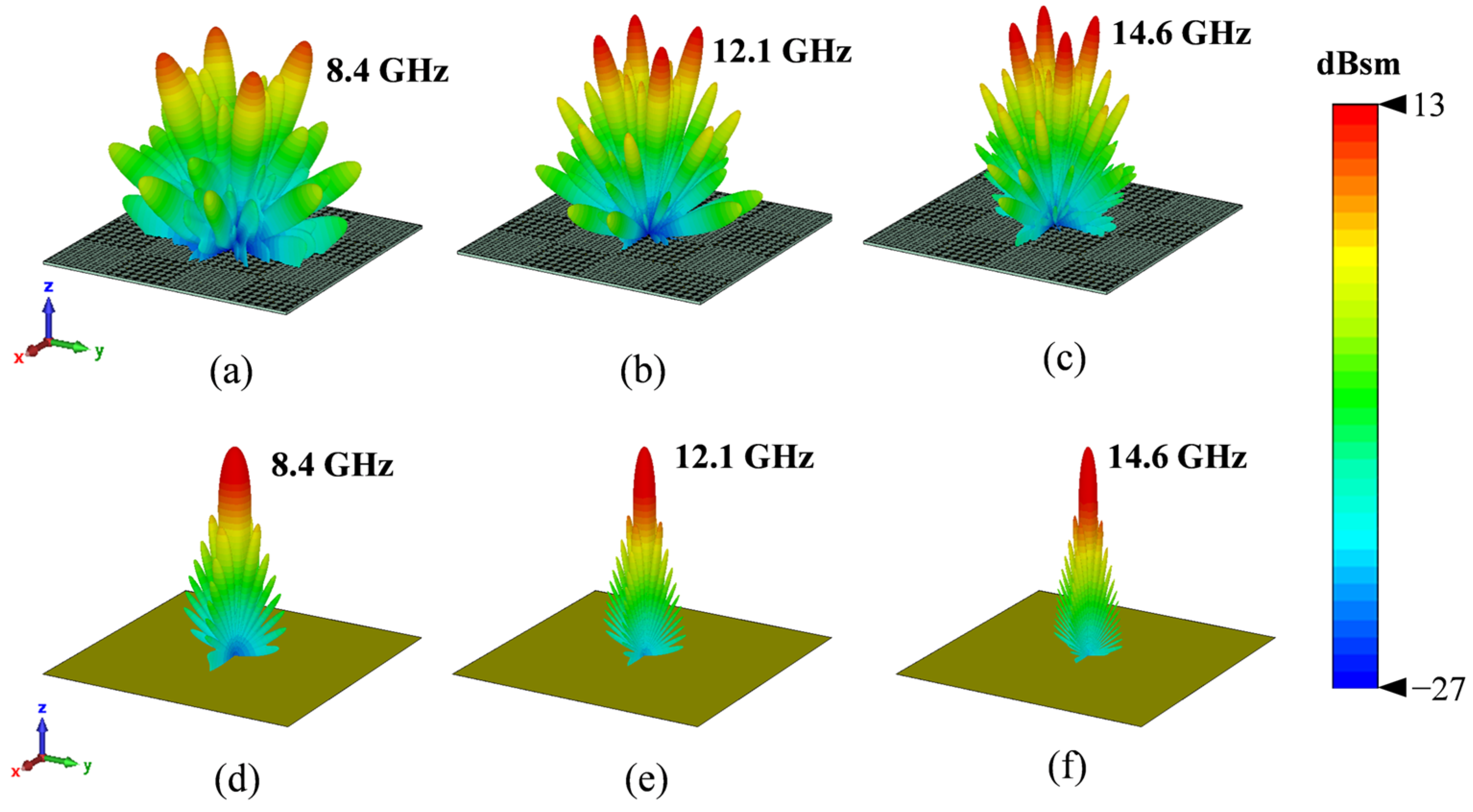
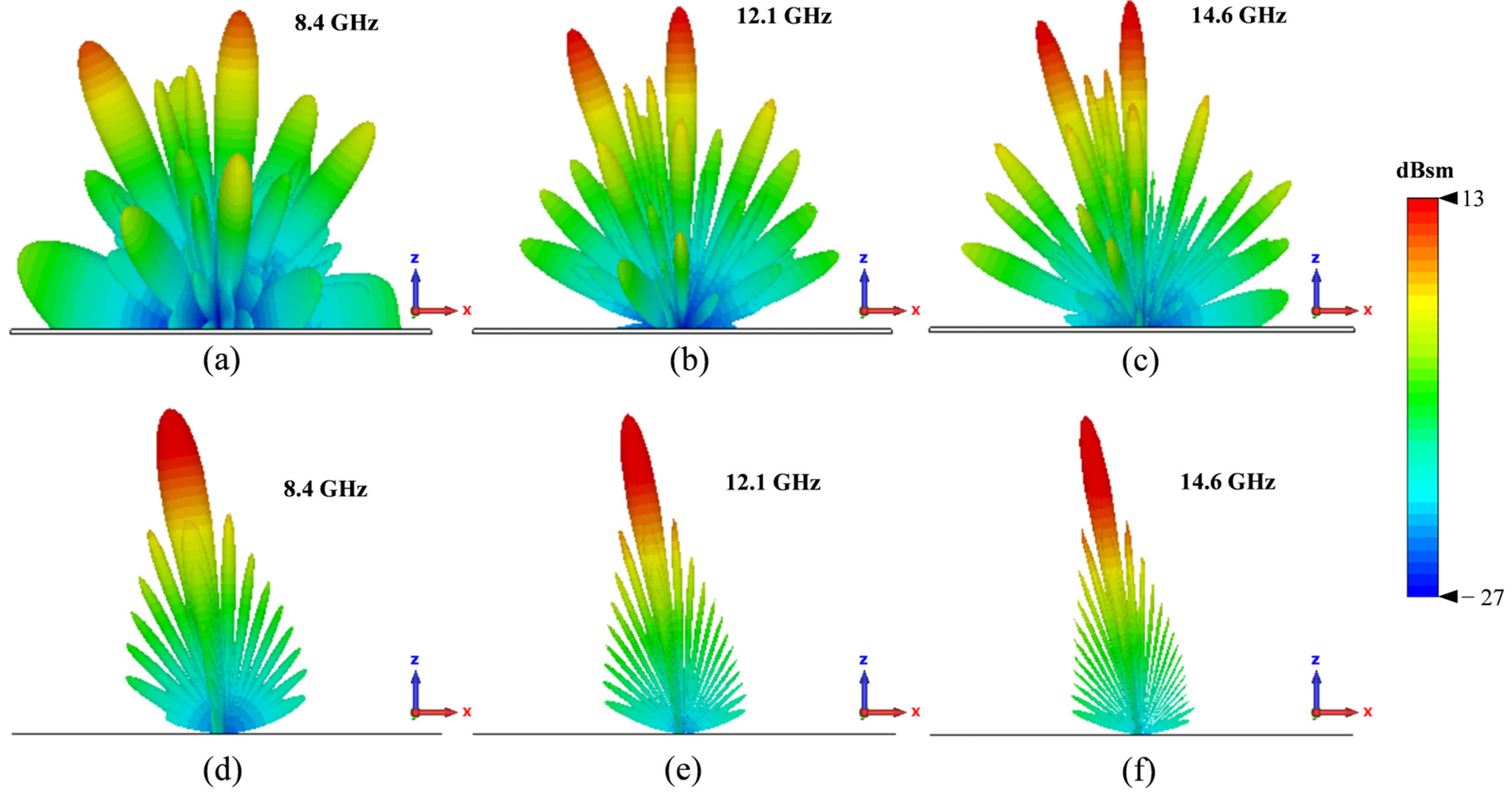
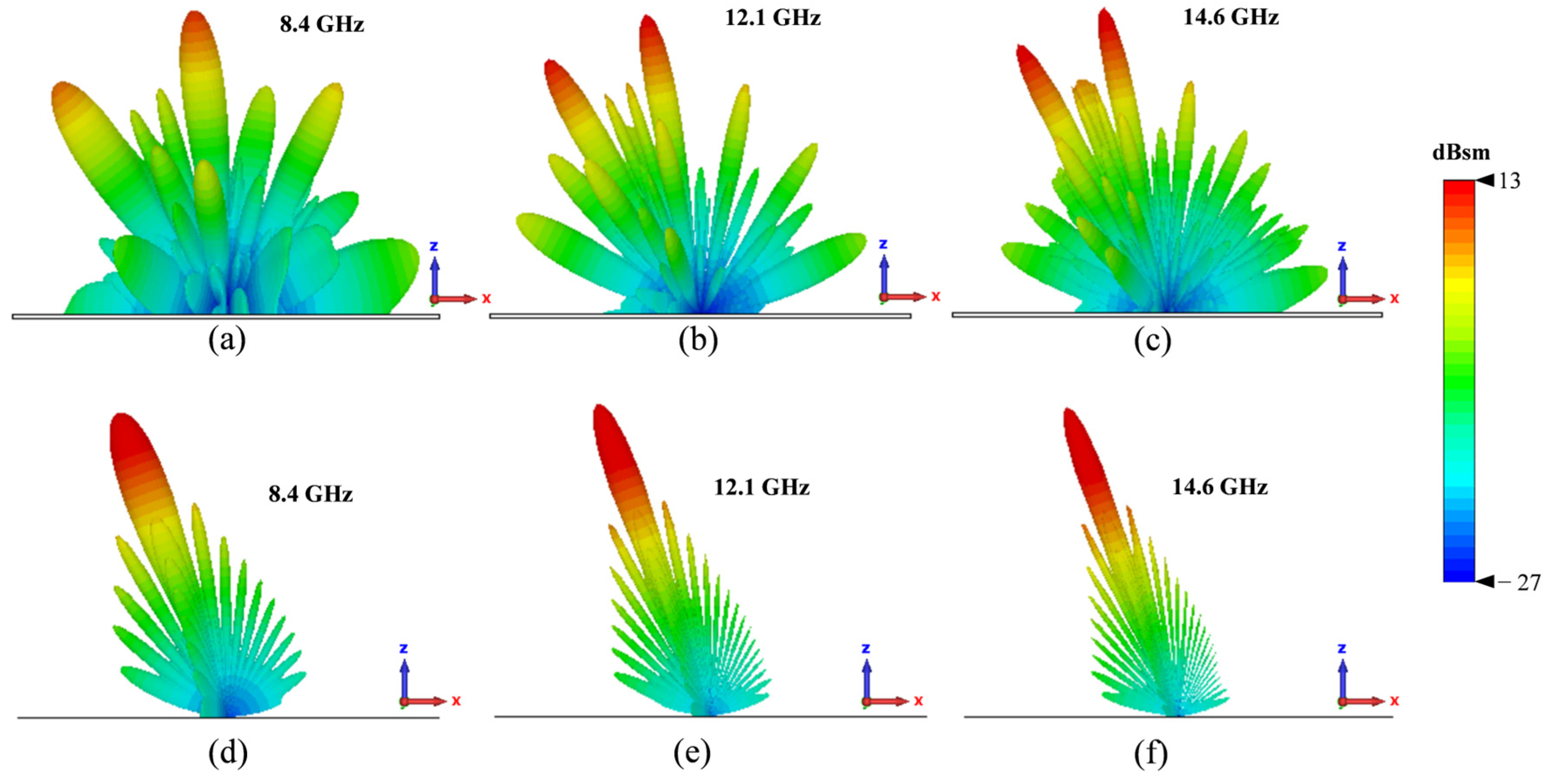
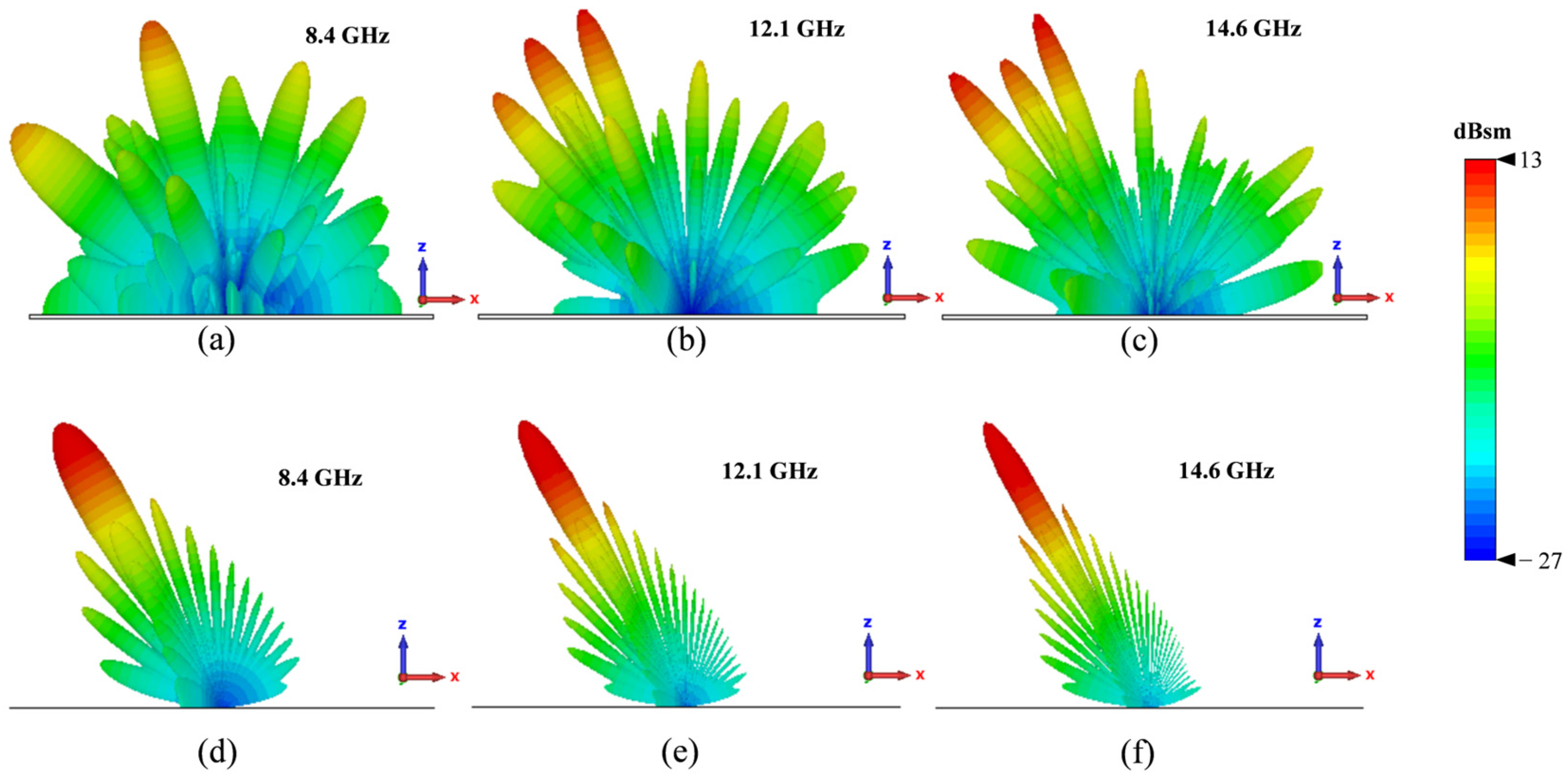
3.2. Bistatic Results

Figure 10 illustrates the bistatic 3D RCS patterns for both the chessboard metasurface and a PEC surface of the same size at frequencies of 8, 10, and 12 GHz, with incident waves striking the surface perpendicularly (normal incidence). At these frequencies, the PEC surface reflects nearly all incident waves back in the direction of incidence. In contrast, the proposed metasurface reflects the waves predominantly into four distinct directions, forming four lobes, none of which align with the normal direction, This phenomenon can be explained by the generalized Snell’s law [11]: the metasurface generates a phase gradient in multiple directions within the xy-plane, causing the reflected waves to deviate from the principal axis. This observation is consistent with the findings in [31]. In addition, we also simulated the 3D RCS patterns at incident angles of 10 degrees, 20 degrees, and 30 degrees (Figure 11, Figure 12 and Figure 13).
Table 2 shows a comparison of the performance metrics of the proposed metasurface against those of other published works. This comparison highlights that the proposed metasurface not only exhibits superior performance in the 10 dB RCS reduction band but also demonstrates outstanding performance in the oblique incident angle.

4. Conclusions

In this work, a novel approach for the inverse design of metasurface unit cells aimed at achieving RCS reduction was proposed. Instead of relying on a matrix or pixel-based representation, we modelled the unit cells using a limited set of parameters combined with rotational symmetry. This strategy allowed us to achieve a broader range of structural designs without the requirement for extensive data. Additionally, by optimizing the phase difference between the parameterized unit cells using an SA algorithm, we successfully achieved broadband RCS reduction. The optimized unit cell pair demonstrated a 10 dB reduction in RCS over the 7.6–15.5 GHz frequency range with excellent angular stability. The adaptability of this method enables optimization across arbitrary frequency bands by adjusting the substrate thickness and unit cell period. While the method’s computational cost and fabrication constraints present challenges, the approach can be extended to design other types of metasurfaces, such as PGMs and PVMs, by incorporating different objective functions and rotational symmetry strategies.

Author Contributions

Conceptualization, H.X.; methodology, H.X.; software, H.X. writing—original draft preparation, H.X.; validation, X.L.; formal analysis, B.J.; investigation, P.S.; data curation, Z.C.; supervision, N.X.; writing—review and editing, S.P.; All authors have read and agreed to the published version of the manuscript.

Funding

This research was supported in part by the National Science and Technology Major Project, grant number 2021ZD0114600; the Fundamental Research Funds for the Central Universities, grant number 2024-LXY-B1-01; the National Natural Science Foundation of China, grant number 62104174; and partly by the National Innovation & Entrepreneurship Training Program for College Students, grant number 20240100435.

Institutional Review Board Statement

Not applicable.

Informed Consent Statement

Not applicable.

Data Availability Statement

The original contributions presented in the study are included in the article, further inquiries can be directed to the corresponding author.

Conflicts of Interest

The authors declare no conflict of interest.

References

  1. Shin, H.; Yoon, D.; Kim, C.; Yang, Y.S.; Lee, M.G.; Park, J.Y.; Hwang, K.C.; Park, Y.B. Shape Optimization of an Integrated Mast for RCS Reduction of a Stealth Naval Vessel. Appl. Sci. 2021, 11, 2819. [Google Scholar] [CrossRef]
  2. Feng, J.; Zong, Y.; Sun, Y.; Zhang, Y.; Yang, X.; Long, G.; Wang, Y.; Li, X.; Zheng, X. Optimization of Porous FeNi3/N-GN Composites with Superior Microwave Absorption Performance. Chem. Eng. J. 2018, 345, 441–451. [Google Scholar] [CrossRef]
  3. Breiss, H.; El Assal, A.; Benzerga, R.; Sharaiha, A.; Jrad, A.; Harmouch, A. Ultra-Porous and Lightweight Microwave Absorber Based on Epoxy Foam Loaded with Long Carbon Fibers. Mater. Res. Bull. 2021, 137, 111188. [Google Scholar] [CrossRef]
  4. Pozar, D.M. RCS Reduction for a Microstrip Antenna Using a Normally Biased Ferrite Substrate. IEEE Microw. Guid. Wave Lett. 1992, 2, 196–198. [Google Scholar] [CrossRef]
  5. Hou, H.; Long, J.; Wang, J.; Sievenpiper, D.F. Reduced Electromagnetic Edge Scattering Using Inhomogeneous Anisotropic Impedance Surfaces. IEEE Trans. Antennas Propag. 2017, 65, 1193–1201. [Google Scholar] [CrossRef]
  6. Knott, E.B.; Shaeffer, J.F.; Tully, M.T. Radar Cross Section; Scitech Publishing, Cop.: Raleigh, NC, USA, 2004; ISBN 9781891121258. [Google Scholar]
  7. Gao, X.; Han, X.; Cao, W.P.; Li, H.O.; Ma, H.F.; Cui, T.J. Ultrawideband and High-Efficiency Linear Polarization Converter Based on Double V-Shaped Metasurface. IEEE Trans. Antennas Propag. 2015, 63, 3522–3530. [Google Scholar] [CrossRef]
  8. Fu, C.; Han, L.; Liu, C.; Sun, Z.; Lu, X. Dual-Band Polarization Conversion Metasurface for RCS Reduction. IEEE Trans. Antennas Propag. 2021, 69, 3044–3049. [Google Scholar] [CrossRef]
  9. Lu, Y.; Su, J.; Liu, J.; Guo, Q.; Yin, H.; Li, Z.; Song, J. Ultrawideband Monostatic and Bistatic RCS Reductions for Both Copolarization and Cross Polarization Based on Polarization Conversion and Destructive Interference. IEEE Trans. Antennas Propag. 2019, 67, 4936–4941. [Google Scholar] [CrossRef]
  10. Li, X.; Wang, Y.; Fan, J.; He, J.; Huang, X. Ultra-Thin/Wide-Band Polarization Conversion Metasurface and Its Applications in Anomalous Reflection and RCS Reduction. Appl. Sci. 2022, 12, 7696. [Google Scholar] [CrossRef]
  11. Yu, N.; Genevet, P.; Kats, M.A.; Aieta, F.; Tetienne, J.-P.; Capasso, F.; Gaburro, Z. Light Propagation with Phase Discontinuities: Generalized Laws of Reflection and Refraction. Science 2011, 334, 333–337. [Google Scholar] [CrossRef]
  12. Yuan, F.; Wang, G.-M.; Xu, H.-X.; Cai, T.; Zou, X.-J.; Pang, Z.-H. Broadband RCS Reduction Based on Spiral-Coded Metasurface. IEEE Antennas Wirel. Propag. Lett. 2017, 16, 3188–3191. [Google Scholar] [CrossRef]
  13. Li, Y.; Cao, Q.; Wang, Y. Radar Cross Section Reduction Metasurfaces Based on Phase Gradient and Chessboard Structure. Int. J. RF Microw. Comput.-Aided Eng. 2018, 28, e21457. [Google Scholar] [CrossRef]
  14. Su, J.; Li, W.; Qu, M.; Yu, H.; Li, Z.; Qi, K.; Yin, H. Ultrawideband RCS Reduction Metasurface Based on Hybrid Mechanism of Absorption and Phase Cancellation. IEEE Trans. Antennas Propag. 2022, 70, 9415–9424. [Google Scholar] [CrossRef]
  15. Yang, J.J.; Cheng, Y.Z.; Qi, D.; Gong, R.Z. Study of Energy Scattering Relation and RCS Reduction Characteristic of Matrix-Type Coding Metasurface. Appl. Sci. 2018, 8, 1231. [Google Scholar] [CrossRef]
  16. Zheng, Y.; Gao, J.; Cao, X.; Yuan, Z.; Yang, H. Wideband RCS Reduction of a Microstrip Antenna Using Artificial Magnetic Conductor Structures. IEEE Antennas Wirel. Propag. Lett. 2015, 14, 1582–1585. [Google Scholar] [CrossRef]
  17. Su, J.; Lu, Y.; Liu, J.; Yang, Y.; Li, Z.; Song, J. A Novel Checkerboard Metasurface Based on Optimized Multielement Phase Cancellation for Superwideband RCS Reduction. IEEE Trans. Antennas Propag. 2018, 66, 7091–7099. [Google Scholar] [CrossRef]
  18. Modi, A.Y.; Balanis, C.A.; Birtcher, C.R.; Shaman, H.N. Novel Design of Ultrabroadband Radar Cross Section Reduction Surfaces Using Artificial Magnetic Conductors. IEEE Trans. Antennas Propag. 2017, 65, 5406–5417. [Google Scholar] [CrossRef]
  19. Qiu, T.; Shi, X.; Wang, J.; Li, Y.; Qu, S.; Cheng, Q.; Cui, T.; Sui, S. Deep Learning: A Rapid and Efficient Route to Automatic Metasurface Design. Adv. Sci. 2019, 6, 1900128. [Google Scholar] [CrossRef]
  20. Gosal, G.; Almajali, E.; McNamara, D.; Yagoub, M. Transmitarray Antenna Design Using Forward and Inverse Neural Network Modeling. IEEE Antennas Wirel. Propag. Lett. 2016, 15, 1483–1486. [Google Scholar] [CrossRef]
  21. An, S.; Zheng, B.; Tang, H.; Shalaginov, M.Y.; Zhou, L.; Li, H.; Kang, M.; Richardson, K.A.; Gu, T.; Hu, J.; et al. Multifunctional Metasurface Design with a Generative Adversarial Network. Adv. Opt. Mater. 2021, 9, 2001433. [Google Scholar] [CrossRef]
  22. Liu, Z.; Zhu, D.; Rodrigues, S.P.; Lee, K.-T.; Cai, W. Generative Model for the Inverse Design of Metasurfaces. Nano Lett. 2018, 18, 6570–6576. [Google Scholar] [CrossRef] [PubMed]
  23. You, X.C.; Lin, F.H. Inverse Design of Reflective Metasurface Antennas Using Deep Learning from Small-Scale Statistically Random Pico-Cells. Microw. Opt. Technol. Lett. 2024, 66, e34068. [Google Scholar] [CrossRef]
  24. Naseri, P.; Hum, S.V. A Generative Machine Learning-Based Approach for Inverse Design of Multilayer Metasurfaces. IEEE Trans. Antennas Propag. 2021, 69, 5725–5739. [Google Scholar] [CrossRef]
  25. Yao, P.; Zhang, B.; Duan, J. A Broadband Artificial Magnetic Conductor Reflecting Screen and Application in Microstrip Antenna for Radar Cross-Section Reduction. IEEE Antennas Wirel. Propag. Lett. 2018, 17, 405–409. [Google Scholar] [CrossRef]
  26. Aguilar, J.R.; Beadle, M.; Thompson, P.T.; Shelley, M.W. The Microwave and RF Characteristics of FR4 Substrates. In Proceedings of the IEE Colloquium on Low Cost Antenna Technology, London, UK, 24 February 1998. [Google Scholar] [CrossRef]
  27. Kirkpatrick, S.; Gelatt, C.D.; Vecchi, M.P. Optimization by Simulated Annealing. Science 1983, 220, 671–680. [Google Scholar] [CrossRef]
  28. Eberhart, R.C.; Shi, Y.; Kennedy, J. Swarm Intelligence; Elsevier: Amsterdam, The Netherlands, 2001; ISBN 9780080518268. [Google Scholar]
  29. Goldberg, D.E. Genetic Algorithms in Search, Optimization, and Machine Learning; Addison-Wesley Professional: Reading, MA, USA, 1989. [Google Scholar]
  30. Eberhart; Shi, Y. Particle Swarm Optimization: Developments, Applications and Resources. In Proceedings of the 2001 Congress on Evolutionary Computation, Seoul, Republic of Korea, 27–30 May 2001; Available online: https://ieeexplore.ieee.org/abstract/document/934374 (accessed on 7 August 2002).
  31. Iriarte Galarregui, J.C.; Tellechea Pereda, A.; de Falcon, J.L.M.; Ederra, I.; Gonzalo, R.; de Maagt, P. Broadband Radar Cross-Section Reduction Using AMC Technology. IEEE Trans. Antennas Propag. 2013, 61, 6136–6143. [Google Scholar] [CrossRef]
  32. Chen, W.; Balanis, C.A.; Birtcher, C.R. Checkerboard EBG Surfaces for Wideband Radar Cross Section Reduction. IEEE Trans. Antennas Propag. 2015, 63, 2636–2645. [Google Scholar] [CrossRef]
  33. Pang, X.; Zhang, T.; Hu, M.; Zhang, H.; Zheng, Q. Broadband Low-Scattering and High-Efficiency Transmission Radome by Combing Phase Gradient Metasurface and FSS. Opt. Commun. 2024, 563, 130598. [Google Scholar] [CrossRef]
  34. El-Sewedy, M.F.; Abdalla, M.A. A Monostatic and Bistatic RCS Reduction Using Artificial Magnetic Conductor Metasurface. IEEE Trans. Antennas Propag. 2022, 71, 1988–1992. [Google Scholar] [CrossRef]
  35. Ji, K.F.; Gao, J.; Cao, X.; Han, J.; Yang, H. Design of Ultra-Wideband Low RCS Reflecting Screen Based on Phase Gradient Metasurface. Radioengineering 2021, 30, 314–322. [Google Scholar] [CrossRef]
  36. Yuan, F.; Xu, H.-X.; Jia, X.-Q.; Wang, G.-M.; Fu, Y. RCS Reduction Based on Concave/Convex-Chessboard Random Parabolic-Phased Metasurface. IEEE Trans. Antennas Propag. 2020, 68, 2463–2468. [Google Scholar] [CrossRef]
  37. Liu, X.; Gao, J.; Xu, L.; Cao, X.; Zhao, Y.; Li, S. A Coding Diffuse Metasurface for RCS Reduction. IEEE Antennas Wirel. Propag. Lett. 2017, 16, 724–727. [Google Scholar] [CrossRef]
  38. Han, J.; Cao, X.; Gao, J.; Wei, J.; Zhao, Y.; Li, S.; Zhang, Z. Broadband Radar Cross Section Reduction Using Dual-Circular Polarization Diffusion Metasurface. IEEE Antennas Wirel. Propag. Lett. 2018, 17, 969–973. [Google Scholar] [CrossRef]
Figure 1. AMC chessboard metasurface configuration.
Applsci 15 02883 g001
Figure 2. The unit cell structure. (a) The original structure. (b) The structure after rotational symmetry. (c) The side view.
Applsci 15 02883 g002
Figure 3. Flowchart of cell pair optimization.
Applsci 15 02883 g003
Figure 4. (a) The reflection phase of the unit cell. (b) The phase difference between two cells.
Applsci 15 02883 g004
Figure 5. Top view of proposed chessboard metasurface: (a) design layout; (b) physical layout.
Applsci 15 02883 g005
Figure 6. Surface current distribution of upper and ground layers at 5.77, 10.94, and 16.7 GHz, where arrows imply current flow direction. (ac) Upper layer; (df) ground layer.
Applsci 15 02883 g006
Figure 7. (a) Measurement system schematic. (b) Measuring system equipment.
Applsci 15 02883 g007
Figure 8. Simulated and measured monostatic RCS.
Applsci 15 02883 g008
Figure 9. Simulated monostatic results in oblique incident.
Applsci 15 02883 g009
Figure 10. Simulated 3D RCS patterns of metasurface and PEC at 8.4, 12.1, and 14.6 GHz. (ac) Chessboard metasurface. (df) PEC surface.
Applsci 15 02883 g010
Figure 11. Simulated 3D RCS patterns of metasurface and PEC at 8.4, 12.1, and 14.6 GHz with incident angle of 10 degrees. (ac) Chessboard metasurface. (df) PEC surface.
Applsci 15 02883 g011
Figure 12. Simulated 3D RCS patterns of metasurface and PEC at 8.4, 12.1, and 14.6 GHz with incident angle of 20 degrees. (ac) Chessboard metasurface. (df) PEC surface.
Applsci 15 02883 g012
Figure 13. Simulated 3D RCS patterns of metasurface and PEC at 8.4, 12.1, and 14.6 GHz with incident angle of 30 degrees. (ac) Chessboard metasurface. (df) PEC surface.
Applsci 15 02883 g013
Table 1. Geometry parameter of optimized cell pair.
x (mm)y (mm)W (mm)L (mm)Theta (Degree)
Cell#1Rec#1−1.0−1.40.65.730.5
Rec#23.6−0.61.40.187.9
Cell#2Rec#1−2.7−1.60.70.1−16
Rec#22.8−3.51.60.190
Table 2. Comparison between other work ( λ 0 : wavelength corresponding to center frequency of 10 dB reduction band, F o M = B W N o r m a l   + B W 30 °   S u b s t r a t e   T h i c k n e s s   N u n i t   c e l l ).
Ref.10 dB RCS Reduction BW (GHz, %)10 dB RCS Reduction BW (GHz, %) of 30° Incidence AngleSubstrate ThicknessNumber of Unit Cells, Period (mm)Figure of Merit (FoM)Strategy
[31]14.7–22.6/42.3%16.6–20.4/20.5% 0.08 λ 0 2, p = 43.90/ λ 0 Phase Difference
[32]4.2–7.8/60%5.1–6.7/27.1% 0.13 λ 0 2, p = 153.34/ λ 0 Phase Difference
[33]7.9–18.2/78%/ 0.13 λ 0 6, p = 8/Phase Gradient
[34]23.7–33.5/34%/ 0.08 λ 0 2, p = 5.8/Phase Difference
[35]10.8–15.3/34%9.3–13.7/38.3% 0.13 λ 0 6, p = 100.92/ λ 0 Phase Gradient
[36]7.8–23.2/102.7%7.1–22.4/103.7% 0.16 λ 0 10, p = 91.28/ λ 0 Phase Difference
[37]5.4–7.4/31.3%5.7–6.4/29.7%0.06 λ 0 5, p = 22.03/ λ 0 Phase Gradient
[38]10–20.7/69.7%/0.15 λ 0 4, p = 7/Polarization rotation
This work7.6–15.5/68.3%7.8–14.6/61% 0.11 λ 0 2, p = 105.8/ λ 0 Phase Difference
Disclaimer/Publisher’s Note: The statements, opinions and data contained in all publications are solely those of the individual author(s) and contributor(s) and not of MDPI and/or the editor(s). MDPI and/or the editor(s) disclaim responsibility for any injury to people or property resulting from any ideas, methods, instructions or products referred to in the content.

