
Eco-Friendly Metadome-Antenna Innovations for Wearable Millimeter Wave Radar Sensing


Abstract
Featured Application
Abstract
1. Introduction
2. Materials and Methods
2.1. Eco-Friendly Materials Used for the Antenna and the Metasurface
2.1.1. Eco-Friendly Dielectric Substrate: Polypropylene (PP)
2.1.2. Eco-Friendly Conductor: Aluminum (Al)
2.2. Design of the Metasurface-Based Radome
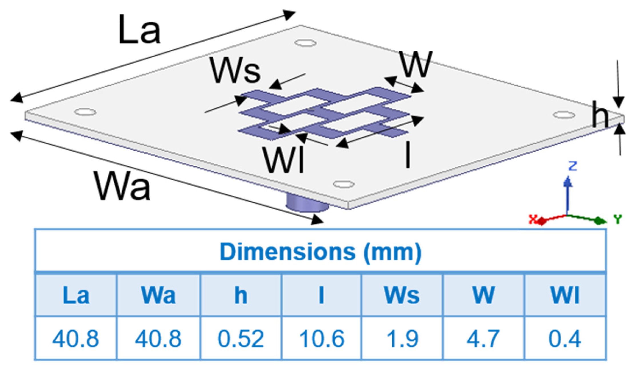
2.3. Design of the Grid Array Antenna for Radar Sensing
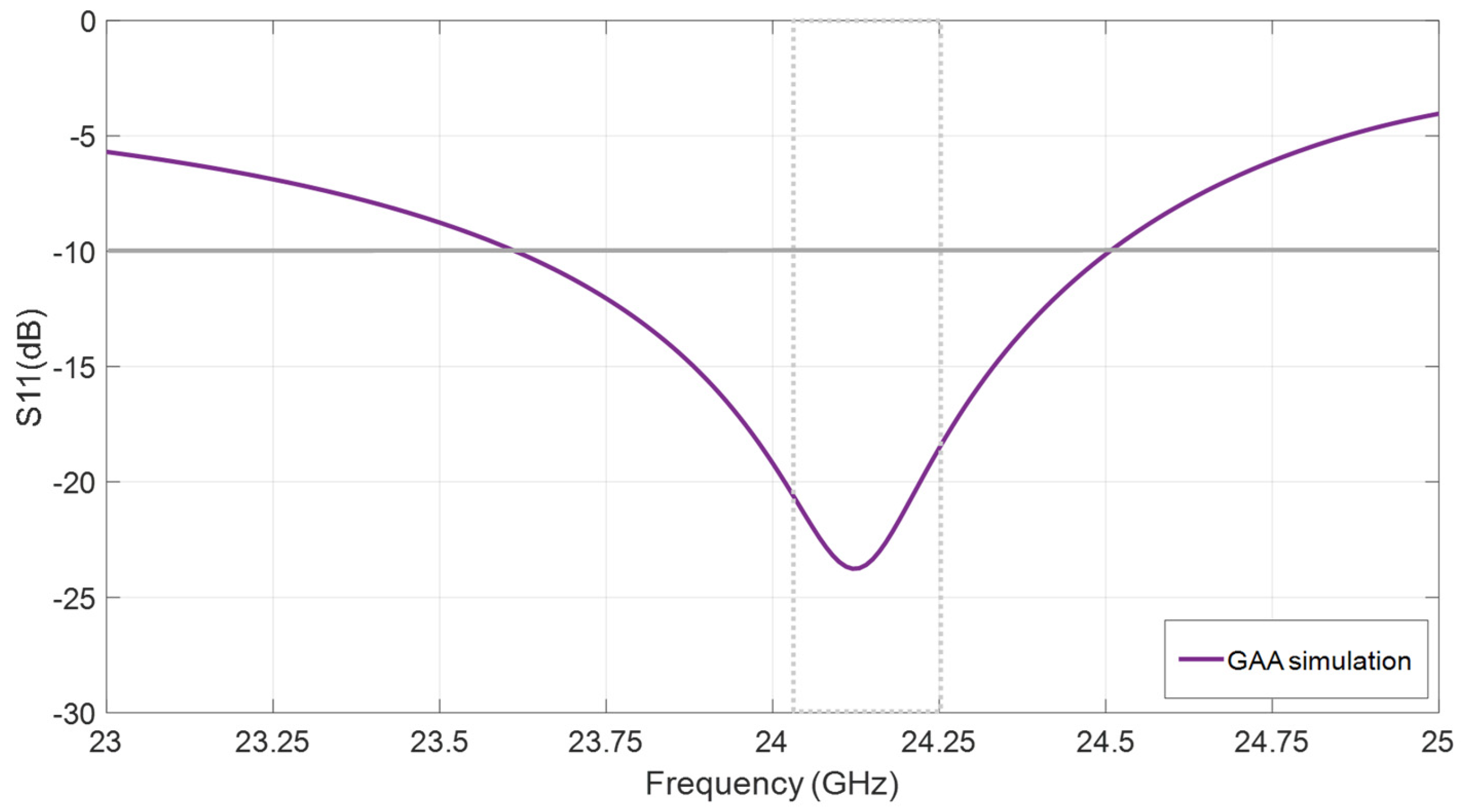
2.3.1. Impedance Matching of the GAA
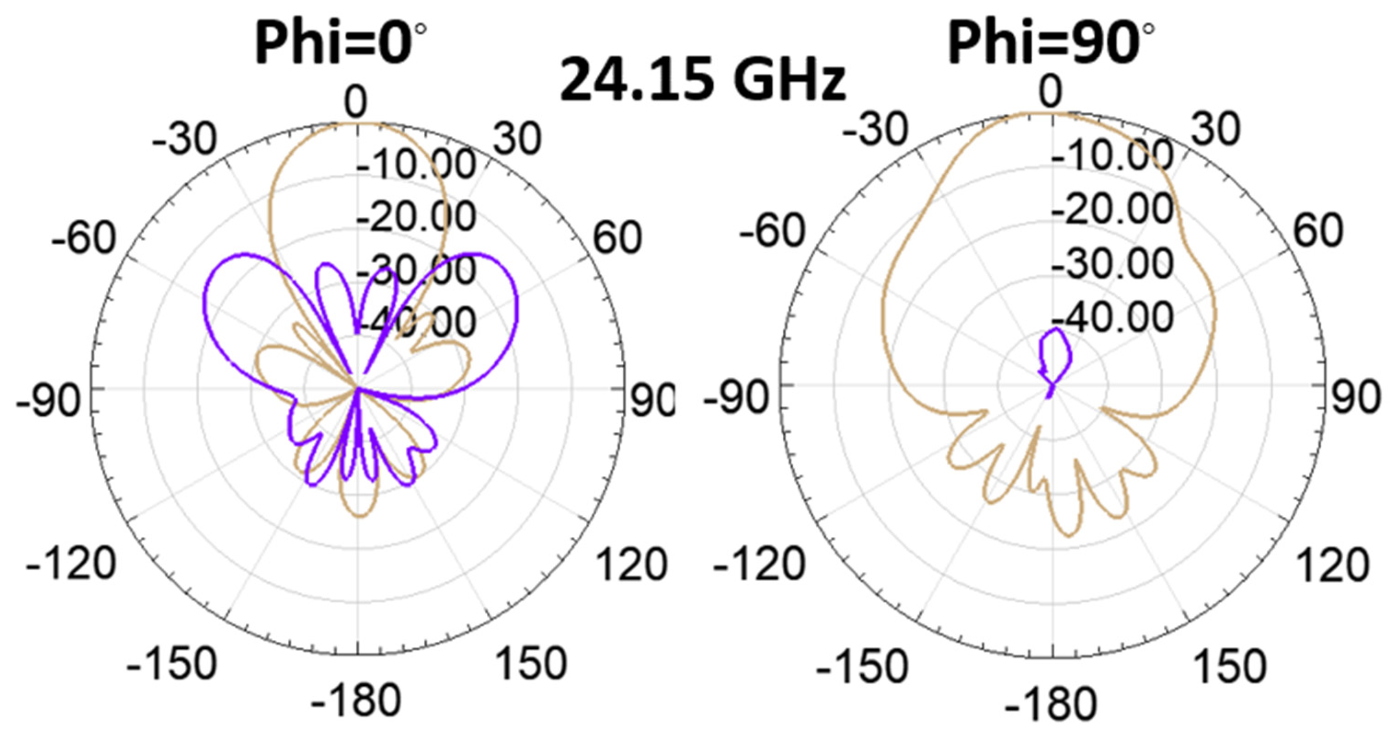
2.3.2. Radiation Characteristics of the GAA
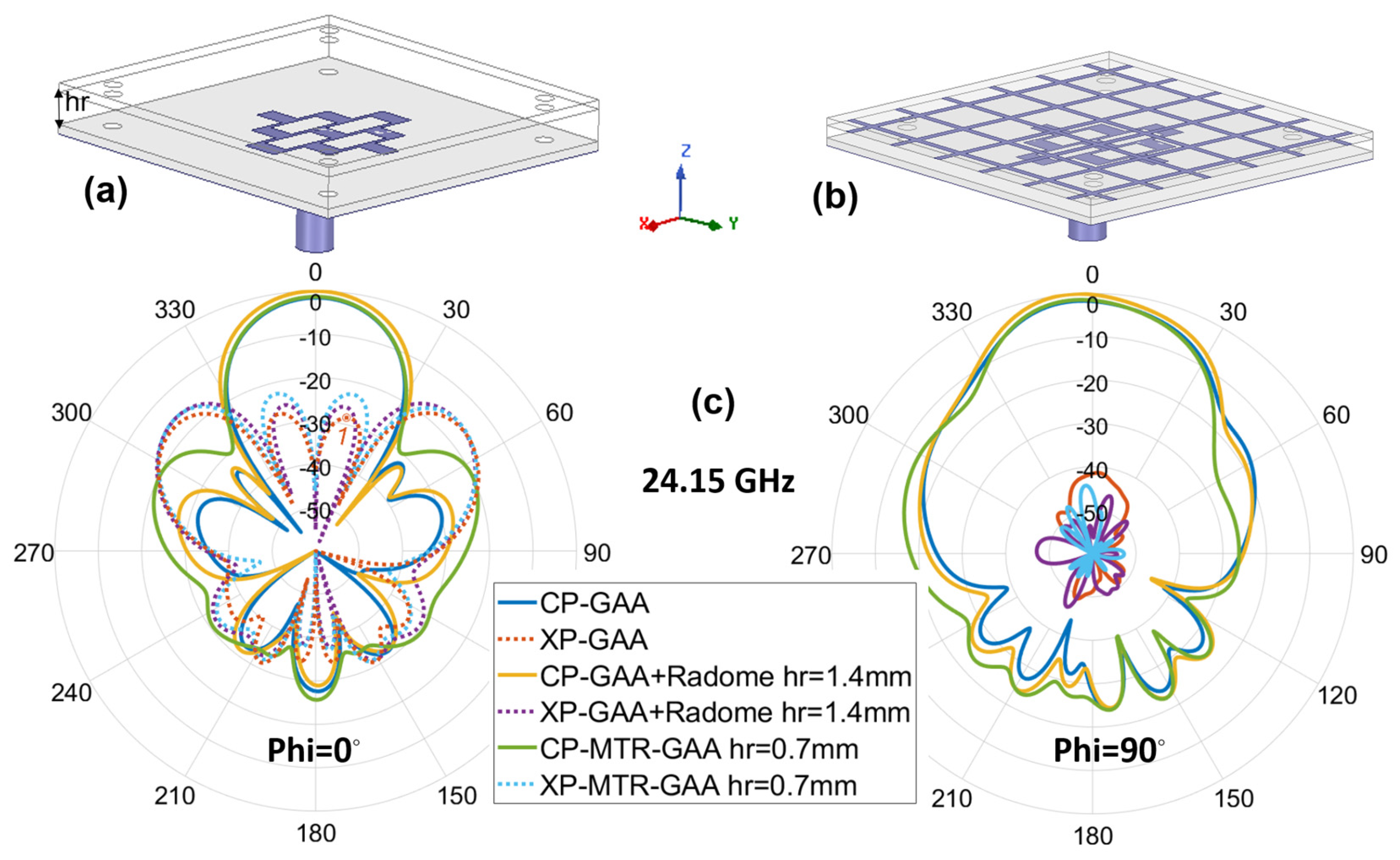
2.4. Metaradome-GAA Combination
3. Results
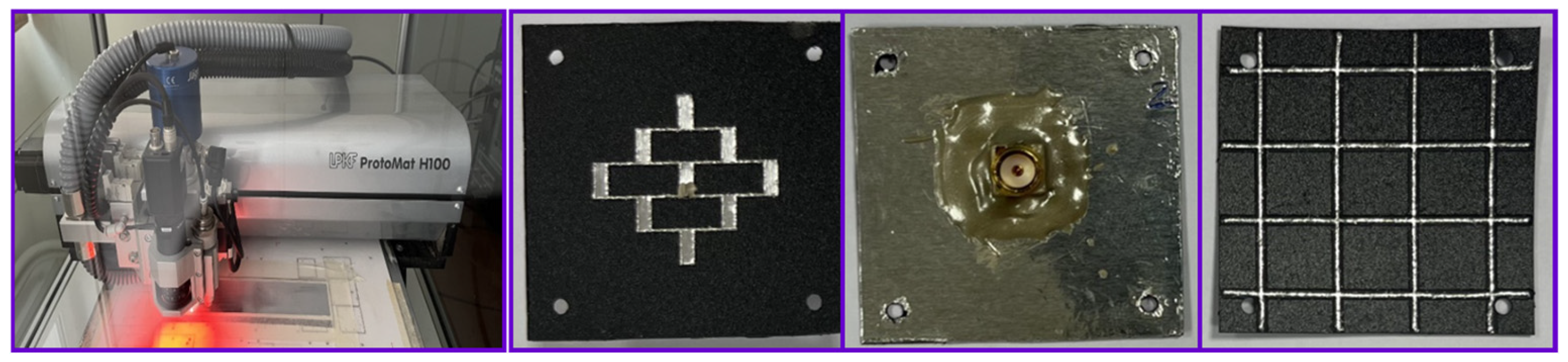
3.1. Fabrication
3.2. Measurement
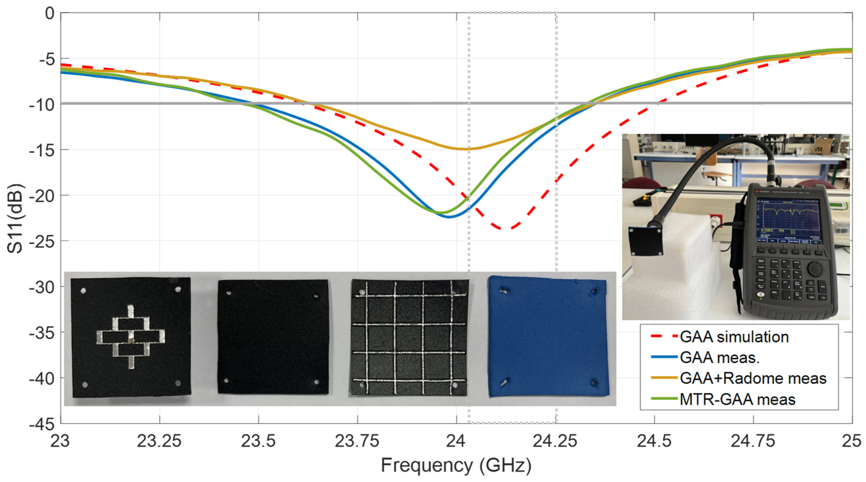
3.2.1. Impedance Matching of the GAA Prototypes
3.2.2. Radiation Characteristics of the GAA Prototypes
4. Discussion
5. Conclusions
Author Contributions
Funding
Institutional Review Board Statement
Informed Consent Statement
Data Availability Statement
Conflicts of Interest
Abbreviations
| GAA | Grid Array Antenna |
| ETA | Electronic Travel Assistance |
| PP | Polypropylene |
| Al | Aluminum |
| MTR | Metaradome |
| WEEE | Waste Electrical and Electronic Equipment |
References
- Argañarás, J.G.; Yan, T.W.; Rezaul, B.; Nemai, C.K. State-of-the-Art Wearable Sensors and Possibilities for Radar in Fall Prevention. Sensors 2021, 21, 6836. [Google Scholar] [CrossRef] [PubMed]
- Ehrlich, J.R.; Ramke, J.; Macleod, D.; Burn, H.; Lee, C.N.; Zhang, J.H.; Waldock, W.; Swenor, B.K.; Gordon, I.; Congdon, N.; et al. Association between vision impairment and mortality: A systematic review and meta-analysis. Lancet Glob. Health 2021, 9, 418–430. [Google Scholar] [CrossRef] [PubMed]
- Abreu, D.; Toledo, J.; Codina, B.; Suárez, A. Low-Cost Ultrasonic Range Improvements for an Assistive Device. Sensors 2021, 21, 4250. [Google Scholar] [CrossRef] [PubMed]
- Cardillo, E.; Caddemi, A. Insight on Electronic Travel Aids for Visually Impaired People: A Review on the Electromagnetic Technology. Electronics 2019, 8, 1281. [Google Scholar] [CrossRef]
- Cardillo, G.E.; Li, C.; Caddemi, A. Millimeter-Wave Radar Cane: A Blind People Aid with Moving Human Recognition Capabilities. IEEE J. Electromagn. RF Microw. Med. Biol. 2022, 6, 204–211. [Google Scholar] [CrossRef]
- Plikynas, D.; Zvironas, A.; Gudauskis, M.; Budrionis, A.; Daniusis, P.; Sliesoraityté, I. Research advances of indoor navigation for blind people: A brief review of technological instrumentation. IEEE Instrum. Meas. Mag. 2020, 23, 22–32. [Google Scholar] [CrossRef]
- Zvironas, A.; Gudauskis, M.; Plikynas, D. Indoor Electronic Traveling Aids for Visually Impaired: Systemic Review. In Proceedings of the 2019 International Conference on Computational Science and Computational Intelligence (CSCI), Las Vegas, NV, USA, 5–7 December 2019; pp. 936–942. [Google Scholar] [CrossRef]
- Long, N.; Yan, H.; Wang, L.; Li, H.; Yang, Q. Unifying Obstacle Detection, Recognition, and Fusion Based on the Polarization Color Stereo Camera and LiDAR for the ADAS. Sensors 2022, 22, 2453. [Google Scholar] [CrossRef]
- Kwiatkowski, P.; Jaeschke, T.; Starke, D.; Piotrowsky, L.; Deis, H.; Pohl, N. A concept study for a radar-based navigation device with sector scan antenna for visually impaired people. In Proceedings of the 2017 First IEEE MTT-S International Microwave Bio Conference (IMBIOC), Gothenburg, Sweden, 15–17 May 2017; pp. 1–4. [Google Scholar] [CrossRef]
- Gao, Y.; Ghasr, M.T.; Zoughi, R. Effects of and Compensation for Translational Position Error in Microwave Synthetic Aperture Radar Imaging Systems. IEEE Trans. Instrum. Meas. 2020, 69, 1205–1212. [Google Scholar] [CrossRef]
- Berdasco, A.F.; Laviada, J.; de Cos Gómez, M.E.; Las-Heras, F. Performance evaluation of millimeter-wave wearable antennas for electronic travel aid. IEEE Trans. Instrum. Meas. 2023, 72, 4507510. [Google Scholar] [CrossRef]
- Kraus, J. A backward angle-fire array antenna. IEEE Trans. Antennas Propag. 1964, 12, 48–50. [Google Scholar] [CrossRef]
- Conti, R.; Toth, J.; Dowling, T.; Weiss, J. The wire grid microstrip antenna. IEEE Trans. Antennas Propag. 1981, 29, 157–166. [Google Scholar] [CrossRef]
- Nakano, H.; Iitsuka, Y.; Yamauchi, J. Rhombic Grid Array Antenna. IEEE Trans. Antennas Propag. 2013, 61, 2482–2489. [Google Scholar] [CrossRef]
- Zhang, L.; Zhang, W.; Zhang, Y.P. Microstrip Grid and Comb Array Antennas. IEEE Trans. Antennas Propag. 2011, 59, 4077–4084. [Google Scholar] [CrossRef]
- Chen, Z.; Ping, Z.Y. 24-GHz microstrip grid array antenna for automotive radars application. In Proceedings of the 2015 IEEE 5th Asia-Pacific Conference on Synthetic Aperture Radar (APSAR), Singapore, 1–4 September 2015; pp. 125–127. [Google Scholar] [CrossRef]
- Assimonis, S.; Samaras, T.; Fusco, V. Analysis of The Microstrip-Grid Array Antenna and Proposal of A New High-Gain, Low-Complexity, and Planar Long-Range WiFi Antenna. IET Microw. Antennas Propag. 2017, 12, 332–338. [Google Scholar] [CrossRef]
- Deepti, D.; Gangwar, S.; Singh, A.; Sharma, S.-P.; Singh, A.; Lay-Ekuakille, A. Design of polarization conversion metasurface for RCS reduction and gain improvement of patch antenna for Ku-band radar sensing applications. Sens. Actuators A Phys. 2022, 333, 113273. [Google Scholar] [CrossRef]
- Roy, A.; Vinoy, K.J.; Martin, N.; Mallégol, S.; Quendo, C. Wideband Absorbing Metasurface for Improving Axial Ratio of a Compact Archimedean Spiral Antenna. IEEE Trans. Antennas Propag. 2023, 71, 151–158. [Google Scholar] [CrossRef]
- Liang, J.; Ding, F.; Fu, Y.; Huang, X.; Jin, J.; Yang, H. Metamaterial microwave sensor with ultrahigh Q-factor based on narrow-band absorption. Sens. Actuators A Phys. 2023, 364, 114779. [Google Scholar] [CrossRef]
- He, Y.; Eleftheriades, G.V. A Thin Double-Mesh Metamaterial Radome for Wide-Angle and Broadband Applications at Millimeter-Wave Frequencies. IEEE Trans. Antennas Propag. 2020, 68, 2176–2185. [Google Scholar] [CrossRef]
- Öziş, E.; Osipov, A.V.; Eibert, T.F. Metamaterials for Microwave Radomes and the Concept of a Metaradome: Review of the Literature. Int. J. Antennas Propag. 2017, 2017, 1–13. [Google Scholar] [CrossRef]
- de Cos Gómez, M.E.; Fernández Álvarez, H.; Flórez Berdasco, A.; Las-Heras Andrés, F. Paving the Way to Eco-Friendly IoT Antennas: Tencel-Based Ultra-Thin Compact Monopole and Its Applications to ZigBee. Sensors 2020, 20, 3658. [Google Scholar] [CrossRef]
- Alsabri, A.; Furqan, T.; Al-Ghamdi, S.G. Environmental impacts of polypropylene (PP) production and prospects of its recycling in the GCC region. Mater. Today Proc. 2022, 56, 2245–2251. [Google Scholar] [CrossRef]
- Bora, R.R.; Wang, R.; You, F. Waste Polypropylene Plastic Recycling toward Climate Change Mitigation and Circular Economy: Energy, Environmental and Technoeconomic Perspectives. ACS Sustain. Chem. Eng. 2020, 8, 16350–16363. [Google Scholar] [CrossRef]
- Galve, J.E.; Elduque, D.; Pina, C.; Javierre, C. Life Cycle Assessment of a Plastic Part Injected with Recycled Polypropylene: A Comparison with Alternative Virgin Materials. Int. J. Precis. Eng. Manuf. -Green Technol. 2022, 9, 919–932. [Google Scholar] [CrossRef]
- de Cos, M.E.; Las-Heras, F. Polypropylene-Based Dual-Band CPW-Fed Monopole Antenna [Antenna Applications Corner]. IEEE Antennas Propag. Mag. 2013, 55, 264–273. [Google Scholar] [CrossRef]
- Garcia-Gamez, L.; Bernard, L.; Collardey, S.; Covic, H.; Sauleau, R.; Mahdjoubi, K. Compact GNSS Metasurface-Inspired Cavity Antennas. IEEE Antennas Wirel. Propag. Lett. 2019, 18, 2652–2656. [Google Scholar] [CrossRef]
- Causse, A.; Rodriguez, K.; Bernard, L.; Sharaiha, A.; Collardey, S. Compact Bandwidth Enhanced Cavity-Backed Magneto-Electric Dipole Antenna with Outer ?-Shaped Probe for GNSS Bands. Sensors 2021, 21, 3599. [Google Scholar] [CrossRef]
- Bernard, L.; Campo, C.; Roussel, E. Eco-friendly based substrates for telemetry antennas in UHF- and S-bands. In Proceedings of the 17th European Conference on Antennas and Propagation (EuCAP), Florence, Italy, 26–31 March 2023; pp. 1–5. [Google Scholar] [CrossRef]
- Poggiani, M.; Alimenti, F.; Mezzanotte, P.; Virili, M.; Mariotti, C.; Orecchini, G.; Roselli, L. 24 GHz patch antenna network in cellulose-based materials for green wireless internet applications. Sci. Meas. Technol. IET 2014, 8, 342–349. [Google Scholar] [CrossRef]
- de Cos Gómez, M.E.; Fernández Álvarez, H.; Las-Heras Andrés, F. Millimeter Wave Antenna on Eco-friendly Substrate for Radar Applications. In Proceedings of the 16th European Conference on Antennas and Propagation (EuCAP), Madrid, Spain, 27 March–1 April 2022; pp. 1–5. [Google Scholar] [CrossRef]
- de Cos Gómez, M.E.; Fernández Álvarez, H.; Las-Heras Andrés, F. PP-based 24 GHz wearable antenna. Wirel. Netw. 2024, 30, 867–882. [Google Scholar] [CrossRef]
- de Cos Gómez, M.E.; Florez Berdasco, A.; Fernández Álvarez, H.; Las-Heras Andrés, F. 24GHz Radar Antenna on Eco-Friendly Substrate. In Proceedings of the 17th European Conference on Antennas and Propagation (EuCAP), Florence, Italy, 26–31 March 2023; pp. 1–5. [Google Scholar] [CrossRef]
- Achillas, C.; Vlachokostas, C.; Koroneos, C. Life cycle thinking: Towards the sustainable management of resources in aluminum production. Euro-Mediterr. J. Environ. Integr. 2020, 5, 16. [Google Scholar] [CrossRef]
- de Cos Gómez, M.E.; Florez Berdasco, A.; Las-Heras Andrés, F. Simulations and Measurements Dataset of ETA Radar Sensing Antenna. Available online: https://data.mendeley.com/datasets/3yc8x8z982/1 (accessed on 6 February 2025).
- IEEE Std 149-2021; IEEE Recommended Practice for Antenna Measurements. IEEE: Piscataway, NJ, USA, 2022; pp. 1–207 (accessed on 16 January 2024). [CrossRef]
- SAM-2432431750-KF-L1 K Band Microstrip Patch Array Antenna. Available online: https://sftp.eravant.com/content/datasheets/SAM-2432431750-KF-L1.pdf (accessed on 6 February 2025).
- Jung, Y.; Park, D.; Jung, C.W. Low cost 24GHz patch array antenna for high sensitivity EM sensor. In Proceedings of the 2010 Asia-Pacific Microwave Conference, Yokohama, Japan, 7–10 December 2010; pp. 2208–2211. [Google Scholar]
- Slovic, M.; Jokanovic, B.; Kolundzija, B. High efficiency patch antenna for 24 GHz anticollision radar. In Proceedings of the TELSIKS 2005 International Conference on Telecommunication in Modern Satellite, Cable and Broadcasting Services, Nis, Serbia, 28–30 September 2005; Volume 1, pp. 20–23. [Google Scholar]
- Wang, L.L.; Zhang, S.Y.; Li, J.J.; Fan, P.P. Array antenna for 24 GHz automotive radar. Chin. J. Radio Sci. 2024. (In Chinese) [Google Scholar] [CrossRef]
- Milijic, M.; Jokanovic, B. Design of the Crossed Slot Antenna Array for 24 GHz Short Range Radars. In Proceedings of the 11th International Conference on Electrical, Electronic and Computing Engineering (IcETRAN), Nis, Serbia, 3–6 June 2024; pp. 1–4. [Google Scholar] [CrossRef]
- Chaudhuri, S.; Mishra, M.; Kshetrimayum, R.S.; Sonkar, R.K.; Chel, H.; Singh, V.K. Rectangular DRA Array for 24 GHz ISM-Band Applications. IEEE Antennas Wirel. Propag. Lett. 2020, 19, 1501–1505. [Google Scholar] [CrossRef]
- Dawood, H.; Zahid, M.; Awais, H.; Shoaib, S.; Hussain, A.; Jamil, A. A High Gain Flexible Antenna for Biomedical Applications. In Proceedings of the 2020 International Conference on Electrical, Communication, and Computer Engineering (ICECCE), Istanbul, Turkey, 12–13 June 2020; pp. 1–4. [Google Scholar] [CrossRef]
- Kathuria, N.; Seet, B.-C. 24 GHz Flexible Antenna for Doppler Radar-Based Human Vital Signs Monitoring. Sensors 2021, 21, 3737. [Google Scholar] [CrossRef] [PubMed]
- Yao, K.; Lan, S.; Tang, H.; He, Z.; Yang, C. A 24GHz Micropatch Antenna Array for Human Hand Gestures Detection. In Proceedings of the 2018 USNC-URSI Radio Science Meeting (Joint with AP-S Symposium), Boston, MA, USA, 8–13 July 2018; pp. 95–96. [Google Scholar] [CrossRef]
- Chen, Y.; Shi, J.; Xu, K.; Lin, L.; Wang, L. A Compact Wideband Quasi-Yagi Antenna for Millimeter-Wave Communication. IEEE Antennas Wirel. Propag. Lett. 2023, 22, 1481–1485. [Google Scholar] [CrossRef]
- Xu, S.; Xu, H.; Dong, R.; Deng, C. Design of 24 GHz Microstrip Array Antenna for Automotive Radar. In Proceedings of the International Conference on Microwave and Millimeter Wave Technology (ICMMT), Bejing, China, 16–19 May 2024; pp. 1–3. [Google Scholar] [CrossRef]
- Zhou, H.; Geng, J.; Jin, R. A Magnetic Yagi-Uda Antenna with Vertically Polarized Endfire Radiation in Millimeter-Wave Band Applying Higher Order Mode. IEEE Trans. Antennas Propag. 2022, 70, 8941–8950. [Google Scholar] [CrossRef]
- He, Y.; Ma, K.; Yan, N.; Wang, Y.; Zhang, H. 3-D SISL Feeding Network for 2-D Cavity-Backed Endfire Dipole Array at 24 GHz. IEEE Antennas Wirel. Propag. Lett. 2023, 22, 990–994. [Google Scholar] [CrossRef]
- Sharma, M.; Gautam, A.K.; Agrawal, N.; Singh, N. Design of MIMO planar antenna at 24 GHz band for radar, communication and sensors applications. AEU Int. J. Electron. Commun. 2021, 136, 153747. [Google Scholar] [CrossRef]
- Shan, J.; Rambabu, K.; Zhang, Y.; Lin, J. High gain array antenna for 24 GHz FMCW automotive radars. AEU Int. J. Electron. Commun. 2022, 147, 154144. [Google Scholar] [CrossRef]


| Frequency Band | |||
|---|---|---|---|
| Freq (GHz) | BW | ||
| fLow | fUp | Total (MHz) | % |
| 23.60 | 24.51 | 910 | 3.8 |
| Freq (GHz) | G (dBi) | D (dB) | η (%) | FTBR (dB) | SLL (dB) φ = 0° | HPBW (°) φ = 0° | SLL (dB) φ = 90° | HPBW (°) φ = 90° |
|---|---|---|---|---|---|---|---|---|
| 24.05 | 14.2 | 14.4 | 94 | 22.9 | −30 | 30 | −15 | 40 |
| 24.15 | 14 | 14.3 | 93 | 22.9 | ||||
| 24.25 | 13.7 | 14.2 | 89 | 22.9 |
| GAA+Radome | MTR-GAA | |||||
|---|---|---|---|---|---|---|
| hr (mm) | G (dBi) | η (%) | FTBR (dB) | G (dBi) | η (%) | FTBR (dB) |
| 0.3 | 12.0 | 69 | 23.2 | 12.3 | 82 | 21 |
| 0.5 | 12.8 | 77 | 24.4 | 13.1 | 87 | 21.5 |
| 0.7 | 12.3 | 81 | 23.5 | 13.4 | 88 | 22.7 |
| 0.9 | 13.4 | 83 | 23.8 | 13.6 | 88 | 24.7 |
| 1.2 | 13.7 | 86 | 23.9 | 13.8 | 88 | 25.1 |
| 1.4 | 13.8 | 88 | 24.5 | 13.6 | 87 | 25 |
| Freq (GHz) | G (dBi) | ||
|---|---|---|---|
| GAA | GAA+Radome | GAA+Metaradome | |
| 24.05 | 12.5 | 11.7 | 12.7 |
| 24.15 | 12.5 | 11.5 | 12.5 |
| 24.25 | 12.1 | 11.0 | 12.0 |
| Ref. | Size (mm3) | εr | BW (GHz) | BW (%) | S11 (dB) |
|---|---|---|---|---|---|
| [16] | 60 × 60 × 0.787 | 2.2 | 1.99 | 8.2 | −34 |
| [31] | 20 × 20 × 0.68 | 2.9 | 2.0 | 8.3 | −35 |
| [32] | 98.7 × 14.4 × 0.52 | 2.2 | 0.28 | 1.2 | −25 |
| [34] | 60 × 60 × 0.52 | 2.2 | 0.96 | 4.0 | −26 |
| [37] | 74.9 × 74.9 × 3.3 | - | 0.2 | 1.0 | −8 |
| [39] | 160 × 43.2 × 0.5 | 2.3 | 0.32 | 1.3 | −20 |
| [40] | 230 × 31 × 0.254 | 2.17 | 0.39 | 1.6 | −20 |
| [41] | 73.5 × 55 × 0.254 | 2.2 | 0.83 | 3.4 | −42 |
| [42] | 143 × 18.5 × 3.625 | 2.54 | 2.25 | 9.7 | −17 |
| [49] | 32.4 × 15 × 1.016 | 2.2 | 2 | 8.0 | −28 |
| [50] | 24 × 21 × 43.3 | 2.2 | 2.75 | 11.7 | −38 |
| [51] | 40 × 6 × 0.8 | 2.2 | 4.44 | 18 | −20 |
| [52] | 86 × 86 × 0.254 | 2.2 | 0.77 | 3.2 | −25 |
| This work | 40.8 × 40.8 × 0.52 | 2.2 | 0.94 | 3.9 | −24 |
| This + MTR | 40.8 × 40.8 × 1.74 | 2.2 | 0.70 | 2.9 | −35 |
| Ref. | G (dBi) | η (%) | SLL (dB) φ = 0° | HPBW (°) φ = 0° | SLL (dB) φ = 90° | HPBW (°) φ = 90° |
|---|---|---|---|---|---|---|
| [16] | 20.6 | - | −15 | 16 | −25 | 16 |
| [31] | 7.4 | 35 | - | 54 | −25 | 48 |
| [32] | 16.8 | 91 | −18 | 9.2 | −25 | 64 |
| [34] | 20.8 | 98 | −17 | 15 | −20 | 16 |
| [37] | 17 | - | −20 | 12 | −20 | 50 |
| [39] | 17 | - | −18 | 8.2 | −18 | 80 |
| [40] | 21.7 | 60 | −21 | 3.6 | −21 | 46 |
| [41] | 22.7 | 96 | −21 | 13 | −23 | 10 |
| [42] | 18.7 | - | −19 | 8 | - | - |
| [49] | 8 | - | −10 | 60 | −20 | 30 |
| [50] | 20.6 | 88 | −15 | 15 | −15 | 15 |
| [51] | 9.8 | 87 | - | - | - | - |
| [52] | 25.9 | - | −20 | 15 | −24.5 | 13.3 |
| This work | 14 | 93 | −30 | 30 | −15 | 40 |
| This + MTR | 13.4 | 88 | −20 | 30 | −15 | 40 |
Disclaimer/Publisher’s Note: The statements, opinions and data contained in all publications are solely those of the individual author(s) and contributor(s) and not of MDPI and/or the editor(s). MDPI and/or the editor(s) disclaim responsibility for any injury to people or property resulting from any ideas, methods, instructions or products referred to in the content. |
© 2025 by the authors. Licensee MDPI, Basel, Switzerland. This article is an open access article distributed under the terms and conditions of the Creative Commons Attribution (CC BY) license (https://creativecommons.org/licenses/by/4.0/).
Share and Cite
de Cos Gómez, M.E.; Flórez Berdasco, A.; Las-Heras Andrés, F. Eco-Friendly Metadome-Antenna Innovations for Wearable Millimeter Wave Radar Sensing. Appl. Sci. 2025, 15, 2674. https://doi.org/10.3390/app15052674
de Cos Gómez ME, Flórez Berdasco A, Las-Heras Andrés F. Eco-Friendly Metadome-Antenna Innovations for Wearable Millimeter Wave Radar Sensing. Applied Sciences. 2025; 15(5):2674. https://doi.org/10.3390/app15052674
Chicago/Turabian Stylede Cos Gómez, María Elena, Alicia Flórez Berdasco, and Fernando Las-Heras Andrés. 2025. "Eco-Friendly Metadome-Antenna Innovations for Wearable Millimeter Wave Radar Sensing" Applied Sciences 15, no. 5: 2674. https://doi.org/10.3390/app15052674
APA Stylede Cos Gómez, M. E., Flórez Berdasco, A., & Las-Heras Andrés, F. (2025). Eco-Friendly Metadome-Antenna Innovations for Wearable Millimeter Wave Radar Sensing. Applied Sciences, 15(5), 2674. https://doi.org/10.3390/app15052674