Article

A New Low-Cost Compact Antenna for the 2.45 and 5.8 GHz ISM Bands

UMR 5005, Ampère, CNRS, Université Claude Bernard Lyon 1, INSA Lyon, Ecole Centrale de Lyon, Univ Lyon, 69130 Ecully, France
*
Author to whom correspondence should be addressed.
Appl. Sci. 2025, 15(4), 1912; https://doi.org/10.3390/app15041912
Submission received: 17 December 2024 / Revised: 9 February 2025 / Accepted: 10 February 2025 / Published: 12 February 2025
(This article belongs to the Special Issue Recent Advances in Antennas and Propagation)

Abstract

:
This paper presents the design of a high-performance dual-band antenna for industrial, scientific, and medical (ISM) band applications. The proposed prototype consists of a low-cost patch antenna, 40 mm × 24 mm in size (i.e., 0.36λ0 × 0.19λ0, with λ0 the wavelength corresponding to the low frequency), with a relatively wideband for both operational bands (up to 140 MHz at 2.45 GHz and 510 MHz at 5.8 GHz), and a radiation efficiency of over 90%. The antenna has a quasi-omnidirectional radiation pattern with gains of 2.41 dBi and 5.22 dBi at 2.45 GHz and 5.8 GHz, respectively. The design methodology is detailed and illustrated by simulation results showing the optimization steps and the characteristics associated with the antenna. Experimental results based on a fabricated prototype are presented and compared with simulation results from the design stage. Finally, the proposed antenna prototype is also compared with similar antennas available in the literature.

1. Introduction

The rapid and continuous advancement of wireless communication technologies has resulted in the proliferation of numerous radio standards that must coexist within modern communication systems [1]. This has been driven by the growing prevalence of connected devices, including personal computers, smartphones, IoT sensors, Wi-Fi routers, and Bluetooth-enabled peripherals, which frequently incorporate multiple radio frequency (RF) technologies tailored for diverse applications and operating across distinct frequency bands [2]. Among the critical components of any wireless system, the antenna stands out as a fundamental and indispensable element, as it facilitates the transmission and reception of electromagnetic signals. However, the integration of antennas into compact and multifunctional devices poses several design challenges. Primarily, the physical dimensions of the antenna often impose substantial constraints on the overall design of the device. These constraints are exacerbated by the need to ensure adequate isolation of the antenna from other radiating elements within the system, as well as from components operating at baseband frequencies. This isolation is essential to minimize interference, maintain signal integrity, and ensure optimal performance across the various RF technologies present in the system. Moreover, in many communication systems, the antenna is one of the largest individual components, frequently occupying a significant proportion of the device’s volume [3]. Consequently, these challenges highlight the critical need for innovative antenna design approaches, including the development of miniaturized, multi-band, and highly efficient antennas that can seamlessly integrate into increasingly constrained form factors without compromising performance.
A wide variety of antenna types are suitable for embedded applications, including wire antennas [4], aperture antennas [5], metasurface reflectors [6], and microstrip patch antennas [7,8]. Among these, microstrip patch antennas (often referred to as printed-on-substrate antennas) have garnered sustained attention from researchers over the past several decades. These planar antennas have been extensively studied due to their numerous advantages: compact size, lightweight construction, cost-effectiveness, and straightforward manufacturing processes. Additionally, their inherent planar structure facilitates seamless integration into compact electronic devices [9]. To address the evolving demands of modern wireless communications, significant advancements have been made in microstrip antenna technology. Miniaturization techniques have enabled these antennas to achieve highly compact designs without compromising performance [10]. Furthermore, innovative approaches have expanded their operational bandwidth, allowing them to function effectively across multiple frequency bands, thereby enhancing their versatility for diverse applications [11]. Consequently, microstrip patch antennas are an essential component of wireless communication systems, and their design and optimization provide solutions in terms of efficiency, reliability, and integration of wireless devices.
Electromagnetic (EM) energy recovery devices have recently emerged as a promising area of research, drawing increasing attention from the scientific community. The pervasive presence of radiofrequency (RF) waves in modern environments offers an opportunity to repurpose these waves, without compromising their primary function of information transmission within standardized protocols, as an alternative energy source. Through RF-to-DC conversion, this harvested energy can be used to power low-energy devices, such as wireless sensors and IoT nodes [12]. This approach aligns well with the growing demand for sustainable and self-powered technologies in smart environments.
In this context also, the size and frequency versatility of antennas play a pivotal role. Compact and multiband antennas, in particular, provide significant advantages. Their ability to operate across multiple frequency bands enhances their adaptability to fluctuating RF environments, where the available frequencies or signal intensities may vary over time or space, especially critical for mobile devices operating in dynamic settings [13]. The multiband functionality ensures greater robustness and efficiency, making these antennas suitable for both current and future wireless systems. Moreover, the dual capability of antennas to support both wireless information transmission and wireless energy transfer provides an added layer of efficiency. A single multiband antenna can replace multiple narrow-band antennas dedicated to individual functions, leading to reduced costs, simplified device architecture, and a smaller ecological footprint. This integrated approach aligns with the principles of sustainable design, emphasizing resource efficiency while meeting the demands of modern wireless communication and energy harvesting systems.
The ISM (Industrial, Scientific, and Medical) bands refer to frequency ranges allocated globally for non-commercial purposes that do not require a license for operation. Spanning from a few megahertz (MHz) to several hundred gigahertz (GHz), these bands serve a diverse range of applications in various domains. Their flexibility and widespread availability make them particularly appealing for systems requiring cost-effective and accessible wireless communication. Originally designated for industrial heating, scientific research, and medical diagnostics, the ISM bands have since become a cornerstone for innovative technologies. Among these, the 2.45 GHz and 5.8 GHz bands hold particular significance due to their unique balance between propagation characteristics and bandwidth availability. The 2.45 GHz band, for instance, has become the foundation for biotelemetry systems, enabling real-time patient monitoring and data transmission in healthcare environments [14,15]. Similarly, the 5.8 GHz band, with its higher frequency and broader bandwidth, supports advanced applications such as high-resolution passive radar systems and precise location tracking [16]. Both bands also play a vital role in wearable and body-centric communications, particularly in the textile industry, where lightweight, portable systems are required for off-body and on-body networks [17].
Designing and deploying a microstrip antenna that operates effectively within the 2.45 GHz and 5.8 GHz ISM frequency bands represents a pivotal step in advancing the mass adoption of miniaturized connected devices. These antennas, known for their compactness, lightweight structure, and ease of integration, are particularly well-suited for modern applications that demand both efficiency and scalability. By optimizing performance in these specific frequency ranges, microstrip antennas enable more reliable and energy-efficient wireless communication, which is crucial for the proliferation of the Internet of Things (IoT) and other interconnected ecosystems. Moreover, leveraging these bands helps maximize the use of globally available radio resources, addressing challenges such as spectral congestion and power efficiency. The dual-band functionality further enhances versatility, allowing seamless operation across a variety of applications, from wearable devices and biotelemetry to high-speed data transmission and radar systems. This dual-frequency approach also facilitates innovations in adaptive antenna designs, such as beam steering and frequency agility, which contribute to superior network performance and resilience.
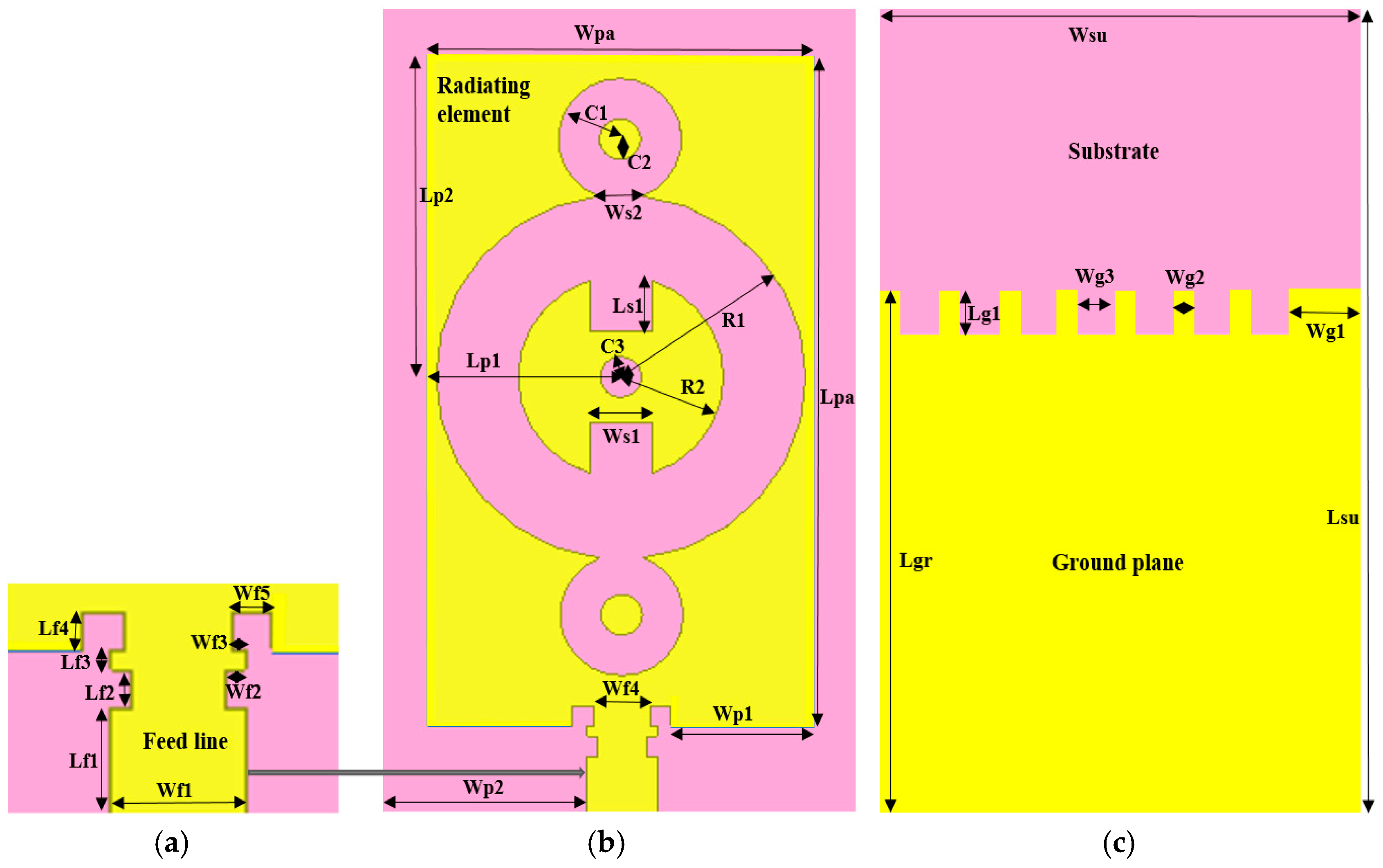
Microstrip antennas consist mainly of a radiating element, commonly called a patch, a substrate, and a ground plane. These antennas fall into two categories, depending on the shape of the radiating element, which influences the nature of the radiation. These are monopole patch antennas (wired radiating element) [18] and microstrip antennas with a large radiating surface [19]. Small patch antennas generally have low gain and reduced bandwidth. To improve the performance of these antennas, notably, in terms of bandwidth, gain, and efficiency, slots can be inserted in the radiating element in the case of microstrip antennas with a large radiating surface [20]. Several types of monopole [21,22] and large-area patch antennas [23,24] operating in the 2.45 GHz and 5.8 GHz bands are presented in the literature. As far as slot geometry is concerned, there are several shapes, such as L, T [19], rectangular [23], or fractal geometry [23,24], that enable multiband antenna operation.
The dielectric substrate can also influence the performance parameters of patch antennas. Indeed, patch antennas with thick, low-dielectric-constant substrates offer higher efficiency, greater bandwidth, and fields that are less restrictive to radiation in space. On the other hand, antennas with thin substrates and high dielectric constants result in high losses and low bandwidth. Several types of substrates are often used to design patch antennas: Rogers [25], Epoxy Flame Retardant-4 (FR-4) [26], PEC [27], Teflon [28], Textile [29], and RT Duroid [30]. Flexible substrates such as polydimethylsiloxane (PDMS) and PF4-foam materials [18] are also used. However, the most commonly used substrate is FR-4 epoxy (despite its high loss tangents) due to its low cost, ease of manufacturing, suitability for mass production, and relatively high performance. Additionally, FR-4 is highly water-resistant and does not absorb moisture.
The aim of the study presented here is to design a dual-band antenna operating at ISM frequencies 2.45 GHz and 5.8 GHz, targeting, for example, common WLAN standards such as Bluetooth, Wi-Fi, and Wi-MAX. More specifically, in addition to an antenna operating at these two frequencies, we are looking for a good compromise between performance, size, and cost. Section 2 describes the initial choices made, and the step-by-step methodology followed, with particular emphasis on optimization. Section 3 focuses on the impact of the initially chosen rectangular patch topology (including the effect of inserting slots and notches on the patch antenna) at the various stages of antenna design, with the antenna’s reflection coefficient as the main criterion. In Section 4, the manufactured prototype is experimentally characterized, showing good agreement with the simulations presented. A comparative overview of antennas of the same type in the literature is also provided. Section 5 concludes this study and opens up a few perspectives.

2. Dual-Band Antenna Design

2.1. Technical Specifications and Choice of Antenna Type

The objective of the design is to provide a compact, low-cost, dual-band antenna operating at 2.45 GHz and 5.8 GHz with high performance; more specifically, (i) a reflection coefficient of less than 10 dB, (ii) a bandwidth of at least 100 MHz, (iii) a gain of at least 2 dBi, and (iv) an efficiency of at least 80% in both bands.
In particular, patch antennas (or printed-on-substrate antennas) are designed chosen because they occupy little space in RF energy collection systems and can offer robust and inexpensive solutions. Consequently, in order to obtain a low-cost, relatively compact, and high-performance antenna, a microstrip patch antenna integrating slots based on a FR-4 substrate is chosen for this work.

2.2. Proposed Antenna Configuration

First, it should be noted that all the simulation results presented were obtained using the high-frequency simulation software HFSS-version 13.0.
The proposed antenna is rectangular in shape and fed by a centered microstrip line. The advantage of choosing a rectangular shape is that rectangular patch antennas can be sized according to theoretical equations [31]. The radiating element and ground plane have a thickness of 0.035 mm, which represents the most economical standard PCB (printed circuit board) thickness. The substrate used for the antenna design (FR-4 epoxy) has a relative permittivity of 4.4, a loss tangent of 0.02, and a thickness of 1.6 mm. For simplicity’s sake, the feed line is a microstrip placed in the same plane as the radiating element.
The proposed antenna configuration after optimization steps is shown in Figure 1. Figure 1a,b show a top view of the antenna, with the radiating element and feed line coplanar and positioned on the dielectric substrate. Figure 1c shows the bottom view of the antenna. The antenna features circular and rectangular slots.
Inspired by the works in [31], the antenna feed line shown in Figure 1a features a pair of rectangular notches in its upper part (at the lower limit of the radiating element), followed by another pair of square notches inserted on the sides. Considering Figure 1b, on the radiating element, the designed antenna has three ring-shaped slots. Inside the central ring with radii R1 and R2 are three slots, two of which are rectangular and identical, symmetrical to the third circular slot. The ground plane shown in Figure 1c has a partial length with respect to the dielectric substrate. The upper part of the ground plane is crenellated due to the insertion of square slots.
Analytical calculations [31] for sizing patch antennas are best suited to single-band antennas and do not guarantee the achievement of other desired matching frequencies in the case of a multiband antenna because sizing is performed at a single frequency (the lowest in the case of a multiband antenna). Thus, the purpose of the slots created on the antenna is, on the one hand, to obtain two frequencies adapted to ISM bands and, on the other, to improve the antenna’s reflection parameters and performances. The dimensions and position of the slots in the occurrence of those of the central ring are chosen to favor frequency shifting or the obtaining of the second frequency band. The other slots of the radiating element are inserted to adjust the antenna to its central matching frequencies.
Table 1 presents the dimensions of each element of the antenna (slots, patch, feed line, substrate, and ground plane). The optimized dimensions of the patch (Lpa × Wpa) and substrate (Lsu × Wsu) are 33 mm × 18.5 mm and 40 mm × 24 mm, respectively.

2.3. Antenna Design Methodology

To size the antenna, a frequency of 2.45 GHz is initially chosen. In fact, an antenna whose dimensions are obtained from a given frequency is capable of operating in higher frequency bands. As with any antenna, there is not just one resonant frequency but many multiples of it. From [31], considering the previous parameters and the low frequency (i.e., 2.45 GHz), the dimensions of the patch (Lp × Wp) and the ground plane (Ls × Ws), here identical to those of the substrate, are equal to 37.23 mm × 28.81 mm and 46.23 mm × 38.41 mm, respectively. One technique for making other main resonances appear (which can also be repeated on even and odd multiples) and minimizing the antenna size would be to insert slots on the antenna. Our aim is to introduce the second 5.8 GHz frequency band and optimize the antenna’s performance. The optimization objective was constrained by the conditions (i) to (iii) set out above.
Figure 2 shows the four different steps in the antenna design process. Initially, in step 1 (Figure 2a), the ground plane is modified by reducing its length, followed by the insertion of a pair of 1 mm × 1 mm square notches at the intersection of the patch and the supply line. These notches and the partial ground plane are proposed to improve the antenna’s reflection parameters and minimize its size, always inspired by the authors’ work in [30]. In step 2, a circular ring is introduced (Figure 2b) on the patch, and a second pair of 1 mm × 0.5 mm rectangular notches is then inserted in the lower part of the feed line. Three 2 mm × 2 mm square slots and two circular slots are inserted in the upper part of the ground plane and symmetrical to the central ring in the third step, respectively, in Figure 2c. The final antenna is obtained by adding three slots to the patch, two of which are rectangular (Figure 2d). The ground plane is also modified by creating four other square slots in its upper part. The idea behind the shape of the ground plane is to extend its upper edge to enhance the electromagnetic diffraction effects of its boundaries, which will contribute to increasing the electromagnetic radiation of the patch. The slots are inserted on the patch to prevent or reduce the propagation of surface waves (that affect the antenna’s bandwidth and radiation efficiency) and to create a new current distribution that would influence frequencies in terms of reflection coefficient levels and improve the antenna’s bandwidth.
The circular and rectangular slots are inserted to considerably increase the distance that the surface current would travel across the patch. Indeed, a current flowing from one end of the patch to the other is generally blocked by the slots. To bypass them, it will have to take a longer path than the one without the slots inserted, which would increase the length covered by the current. The result would be a lengthening of the wavelength or a reduction in the antenna’s operating frequency. This technique can be used to reduce operating frequencies or shift the frequency of resonance points.

3. Parameters Study and Simulation Results

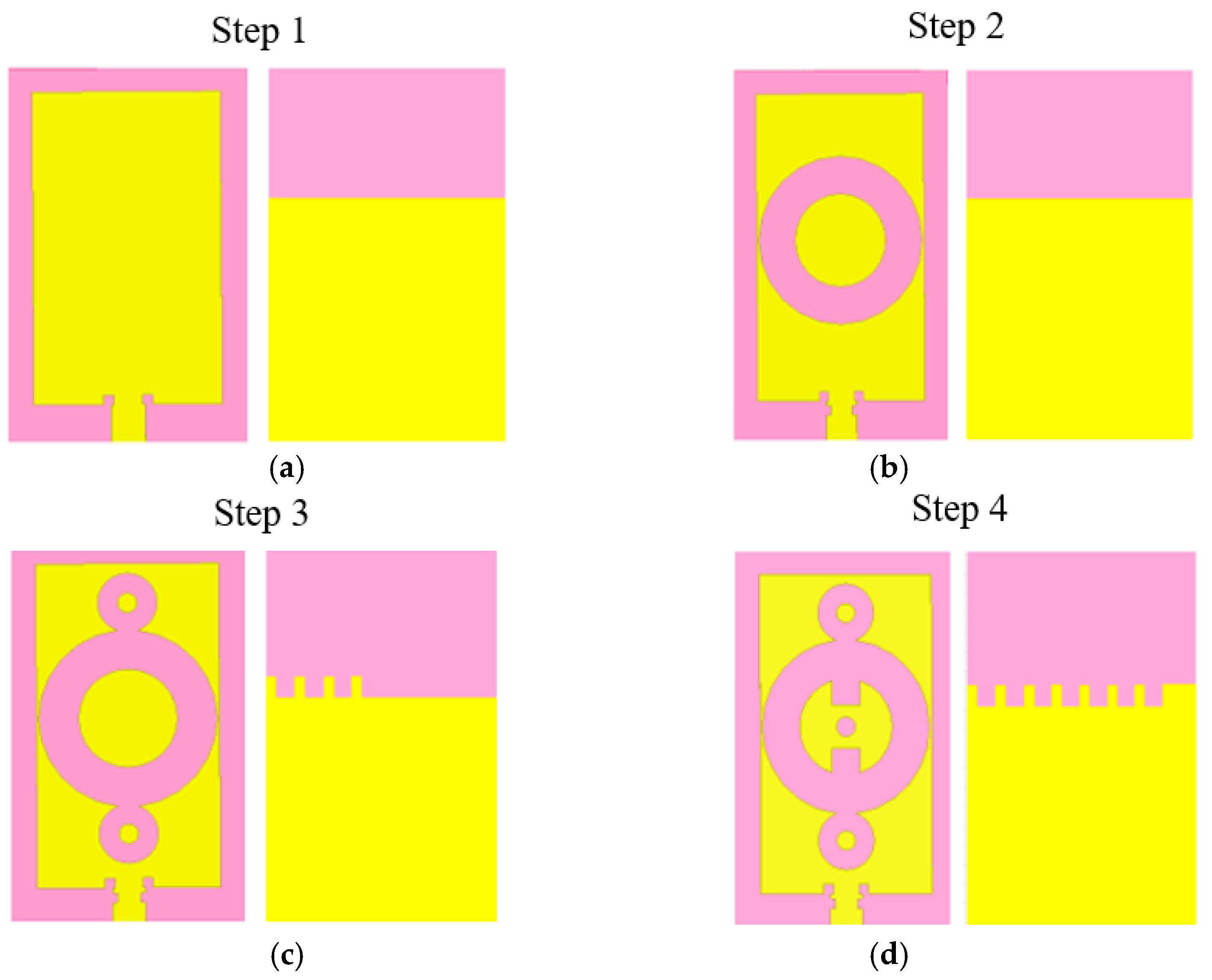
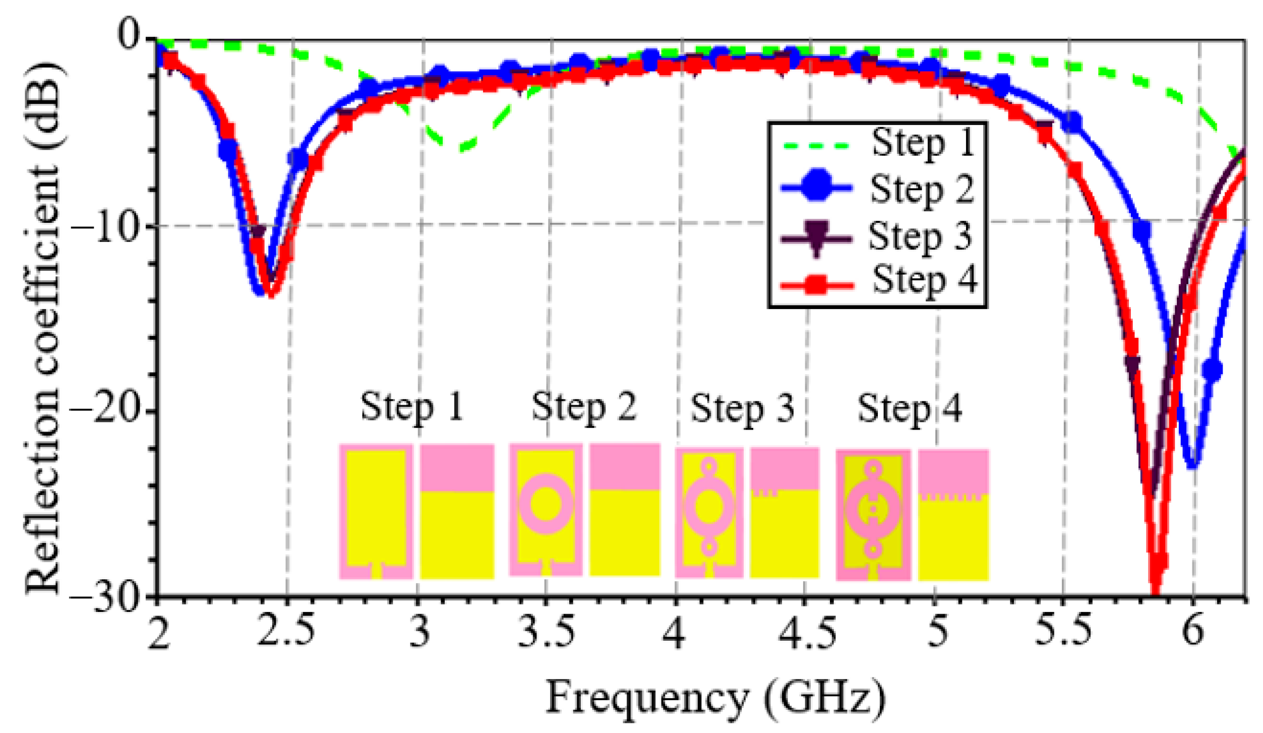
The antenna’s reflection coefficient at the four steps is shown in Figure 3. It should be noted that the frequency bands obtained after the simulation of the antenna corresponding to the initial structure (step 1) are not adapted to ISM frequencies. At design step 1, the antenna has two desired operating frequencies, but with a significant frequency offset, namely, 3.1 GHz and 6.8 GHz (not visible on the curve, as this latter frequency is not of interest here), and a reflection coefficient greater than 10 dB ( 6.2 dB) at 3.1 GHz. In step 2, the antenna has two frequency bands very close to the two ISM bands, i.e., 2.41 GHz and 6 GHz. At these frequency bands, the reflection coefficient is less than 10 dB. Step 3 of the design resulted in the two desired ISM frequency bands. Finally, in step 4, an improvement in antenna impedance matching and bandwidth around the two ISM center frequencies is observed.
Table 2 shows the antenna performance parameters at optimization steps from 2 to 4. From the first to the last optimization step, there is a 77% and 30% increase in bandwidth at frequencies of 2.45 GHz and 5.8 GHz, respectively.

3.1. Impact of Circular Ring Radius at Design Step 2

The antenna structure in step 2 is obtained by inserting the slots on the feed line and then modifying the dimensions and position of the circular ring inserted. It should be noted that the notches had little effect on the frequency bands and reflection coefficients.
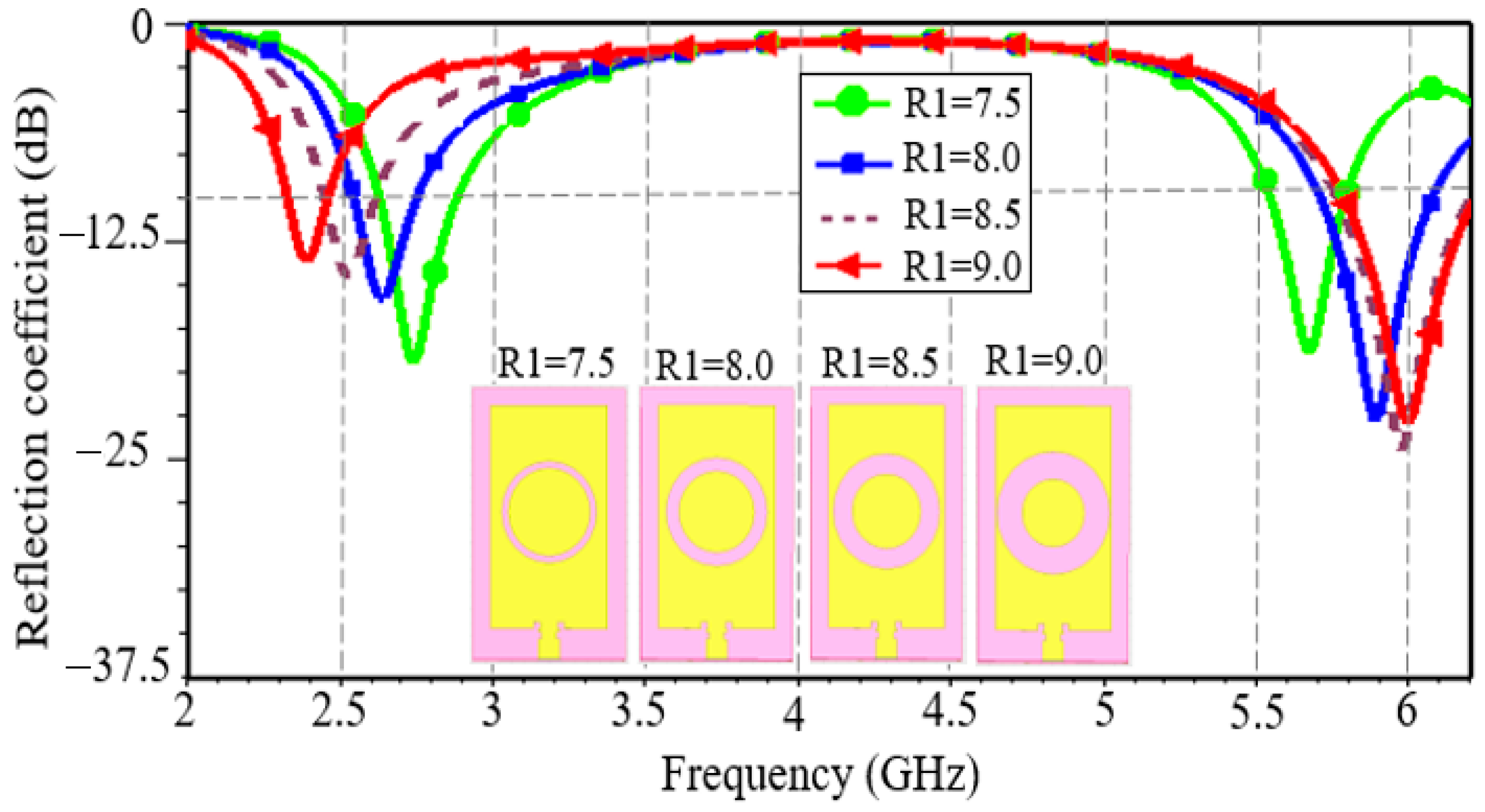
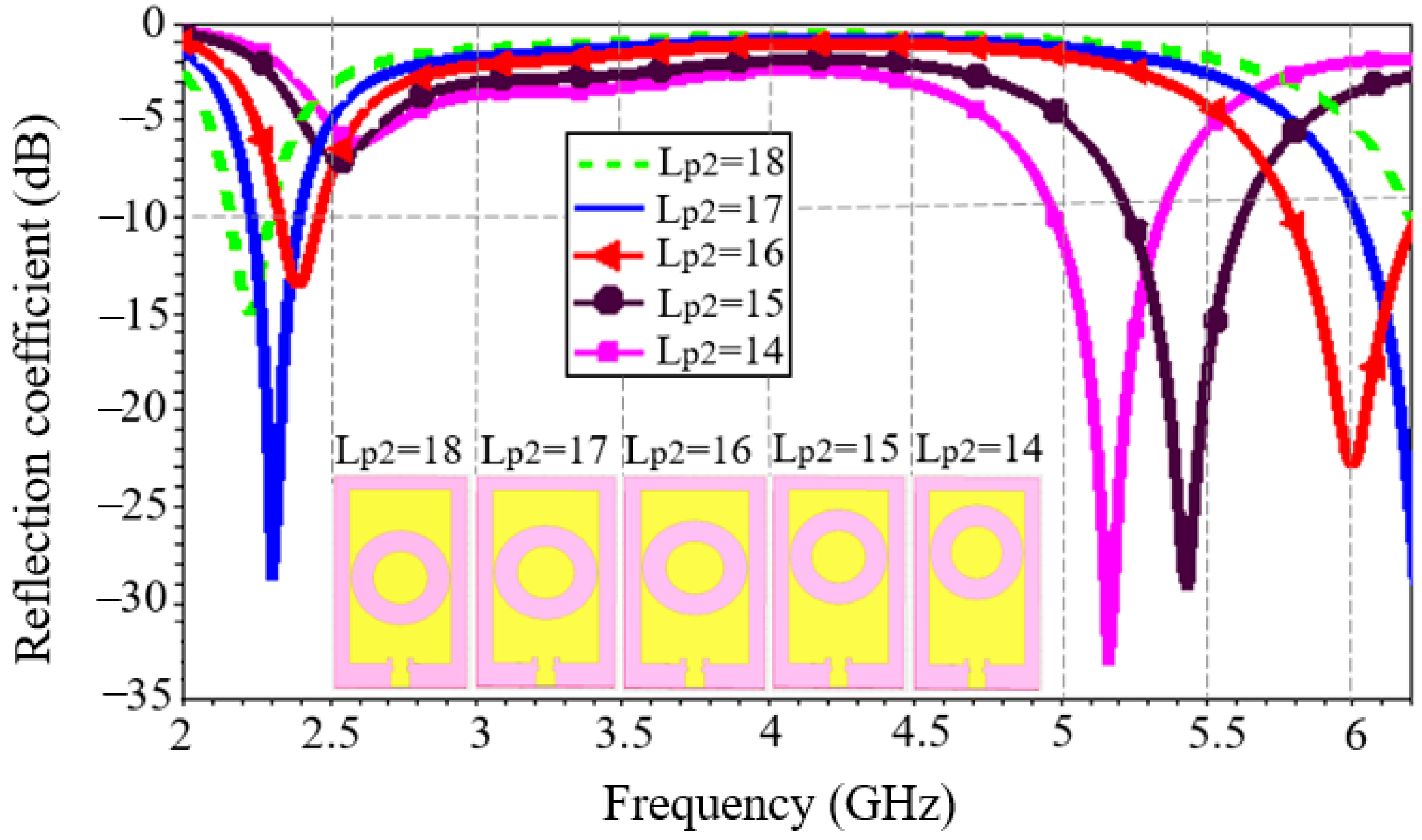
To study the impact of the ring’s dimensions on the reflection coefficient and the appearance of the second band observed, we assumed its fixed inner radius ( R 2 ) and varied its outer radius ( R 1 ) with a step of 0.5 mm. The reflection coefficient curve obtained is shown in Figure 4.
The insertion of the circular ring has enabled to obtain two frequency bands with a reflection coefficient of less than 10 dB. Furthermore, as R 1 increases, a frequency shift towards the 2.45 GHz band is observed. Finally, for R 1 = 9   m m (which almost represents the outer limit of the ring), the antenna exhibits center frequencies of 2.41 GHz and 6 GHz.
In the second step, we studied the impact of the ring’s vertical position on the reflection coefficient. We fixed the radius of the ring obtained previously ( R 1 = 9   m m and R 2 = 5   m m ) and varied the distance L P 2 in 1 mm increments to determine the best vertical position for the ring. Figure 5 shows the modulus of the reflection coefficient for different vertical positions of the ring. This study shows that, as the distance decreases, there is a shift from high frequency (6 GHz) to low frequencies with a reflection coefficient whose modulus decreases; on the other hand, at low frequency (2.45 GHz), there is a slight shift to high frequencies with an increasing S11. The opposite phenomenon is observed as L P 2 increases. In other words, as the slot moves closer to the feed line, both frequencies below 2.45 GHz and above 6 GHz appear. Frequencies very close to the desired frequencies are obtained for L P 2 = 16   m m . In conclusion, modifying the vertical position of a slot on the patch can contribute to improving the antenna’s reflection coefficient performance.
The insertion of the circular ring slot in step 2 would, therefore, have led to a new distribution and concentration of current at points on the radiating element, resulting in a frequency shift and a frequency very close to the desired second frequency.

3.2. Impact of Created Slots in Steps 3 and 4

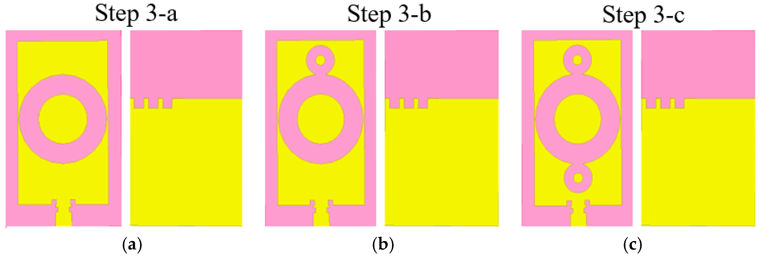
Figure 6 shows the various sub-steps involved in step 3 of the design. Step 3 consisted firstly (step 3-a) in modifying the upper part of the ground plane and maintaining the patch structure obtained in step 2, i.e., a radiating element with a circular ring slot with an outer radius R 1 of 9 mm and a position such that L P 2 is 16 mm. Two identical circular ring-shaped slots are then inserted symmetrically into the central ring in step 3-b and step 3-c, respectively.
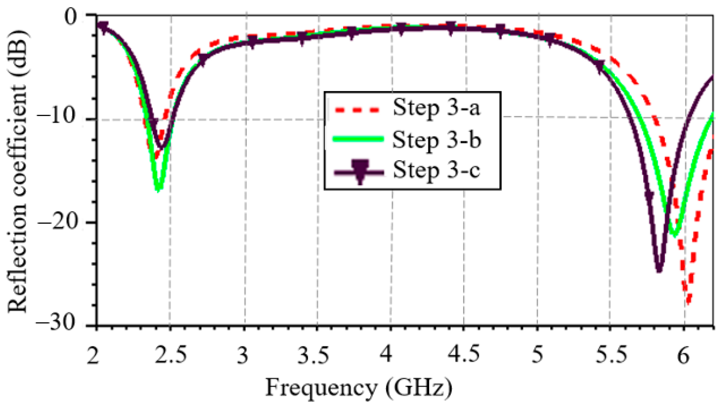
Figure 7 shows the evolution of the S11 in the various sub-steps shown in Figure 6. Firstly, the S11 improves after modification of the ground plane, compared with step 2 of the design ( 16.48 dB vs. 13.76 dB at 2.41 GHz and 27.96 dB vs. 23.25 dB at 6 GHz). Insertion of the ground plane slots, therefore, improved the reflection coefficient without allowing a frequency shift around the 6 GHz frequency. The circular rings, on the other hand, enabled this frequency shift, resulting in the desired second frequency being obtained at the end of step 3.
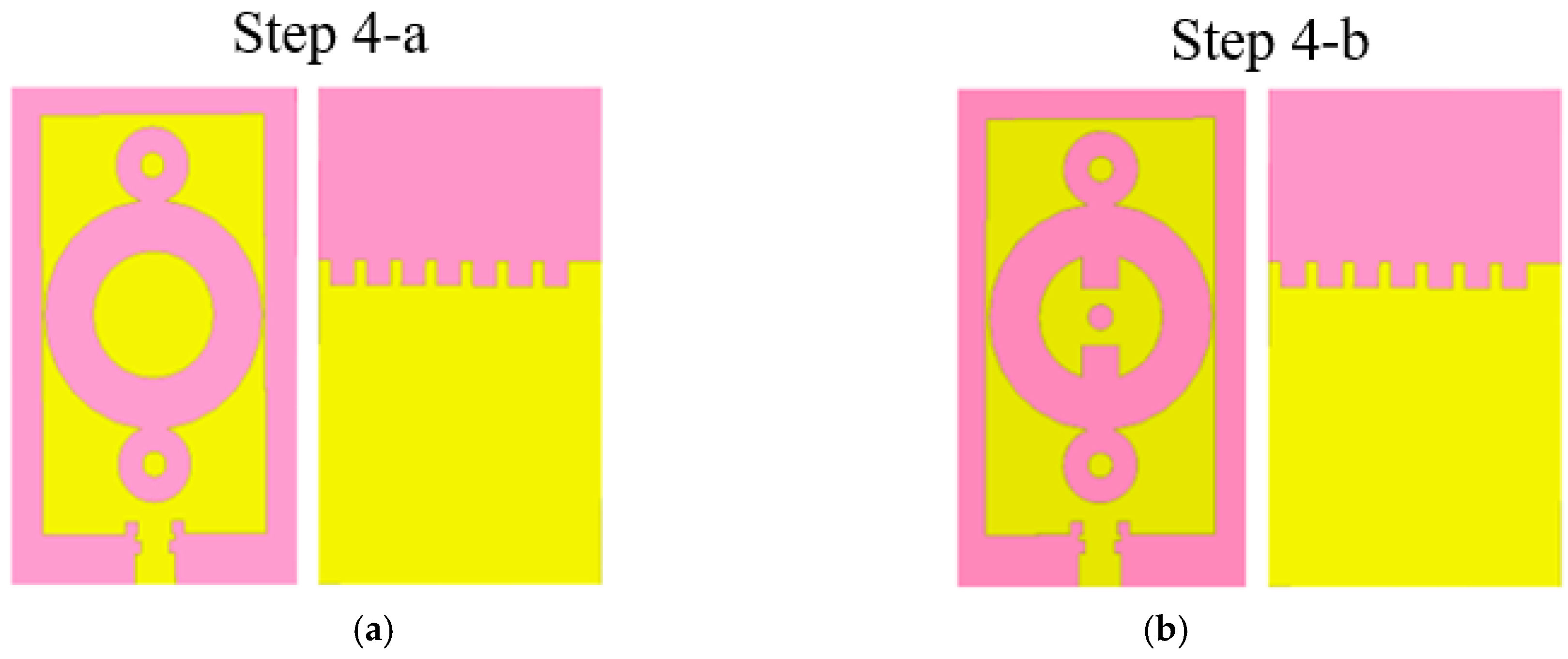
The positive influence of the ground plane slots on the S11 detected in step 3 made it possible to insert further slots to create a crenelated shape in the upper part of the ground plane, as shown in 
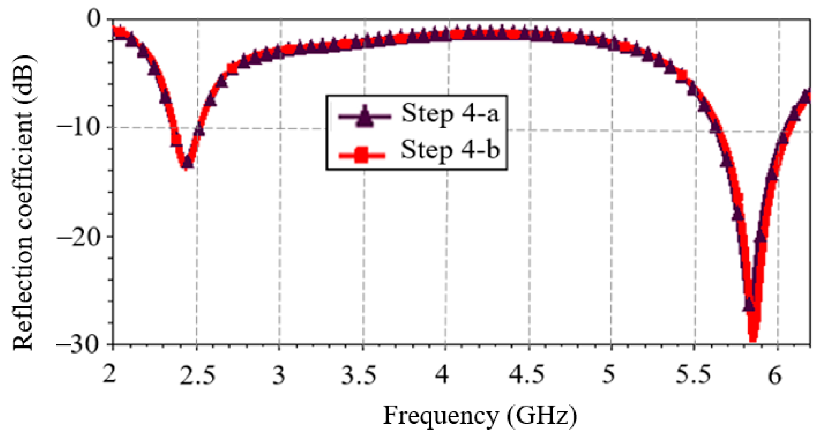
Figure 8a. The final optimization phase shown in Figure 8b involved adding slots inside the central ring. The study of the S11 is presented in Figure 9. The S11 has been improved in the 5.8 GHz band with the addition of the patch slots. Compared with step 3, the added slots improved the antenna’s S11 ( 13.82 dB vs. 12.79 dB at 2.4 GHz and 29.73 dB vs. 24.81 dB at 5.8 GHz) and bandwidth by 14%.
The improvement in antenna bandwidth can be justified by the shape and positioning of the slots. Indeed, these two parameters would have induced capacitive and inductive effects in the antenna, which would have increased its bandwidth.
In summary, the adjustments made to the ground plane and feed line had less effect than the slots on the patch. In fact, the patch slots made it possible to obtain two adapted ISM band frequencies and then also had an impact on performance parameters such bandwidth, gain, and radiation efficiency. Notches and slots on the ground plane and feed line increased the degree of freedom of the antenna’s performance parameters for optimization.
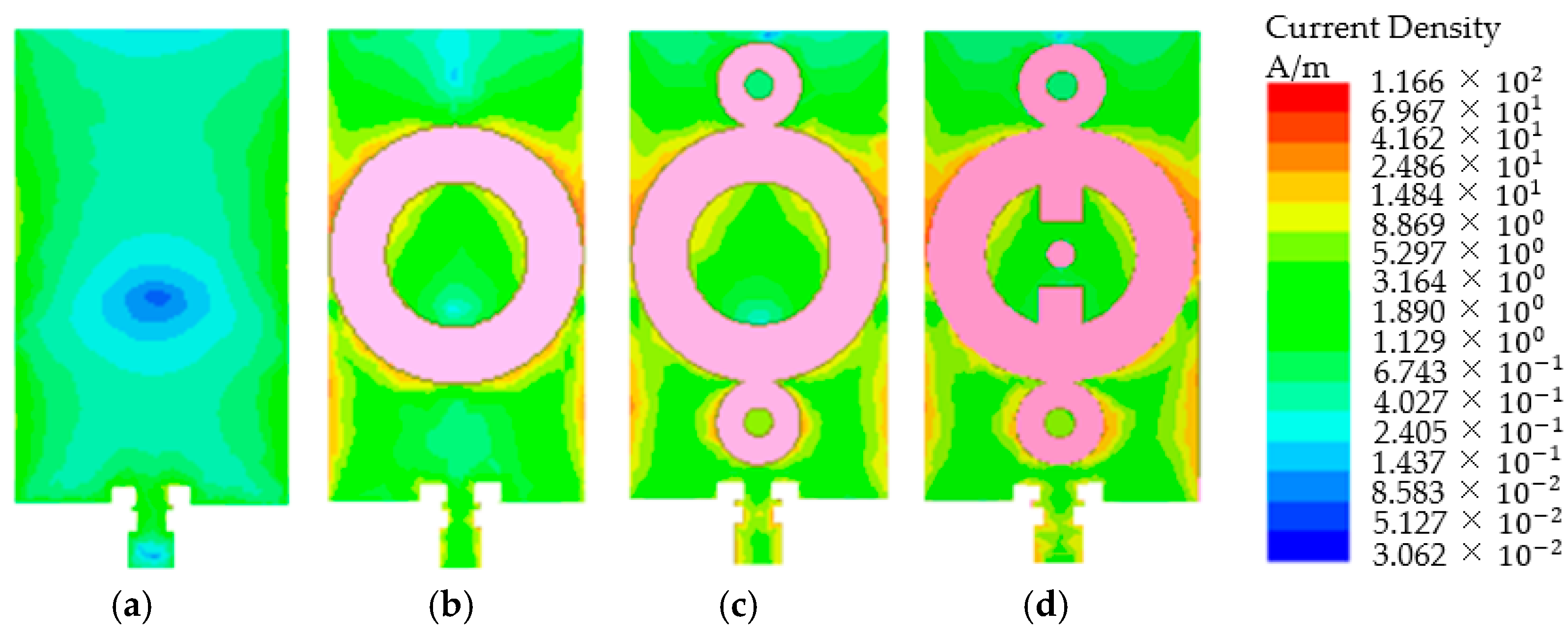
The observed reflection performance at the various steps of antenna design and the symmetry of the antenna can be justified by analyzing the surface current distribution on the patch. Figure 10 shows the current distribution in the 2.45 GHz band at the various steps of antenna design. Gradual intensification of the patch current surface distribution, particularly around the slots, is noted. No current is obviously observed in the slots. This shows that the surface current bypasses the slots. This current distribution on the patch is symmetrical. This observed symmetry is explained so by the symmetry of the antenna itself. Gradual intensification and symmetrical current distribution are also observed at 5.8 GHz. This current distribution explains why the slots on the patch were designed to improve the antenna’s performance. Another antenna performance parameter is its radiation efficiency.
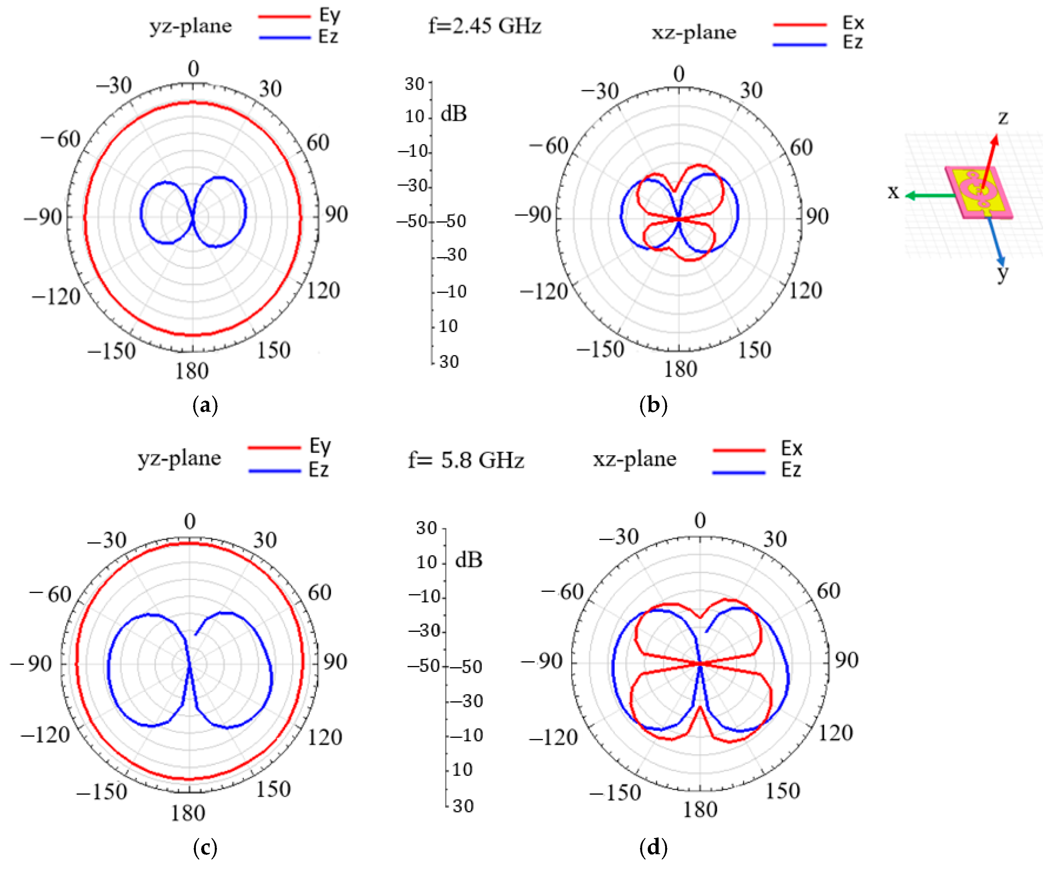
Simulated 2D electrical radiation patterns (in dB) for the two frequency bands in the E-plane (yz) and H-plane (xz) are shown in Figure 11. In both frequency bands, the co-polarized E-field is oriented along the y-axis (following the length of the feed line) and is maximal, reaching 20 dB at 2.45 GHz (Figure 11a) and 25 dB at 5.8 GHz (Figure 11c); also, it is (quasi)-omnidirectional. The cross-polarized E-field is oriented along the (xz) plane and is very weak, limited to 5 dB at 2.45 GHz (Figure 11b) and 0 dB at 5.8 GHz (Figure 11d).
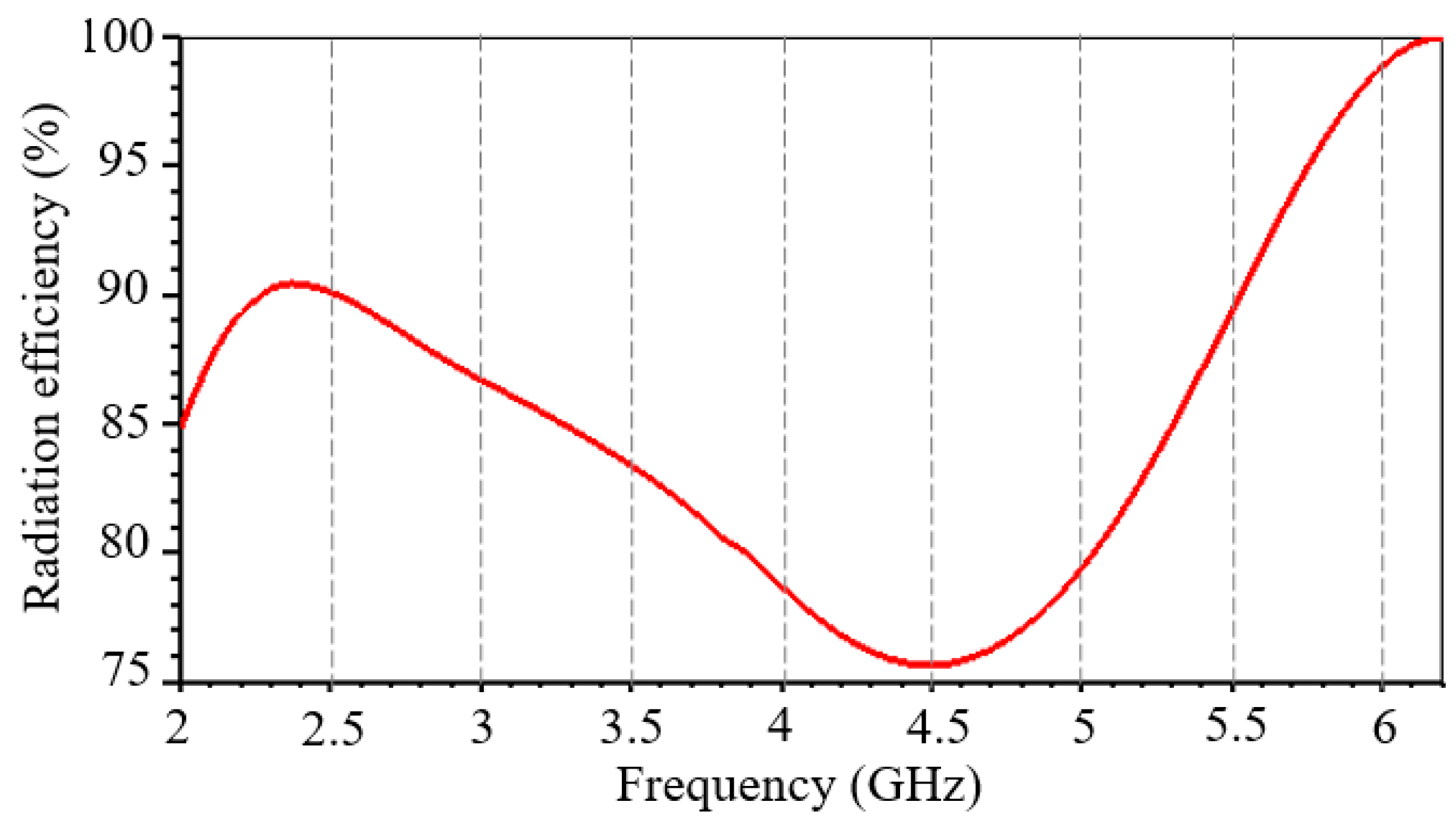
Figure 12 shows the antenna’s radiation efficiency as a function of frequency. The dual-band antenna has a radiation efficiency of 90.3% and 96.2% at 2.45 GHz and 5.8 GHz, respectively. In addition, the antenna reaches its maximum radiation efficiency around 2.45 GHz.

4. Experimental Results

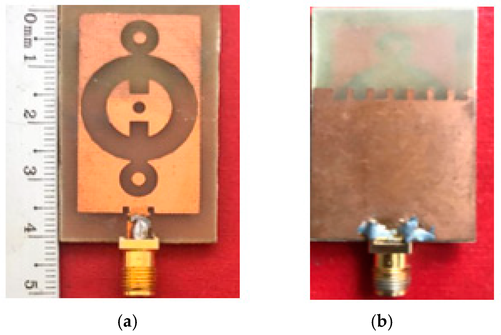
The proposed dual-band antenna is manufactured and experimentally characterized. Figure 13 shows a photo of the front and bottom view of the fabricated dual-band antenna.
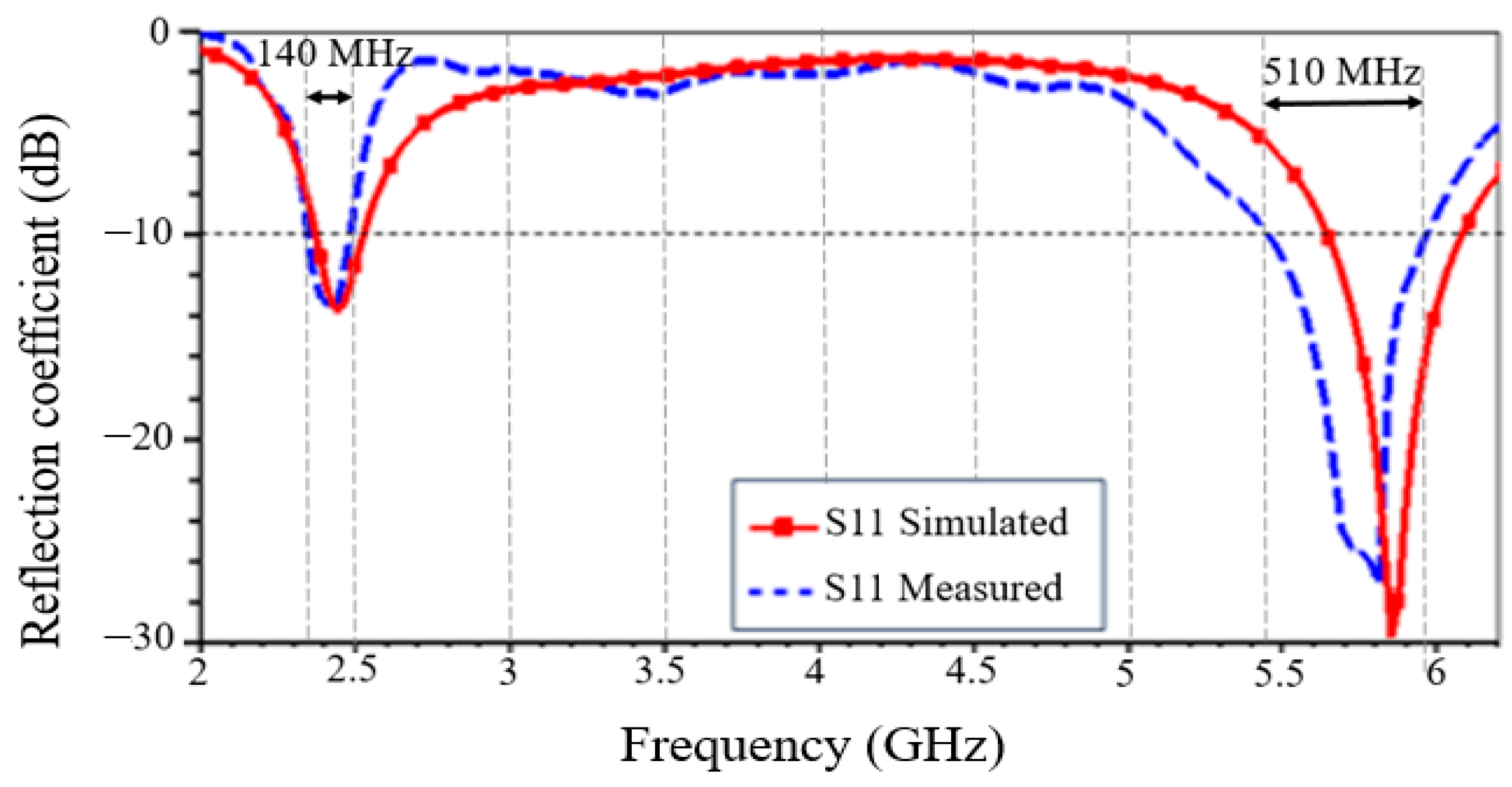
Figure 14 shows the simulated and measured reflection coefficient of the dual-band antenna as a function of frequency. The comparison results are detailed in Table 3. Measurement results show that the antenna operates at resonant frequencies of 2.44 GHz and 5.81 GHz. Relative to the modulus of the reflection coefficient, at 10 dB, a small frequency offset of 10 MHz and 40 MHz is, therefore, observed between measurements and simulation around the two ISM frequencies, respectively. In the 5.8 GHz band, the modulus of the measured reflection coefficient increases slightly, by 2.6 dB, while, in the 2.45 GHz band, it is almost constant. On the one hand, the slight frequency shift may be due to the slight modification of the characteristic impedance of the supply line after soldering of the SMA connector used during the manufacturing process. On the other hand, the slight decrease in the reflection coefficient observed at 5.8 GHz can also be explained by losses in the cables and in the SMA connector used. We also observe a 12.5% decrease and a 14.6% increase in bandwidth around the two frequency bands, respectively. These results show good agreement between simulation and measurement in terms of antenna matching at both frequency bands. There is a slight difference between the measured and simulated results, but the overall results agree well, validating the design as a whole.
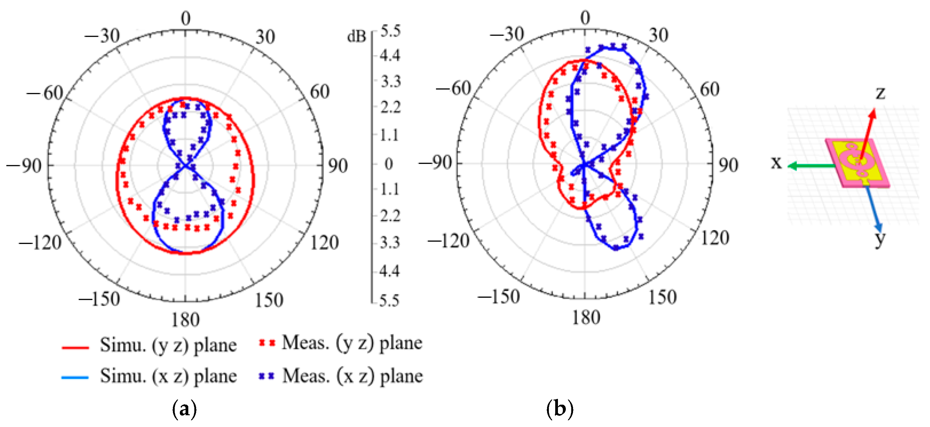
The simulated and measured antenna’s radiation patterns at the two frequencies are shown in Figure 15. At the frequency of 2.45 GHz (Figure 15a), the measured and simulated gains are 2.41 dB and 3.6 dB, respectively. In the band of 5.8 GHz, the measured gain is 5.22 dB vs. 5.09 dB simulated. Simulation and measurement show almost the same radiation pattern: quasi-omnidirectional in the E-plane (yz) and directional in the H-plane (xz).
In summary, the experimental measurements show that the antenna is dual-band and has the expected performances, i.e., (i) a reflection coefficient of less than 10 dB, (ii) a bandwidth of at least 100 MHz, (iii) a gain of at least 2 dBi, and (iv) an efficiency of at least 80% in both bands.
Several dual-band antennas operating in frequency bands of 2.45 GHz and 5.8 GHz have already been presented in the literature. Table 4 provides a comparative summary of the proposed antenna in terms of operating frequencies (Freq.), substrate parameters, patch type, dimensions, and antenna performance in terms of bandwidth (BW), gain, and radiation efficiency (Rad. Eff.) for each of the two frequency bands. The symbol “-” indicates that the corresponding value is not mentioned in the reference.
According to Table 4, the proposed dual-band antenna is very compact and performs well in terms of bandwidth, gain, and radiation efficiency. When compared with other antennas in the literature, the antenna proposed in this study has the smallest dimensions (although the orders of magnitude can be considered comparable) but also good performance in terms of gain for both frequency bands, particularly when the least expensive substrate, i.e., FR-4, is used. The antenna presented in [21] has a total volume of 2323 m m 3 (33% less compact) with low gains (1.48 dBi vs. 2.41 dBi and 3.83 dBi vs. 5.22 dBi). The article does not present the results in terms of bandwidth and efficiency. The antenna proposed in [23] has a total volume of 2880 m m 3 (46% less compact), slots with complex geometry (Sierpinski fractal geometry), similar gains, and higher bandwidths (48% on average), but the article does not present the results in terms of efficiency. Note also that the radiation efficiency obtained is high despite the use of a lossy FR-4 substrate and antenna compactness. This is due to its low relative permittivity (4.4) and low tangent losses (0.02), which improve not only radiation efficiency but also the antenna’s bandwidth at interest frequencies [16]. Consequently, the proposed dual-band antenna could, therefore, be a very good candidate both for wireless embedded and energy harvesting systems whose RF source operates in the 2.45 and 5.8 GHz bands.

5. Conclusions

This paper proposes a new dual-band antenna operating in the 2.45 GHz and 5.8 GHz bands. A detailed study of the design steps by simulation is made. Simulation results for antenna parameters have been compared with experimental measurements of the fabricated antenna. The manufactured antenna is compact, with dimensions of only 40 mm × 24 mm. It operates at resonant frequencies of 2.44 GHz and 5.81 GHz, with high bandwidths of 140 MHz and 510 MHz at these frequencies, respectively. The fabricated antenna gain is 2.41 dBi at 2.44 GHz and 5.22 dBi at 5.81 GHz. The antenna’s radiation efficiency is over 90%, reaching 96.2% at 5.81 GHz.
The proposed dual-band antenna offers good overall performance and is compatible with two ISM radiofrequency bands. Consequently, the proposed solution looks very promising for Bluetooth, WiFi, and WiMAX applications and can extend to recovering energy systems by exploiting RF waves in the two ISM bands.
An interesting prospect could be to combine this antenna with a dual-band energy recovery device, thus benefiting from both possible frequency options. Another possible option would be to exploit conventional MIMO-type techniques for information transmission: the dimensions and performance of the proposed antenna seem well-suited to this type of approach.

Author Contributions

Conceptualization, O.A.; methodology, O.A. and Y.D.; investigation, O.A. and A.B.; writing—original draft preparation, O.A.; writing—review and editing, O.A., A.B. and Y.D.; supervision, Y.D.; project administration, Y.D.; funding acquisition, Y.D. All authors have read and agreed to the published version of the manuscript.

Funding

This research received no external funding.

Institutional Review Board Statement

Not applicable.

Informed Consent Statement

Not applicable.

Data Availability Statement

The original contributions presented in this study are included in the article. Further inquiries can be directed to the corresponding author.

Conflicts of Interest

The authors declare no conflicts of interest.

References

  1. Edirisinghe, S.; Galagedarage, O.; Dias, I.; Ranaweera, C. Recent development of emerging indoor wireless networks towards 6G. Network 2023, 3, 269–297. [Google Scholar] [CrossRef]
  2. Huang, J.; Yu, S.; Kou, N.; Ding, Z.; Zhang, Z. Dual-band rectenna for wireless information and power transmission of WLAN applications. Prog. Electromagn. Res. M 2020, 96, 45–54. [Google Scholar] [CrossRef]
  3. Chetouah, F.; Aidel, S.; Bouzit, N.; Messaoudene, I. A miniaturized printed monopole antenna for 5.2–5.8 GHz WLAN applications. Int. J. RF Microw. Comput.-Aided Eng. 2018, 28, e21250. [Google Scholar] [CrossRef]
  4. Muhammad, S.; Tiang, J.J.; Wong, S.K.; Smida, A.; Ghayoula, R.; Iqbal, A. A Dual-band ambient energy harvesting rectenna design for wireless power communications. IEEE Access 2021, 9, 99944–99953. [Google Scholar] [CrossRef]
  5. Noor, F.S.M.; Zakaria, Z.; Lago, H.; Said, M.A.M. Design of dual-band aperture coupled antenna for energy harvesting applications. In Proceedings of the IEEE PES Asia-Pacific power and energy Engineering Conference, Kota Kinabalu, Malaysia, 7–10 October 2018. [Google Scholar] [CrossRef]
  6. Behera, B.R.; Mishra, S.K.; Alsharif, M.H.; Jahid, A. Reconfigurable antennas for RF energy harvesting application: Current trends, challenges, and solutions from design perspective. Electronics 2023, 12, 2723. [Google Scholar] [CrossRef]
  7. Singh, N.; Kanaujia, B.K.; Mainuddin, T.B.; Kumar, S.; Khan, T. A dual polarized multiband rectenna for RF energy harvesting. Int. J. Electron. Commun. 2018, 93, 123–131. [Google Scholar] [CrossRef]
  8. Chen, J.-H.; Cheng, C.-Y.; Chien, C.-M.; Yuangyai, C.; Chen, T.-H.; Chen, S.-T. Multiple performance optimization for microstrip patch antenna improvement. Sensors 2023, 23, 4278. [Google Scholar] [CrossRef] [PubMed]
  9. Guhaand, D.; Antar, Y.M.M. Microstrip and Printed Antennas: New Trends Techniques and Applications, 1st ed.; John Wiley and Sons: New York, NY, USA, 2011. [Google Scholar]
  10. Yadav, M.V.; Kumar, R.C.; Yadav, S.V.; Ali, T.; Anguera, J. A miniaturized antenna for millimeter-wave 5G-II band communication. Technologies 2024, 12, 10. [Google Scholar] [CrossRef]
  11. Yang, L.; Zhou, Y.; Zhang, C.; Yang, X.; Yang, X.X.; Tan, C. Compact multiband wireless energy harvesting based battery-free body area networks censor for mobile healthcare. IEEE J. Electromagn. RF Microwaves Med. Biol. 2018, 2, 109–115. [Google Scholar] [CrossRef]
  12. Citroni, R.; Mangini, F.; Frezza, F. Efficient integration of ultra-low power techniques and energy harvesting in self-sufficient devices: A comprehensive overview of current progress and future directions. Sensors 2024, 24, 4471. [Google Scholar] [CrossRef]
  13. Odiamenhi, M.; Jahanbakhsh Basherlou, H.; Hwang See, C.; Ojaroudi Parchin, N.; Goh, K.; Yu, H. Advancements and challenges in antenna design and rectifying circuits for radio frequency energy harvesting. Sensors 2024, 24, 6804. [Google Scholar] [CrossRef] [PubMed]
  14. Sharma, D.; Tiwari, R.N.; Kumar, S.; Sharma, S.; Matekovits, L. A compact wearable textile antenna for NB-IoT and ISM band patient tracking applications. Sensors 2024, 24, 5077. [Google Scholar] [CrossRef] [PubMed]
  15. Abu Damis, H.; Khalid, N.; Mirzavand, R.; Chung, H.-J.; Mousavi, P. Investigation of Epidermal Loop Antennas for Biotelemetry IoT Applications. IEEE Access 2018, 6, 15806–15815. [Google Scholar] [CrossRef]
  16. Alibakhshikenari, M.; Virdee, B.S.; See, C.H.; Abd-Alhameed, R.A.; Falcone, F.; Limiti, E. High-isolation leaky-wave array antenna based on CRLH-metamaterial implemented on SIW with ±30o frequency beam-scanning capability at millimetre-waves. Electronics 2019, 8, 642. [Google Scholar] [CrossRef]
  17. Simorangkir, R.B.; Yang, Y.; Matekovits, L.; Esselle, K.P. Dual-band dual-mode textile antenna on PDMS substrate for body-centric communications. IEEE Antennas Wirel. Propag. Lett. 2017, 16, 677–680. [Google Scholar] [CrossRef]
  18. Samal, P.B.; Chen, S.J.; Fumeaux, C. Flexible Hybrid-Substrate Dual-Band Dual-Mode Wearable Antenna. IEEE Trans. Antennas Propag. 2024, 72, 1286–1296. [Google Scholar] [CrossRef]
  19. Deng, X.; Yang, P.; Chen, S.; Ren, W. Design of a 2.4 & 5.8 GHz efficient circularly polarized rectenna for wireless power transfer applications. Electronics 2023, 12, 2645. [Google Scholar] [CrossRef]
  20. Boursianis, D.; Papadopoulou, M.S.; Koulouridis, S.; Rocca, P.; Georgiadis, A.; Tentzeris, M.M.; Goudos, S.K. Triple-band single-layer rectenna for outdoor RF energy harvesting applications. Sensors 2021, 21, 3460. [Google Scholar] [CrossRef] [PubMed]
  21. Bhatt, K.; Kumar, S.; Kumar, P.; Tripathi, C.C. Highly efficient 2.4 and 5.8 GHz dual-band rectenna for energy harvesting applications. IEEE Antennas Wirel. Propag. Lett. 2019, 18, 2637–2641. [Google Scholar] [CrossRef]
  22. Khan, W.A.; Raad, R.; Tubbal, F.; Mansour, G. Design of a compact antenna and rectifier for a dual band rectenna operating at 2.4 GHz and 5.8 GHz. In Proceedings of the 16th International Conference on Telecommunication Systems, Services, and Applications, Lombok, Indonesia, 13–14 October 2022. [Google Scholar] [CrossRef]
  23. Benyetho, T.; Zbitou, J.; El Abdellaoui, L.; Bennis, H.; Tribak, A. A new fractal multiband antenna for wireless power transmission applications. Act. Passiv. Electron. Compon. 2018, 2018, 2084747. [Google Scholar] [CrossRef]
  24. Shi, Y.; Jing, J.; Fan, Y.; Yang, L.; Wang, M. Design of a novel compact and efficient rectenna for Wi-Fi energy harvesting. Prog. Electromagn. Res. 2018, 83, 57–70. [Google Scholar] [CrossRef]
  25. Shi, Y.; Jing, J.; Fan, Y.; Yang, L.; Li, Y.; Wang, M. A novel compact broadband rectenna for ambient RF energy harvesting. Int. J. Electron. Commun. 2018, 95, 264–270. [Google Scholar] [CrossRef]
  26. Mansour, M.M.; Kanaya, H. Compact and broadband RF rectifier with 1.5 octave bandwidth based on a simple pair of L-section matching network. IEEE Microw. Wirel. Compon. Lett. 2018, 28, 335–337. [Google Scholar] [CrossRef]
  27. Shao, R.L.; Li, B.; Yang, L.; Zhou, Y.J. Electrically small multiband antenna based on spoof localized surface plasmons. EPJ Appl. Metamat. 2019, 6, 11. [Google Scholar] [CrossRef]
  28. Zeng, M.; Andrenko, A.S.; Liu, X.; Li, Z.; Tan, H.-Z. A compact fractal loop rectenna for energy harvesting. IEEE Antennas Wirel. Propag. Lett. 2017, 16, 2424–2427. [Google Scholar] [CrossRef]
  29. Wagih, M.; Hilton, G.S.; Weddell, A.S.; Beeby, S. Dual-band dual-mode textile antenna/rectenna for simultaneous wireless information and power transfer. IEEE Trans. Antennas Propag. 2021, 69, 6322–6332. [Google Scholar] [CrossRef]
  30. Pasha, M.I.; Kumar, C.; Guha, D. Application-friendly improved designs of single-fed circularly polarized microstrip antenna. IEEE Antennas Propag. Mag. 2019, 61, 80–89. [Google Scholar] [CrossRef]
  31. Georgiadis, A.; Andia, G.; Collado, A. Rectenna design and optimization using reciprocity theory and harmonic balance analysis for electromagnetic energy harvesting. IEEE Antennas Wirel. Propag. Lett. 2010, 9, 444–446. [Google Scholar] [CrossRef]
  32. Suh, Y.-H.; Chang, K. A high-efficiency dual-frequency rectenna for 2.45- and 5.8-GHz wireless power transmission. IEEE Trans. Microw. Theory Technol. 2002, 50, 1784–1789. [Google Scholar] [CrossRef]
  33. Musa, U.; Shah, S.M.; Majid, H.A.; Mahadi, I.A.; Rahim, M.K.A.; Yahya, M.S.; Abidin, Z.Z. Design and implementation of active antennas for IoT-based healthcare monitoring system. IEEE Access 2024, 12, 48453–48471. [Google Scholar] [CrossRef]
  34. Gao, G.-P.; Dou, Z.-H.; Yu, Z.-Q.; Zhang, B.-K.; Dong, J.-H.; Hu, B. Dual-mode patch antenna with capacitive coupling Structure for on-/off-body applications. IEEE Antennas Wirel. Propag. Lett. 2022, 21, 1512–1516. [Google Scholar] [CrossRef]
Figure 1. Proposed dual-band antenna optimized design: (a) top view of the feed line; (b) top view and (c) bottom view of the patch antenna.
Applsci 15 01912 g001
Figure 2. The design evolution of the proposed dual-band antenna in four steps. (a) Step 1: initial configuration with a partial ground plane; (b) step 2: configuration with slots insertion on the radiating element and feed line; (c) step 3: structure with two circular rings on the radiating element and slots partially in the upper part of the ground plane width; (d) step 4: final structure with slots in the central ring and a ground plane with a crenellated shape at the top.
Applsci 15 01912 g002
Figure 3. Simulated antenna reflection coefficient evaluation at four design steps.
Applsci 15 01912 g003
Figure 4. Simulated antenna reflection coefficient evaluation at different outer radius values.
Applsci 15 01912 g004
Figure 5. Simulated antenna reflection coefficient evaluation at different vertical ring positions.
Applsci 15 01912 g005
Figure 6. Sub-steps of the antenna design in step 3 with slots insertion on (a) the ground plane (step 3-a), (b) the upper part (step 3-b), and (c) the lower part (step 3-c) of the central ring of the radiating element.
Applsci 15 01912 g006
Figure 7. Simulated antenna reflection coefficient at different steps related to slot insertion on (step 3-a) the ground plane, (step 3-b) the upper part, (step 3-b), and the lower part (step 3-c) of the central ring of the radiating element.
Applsci 15 01912 g007
Figure 8. Sub-steps from antenna design to step 4 with (a) the creation of a complete slot shape across the width of the ground plane at step 4-a and (b) the insertion of slots inside the central ring at step 4-b.
Applsci 15 01912 g008
Figure 9. Simulated antenna reflection coefficients at step 4 with, at step 4-a, the creation of a complete slot shape across the width of the ground plane and, at step 4-b, the insertion of slots inside the central ring.
Applsci 15 01912 g009
Figure 10. Surface current distribution on the antenna patch at 2.45 GHz for (a) step 1, (b) step 2, (c) step 3, and (d) the optimized design step.
Applsci 15 01912 g010
Figure 11. The 2D simulated electrical radiation patterns of the final antenna: at 2.45 GHz, (a) E-Field in co-polarization (yz-plane), (b) E-field in cross-polarization (xz-plane), and, at 5.8 GHz, (c) E-Field in co-polarization (yz-plane) and (d) E-field in cross-polarization(xz-plane).
Applsci 15 01912 g011
Figure 12. Antenna radiation efficiency as a function of frequency.
Applsci 15 01912 g012
Figure 13. Dual-band antenna photography: (a) view from above and (b) bottom view.
Applsci 15 01912 g013
Figure 14. Measured and simulated reflection coefficient influence versus frequency.
Applsci 15 01912 g014
Figure 15. Simulated and measured antenna radiation pattern at (a) 2.45 GHz and (b) 5.8 GHz.
Applsci 15 01912 g015
Table 1. Dimensions of antenna geometrical.
Antenna
Parameters
Values
(mm)
Antenna
Parameters
Values
(mm)
Antenna
Parameters
Values
(mm)
Lsu40Lp19.2Lf30.5
Wsu24Lp216Lf41
Lpa33LS12.5Wf13.4
Wpa18.5Wf42.8Wf20.5
Lgr26Wp16.8Wf30.3
C13Wp210.3Wf51
C21Ws13Lg12
C31Ws22.1Wg13
R19Lf13Wg21
R25Lf21Wg32
Table 2. Dimensions of antenna geometrical.
StepsFrequency (GHz)S11 (dB)Bandwidth (MHz)
22.41
6
13.76
23.25
90
340
32.44
5.83
12.79
24.81
140
390
42.45
5.85
13.82
29.73
160
445
Table 3. Comparison of measured and simulated reflection parameters and bandwidth.
ToolCentral Frequency
(GHz)
S11
(dB)
Bandwidth   at   10 dB (MHz)
Simulation2.45
5.85
13.66
29.73
160
445
Experimental measurements2.44
5.81
13.60
27.12
140
510
Table 4. Comparative study of the antenna’s performance with the literature.
Ref.Freq.
(GHz)
SubstrateAntenna ShapeAntenna Size
(mm × mm × mm)
BW
(MHz)
Gain
(dBi)
Rad. Eff.
(%)
[17]2.45
5.8
PDMSMonopole-84
247
4.16
4.34
-
[18]2.45
5.8
PDMS/PF4-foamMonopole62 × 62 × 3.6200
300
4.90
3.5
68
81
[19]2.4
5.8
Rogers
RO4350B
Microstrip slot45 × 45 ×1.524320
3730
3.5
6.2
-
[21]2.4
5.8
FR-4Monopole44 × 33 × 1.6-1.48
3.83
-
[22]2.4
5.8
RT/duroid 5880Monopole 40 × 35 × 1.6 -3.6
3.3
-
[23]2.4
5.8
FR-4Microstrip slot60 × 30 × 1.6510
680
2.2
5.8
-
[32]2.45
5.8
RT/duroid 5870Dipole126.7 × 45 × 0.5-5
5.4
-
[33]2.4
5.8
Rogers
RO3003
Microstrip slot44 × 41 × 1.5289
300
4.82
5.75
90.1
87.4
[34]2.4
5.8
PDMSMicrostrip slot- 90
330
2.3
6.67
-
This work2.44
5.81
FR-4Microstrip slot40 × 24 × 1.6140
510
2.41
5.22
90.3
96.2
Disclaimer/Publisher’s Note: The statements, opinions and data contained in all publications are solely those of the individual author(s) and contributor(s) and not of MDPI and/or the editor(s). MDPI and/or the editor(s) disclaim responsibility for any injury to people or property resulting from any ideas, methods, instructions or products referred to in the content.

