Article

Research on the Diffusion and Deposition Characteristics of Refrigerant Under Vertical Upward Leakage in a Confined Space

1
Zhejiang Zhongguang Electrical Co., Ltd., Lishui 323000, China
2
Zhejiang Key Laboratory of Refrigeration and Cryogenic Technology, Institute of Refrigeration and Cryogenics, Zhejiang University, Hangzhou 310007, China
*
Author to whom correspondence should be addressed.
Appl. Sci. 2025, 15(4), 1918; https://doi.org/10.3390/app15041918
Submission received: 29 December 2024 / Revised: 5 February 2025 / Accepted: 10 February 2025 / Published: 12 February 2025
(This article belongs to the Section Energy Science and Technology)

Abstract

:
In a confined space, the flammability of alternative refrigerants (such as R717, R290, R32, and R1234yf) poses significant safety risks during leaks. However, in the actual refrigeration systems, the direction of refrigerant leakage is difficult to predict, complicating explosion risk assessment. In this work, R717, R290, R32, and R1234yf were selected as the research objects to analyze the diffusion process and deposition characteristics of different refrigerants leaking vertically upward into a confined space, and to explore the migration characteristics of flammable refrigerants under different leakage amounts and flammability area in a confined space. The results show that after vertical upward leakage, the refrigerants tend to impact the top wall and then move along the top wall away from the leak source. High-density refrigerants diffuse primarily near the floor, while less dense refrigerant diffuses along the top and side wall of the space. After the refrigerant leakage stops, R1234yf, with the highest density, exhibited the most pronounced deposition, with the highest concentration near the floor and the lowest at the top (1.69% and 0.7%, respectively). Conversely, lower-density refrigerants showed decreasing floor concentrations and increasing top concentrations, with reduced overall deposition. Compared to the deposition concentration of R290 at the bottom of the room (1.32%), R744 demonstrated higher deposition near the floor than R290, likely due to its higher viscosity at similar densities. In addition, using R290 as an example, the study reveals that the increase in leakage amount and the prolonged time result in a gradual expansion and upward diffusion of the flammability area, encompassing the top of the space, walls, and floor.

1. Introduction

The refrigeration and air conditioning industry has witnessed significant growth in recent years, driven by the growing demand from various sectors in the Chinese and global markets. This growth can be attributed to factors such as urbanization, improved living standards, and the increasing demand for precise temperature control in industrial environments. The industry is expected to continue its upward trend in the foreseeable future [1]. The wide application of refrigeration and air conditioning systems causes large amounts of refrigerant to be consumed every year. Most of the refrigerants used in refrigeration systems today have very high global warming potentials and long atmospheric lifetimes. Refrigerant leaks can occur throughout the lifecycle of a refrigeration system, from scrapping to use and maintenance. These leaks can be attributed to various factors, including corrosion inside the pipeline, ant nest corrosion between the outer wall of the pipeline and the atmospheric environment, loosening of small components inside the system, improper external operation, etc. [2,3]. These leaks release greenhouse gases into the atmosphere, contributing to significant environmental harm [2,4]. To mitigate greenhouse gas emissions, a series of regulations and agreements have been implemented. The Kigali Amendment to the Montreal Protocol, for instance, designates 18 hydrofluorocarbons (HFCs) as controlled substances [5]. This requires developing countries, including China, to initiate a phase-down starting in 2024. From 2029 onwards, HFC production and consumption will be frozen at baseline levels, followed by a gradual reduction [6]. Furthermore, the EU’s F-Gas Regulation, with amendments effective from March 2024, prohibits the use of refrigerants with a Global Warming Potential (GWP) exceeding 150 in single air conditioning and heat pump systems from January 2025. For split air conditioners and heat pumps with refrigerant charges below 3 kg, the GWP of fluorinated greenhouse gases must be less than 750. From 2035, split air conditioners and heat pumps with capacities up to 12 kW, as well as chillers with capacities up to 12 kW, will be prohibited from using fluorinated greenhouse gases, and their GWP must be below 150 [7]. These regulations necessitate a transition towards refrigerants with a lower environmental impact. Natural refrigerants and mixed refrigerants offer promising alternatives, demonstrating superior environmental performance and significant application potential in household air conditioning and heat pump systems [8,9,10]. For example, hydrocarbon refrigerants such as R600a are widely used in small refrigerators [11], while R717, ammonia, finds applications in large cold storages and exhibits strong potential in heat pumps and smaller-scale cold storage systems [12]. Propane (R290) is considered a highly promising alternative for automotive heat pump systems [13] and for residential air conditioning systems [14,15]. Additionally, R1234yf-containing refrigerant mixtures show significant potential as alternatives in various refrigeration and air conditioning applications [6]. However, refrigerant leaks during the operation of a refrigeration system have detrimental consequences. Firstly, they can significantly impact system performance and efficiency [16]. Secondly, they pose significant safety hazards to the surrounding environment [17,18]. For example, flammable refrigerants, when released into confined spaces, can accumulate in localized areas. If the refrigerant concentration exceeds the lower flammability limit, an explosion can occur, posing a severe safety risk. Therefore, investigating the diffusion and distribution characteristics of refrigerant leaks within confined spaces is crucial. Analyzing the migration characteristics and boundaries of the flammability area during the leakage process is essential for ensuring the safe application of flammable alternative refrigerants in refrigeration and air conditioning systems.
Extensive research on refrigerant leakage and diffusion has been conducted by domestic and foreign scholars, encompassing both theoretical and experimental approaches. In terms of theory, Li et al. [19] comprehensively investigated the refrigerant leakage within pipelines and its subsequent diffusion in confined spaces. They developed a leakage–diffusion model for real refrigerant gases, dividing the leakage process into three stages: transportation, primary throttling, and secondary expansion. The diffusion process within the confined space was similarly categorized into two stages: localized expansion and compression near the leak source, followed by turbulent diffusion in the far field. By incorporating the thermophysical properties of real refrigerants, the model reveals that transonic flow conditions are reached during the throttling and expansion phases. Upon entering the external space, the refrigerant continues to expand and compress, generating complex excitation waves within the near-field region. These waves, forming Mach loops, induce substantial variations in the temperature, pressure, and velocity of the refrigerant. The presence of the Mach ring hinders efficient refrigerant diffusion, significantly increasing the localized high-concentration areas formed by the leaked refrigerant. Based on their previous work, Li et al. [20,21] explored the effects of the initial leakage pressure, leakage hole diameter and hole shape, refrigerant thermophysical parameters, velocity, and concentration fields after refrigerant leakage. The diffusion process and concentration distribution characteristics of the refrigerant in the confined space were analyzed, and the boundaries of the flammability area where the refrigerant leaked into the confined space under different conditions were divided. It was found that due to the differences in the thermophysical properties of the refrigerant, the temperature field, velocity field, and concentration field in a confined space showed large differences. Among them, the density, viscosity, and diffusion coefficient of the refrigerants were found to have a significant effect on the concentration field. When two refrigerants have similar densities, the Schmidt number (Sc) can be used to comprehensively evaluate the combined effects of viscosity and diffusion coefficient on their diffusion. In addition, Maojuan et al. [22] numerically simulated the diffusion process of R290 when it leaks from the heat exchanger elbow in the indoor unit of a split air conditioner and analyzed the refrigerant concentration distribution within the room. Elatar et al. [23] simulated the scenario of R32 leaking from the indoor heat exchanger in a rooftop air conditioning system, and found that the refrigerant concentration in most areas of the air supply duct exceeded the flammability limit. Colbourne et al. [24] studied several of these parameters, including refrigerant charge size, leakage mass flow, leakage direction, height of refrigerant-containing components, cabinet doors, condensing unit housings, air flow, and room clogging, by simulating R290 leaks. The simulation results were used to understand the meaning of device leaks and possible structural characteristics that help limit the development of high concentrations. Liu et al. [25] studied the R290 leakage scenario in a multi-split air conditioning system, analyzing the variations in refrigerant concentration under different ventilation conditions within the confined space. Ram et al. [26] performed CFD simulations of the dispersion of HC-290 leaks for a variety of scenarios, including leakage rate, IDU installation height, IDU fan on or off, and furniture type. Papas et al. [27] used computational fluid dynamics to simulate major leaks from a 2640 kW (750TR) chiller, evaluating a range of refrigerant leak rates and different alarm trigger ventilation rates to understand the dilution requirements to prevent a significant fuel buildup.
Experimental investigations into refrigerant leakage and diffusion have also been conducted extensively. Tang et al. [28] conducted a very comprehensive study on the concentration changes of R290 after it leaked in household split air conditioners and air-cooled heat pump units. They analyzed the impact of various factors, including refrigerant charge, indoor unit size, leakage hole diameter, airflow intensity within the space, heat pump system placement, and leakage hole height, on the resulting refrigerant concentration distribution. It was found that the refrigerant would transfer from the outdoor unit to the indoor unit after the air conditioner was shut down in the cooling mode. To mitigate this risk, they proposed installing solenoid valves on the liquid connection pipelines of both the indoor and outdoor units. Additionally, a high concentration area primarily formed within the system itself and in the immediate vicinity above the ground surrounding the system. Based on Tang’s work, Ning et al. [29] conducted an ignition experiment on R290 leaks from a split-type air conditioner indoor unit to assess the associated fire risk. It was found that during the experiment, the infrared gas concentration detector detected that the concentration of the refrigerant in the local area had not yet reached the lower flammability limit. Zhang et al. [30] conducted an experimental study on the concentration distribution of R290 after leaking from a split air conditioner indoor unit, investigating the concentration distribution of refrigerant explosion. The results demonstrated that explosions can occur within the formed explosion area when encountering an ignition source. Patel et al. [31] conducted a project in two phases with the aim of testing several heating, ventilation, air conditioning, and refrigeration systems for refrigerant leakage under operating conditions representative of real-world applications to record the changes in the pressure decay rate and mass flow rate of leaking refrigerant over time. Oreilly et al. [32] evaluated the risk of refrigerant leakage in reefer containers and conducted leakage experiments in different scenarios. Jin et al. [33] conducted a study on the concentration distribution of R32 following leakage in a split air conditioner, while Zhang et al. [34] conducted an experimental study on the concentration distribution of R290 leaking into the passenger compartment in an automobile air conditioning system.
A review of the literature indicates that domestic and foreign researchers have developed extensive research on the diffusion process, concentration distribution, and explosion characteristics of leaked refrigerants within confined spaces. However, in most of the existing work, the direction of refrigerant leakage has not been studied as a significant influencing factor. In actual refrigeration systems, the potential leakage points are inherently random, leading to a diverse leakage direction. When refrigerant leaks into a confined space from different directions, the diffusion process of the refrigerant in the confined space and the distribution and migration characteristics of the flammability area are greatly influenced by the leakage direction. While previous studies have investigated vertical downward and horizontal leakage scenarios [19,20], the unique characteristics of vertically upward leakage remain largely unexplored. The existing conclusions are insufficient to predict the resulting spatial distribution of high-concentration areas following vertically upward refrigerant leakage. Based on the above reviews, the diffusion process and deposition characteristics of four refrigerants (R717, R290, R32, and R1234yf) undergoing vertically upward leakage into a confined space were investigated in this work. The main aims of this work were to analyze the influence of refrigerant’s physical properties on the resulting concentration distribution and to explore the migration characteristics of the flammable refrigerant within the flammability area under varying leakage amounts.

2. Development of the Numerical Model

2.1. Governing Equations

In the previous work, the real refrigerant leakage diffusion model proposed by Li et al. [19] regarded the leakage of high-pressure gas refrigerant in the pipeline as three stages, as shown in Figure 1: (1) Point 0 to point 1 is the gas transport process in the pipeline; (2) point 1 to point 2 is the process of gas leakage from the inside of the pipeline to the outside space through the leakage hole; (3) point 2 to point 3 is the process of the leaking high-pressure gas expanding from the inner wall of the pipeline to the outside world. The diffusion process after refrigerant leakage can also be divided into two stages: In the first stage, due to the high initial pressure in the pipeline of the refrigeration system, the pressure of the refrigerant gas at the leakage hole on the outer wall of the pipeline when leakage occurs is higher than the atmospheric pressure, and the leaking refrigerant gas will continue to expand and compress, which can be described by the mass, momentum, and energy conservation equations, respectively. In the second stage, the expansion and compression processes disappear, and the leaking refrigerant gas has returned to room temperature and normal pressure states. Regardless of the heat transfer between the leaking gas and the external environment, it can be considered as a single turbulent motion process, which can be described by the mass and momentum conservation equations. At the same time, the leaking refrigerant gas will be continuously mixed with the air, and the diffusion flux of the refrigerant gas is calculated using the component transport equation.
In fact, after the high-pressure refrigerant gas in the pipeline leaks, there will be a continuous expansion and compression process in the near-field area below the leak hole, and the temperature, pressure, and speed of the refrigerant will undergo very drastic changes. As the refrigerant spreads to the far field, the refrigerant gradually returns to the room temperature and atmospheric pressure state. The improved model has good applicability in describing the expansion process and multi-field coupling such as pressure field and velocity field after the leakage of high-pressure gaseous refrigerant. The accuracy and reliability of this model have been verified in experiments [19].
After the high-pressure refrigerant gas in the pipeline leaks, a series of continuous expansion and compression processes occur in the near-field area below the leakage point. This results in significant fluctuations in the refrigerant’s temperature, pressure, and velocity. As the refrigerant diffuses into the far-field region, it gradually equilibrates with the ambient temperature and pressure.
During the high-speed jet flow in the near-field, shock waves can form within the flow domain, necessitating the use of a highly refined grid and extremely small-time steps for accurate numerical capture. This study primarily focuses on the diffusion process and deposition characteristics of the refrigerant in the far-field region.
To simplify the computational analysis, the numerical model adopts an initial condition where the refrigerant has already equilibrated to room temperature and ambient pressure. The diffusion of the refrigerant in the far-field region is then simulated by solving the governing equations for turbulence and component transport. In addition, we define conditions such as refrigerant inlet flow through UDF. These governing equations are as follows.
(1)
Continuity equation
ρ t + x j ρ u j = 0
where ρ is the density of the mixed gas (kg/m3); u j is the time-averaged velocity of the gas flowing in three directions ( u x , u y , u z , m/s).
(2)
Momentum conservation equation
ρ u i t + x j ρ u i u j = p x i + x j μ t u i x j + x j μ t u j x i + ρ ρ a g i
where p is the absolute pressure (Pa); μ t is the turbulent viscosity (Pa · s); g i is acceleration due to gravity (m/s2).
(3)
Energy conservation equation
( ρ T ) t + x j ρ u j T = 1 c p x j k t T x j + c p v c p a c p μ t σ c J x j T x j
where T   i s   t h e   t i m e a v e r a g e d   t e m p e r a t u r e   o f   t h e   f l u i d K ;   k t is the turbulent thermal conductivity (W/(m·K)); c p v is the constant pressure specific heat capacity of the leaking refrigerant (J/(kg·K)); c p a is the constant pressure specific heat capacity of air (J/(kg·K)); σ c is the turbulent Schmidt number.
(4)
Component transport equation
( ρ J ) t + x j ρ u j J = x j ρ D t J x j
where J is the time-averaged mass fraction of the component; D t is the turbulent diffusion coefficient of the fluid (m2/s).
(5)
Turbulence models
Turbulent kinetic energy k equation:
( ρ   k ) t + x j ρ   u j k = x i k k x i + G k + G b Y k
Turbulence dissipation rate ε equation:
( ρ   ε ) t + x j ρ   u j ε = x i ε ε x i + G ε + G ε b Y ε
where G k represents the turbulent kinetic energy generated by the time-averaged velocity; k and ε represent the effective diffusivity of k and ε, respectively; Y k   a n d   Y ε represent the dissipation of k and ε under the action of turbulence, respectively. G b and G ε b represent the turbulent kinetic energy and turbulent dissipation rate generated by buoyancy, respectively.

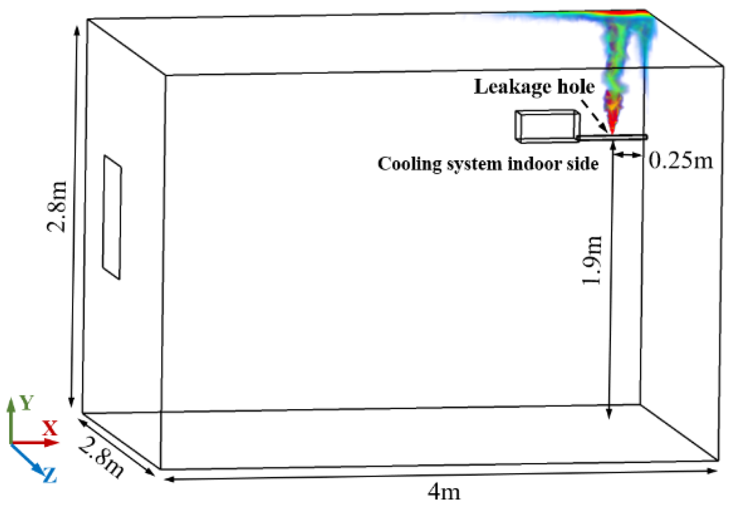
2.2. Geometric Models

The geometric model established in this work is shown in Figure 2. The size of the confined space is 4 m × 2.8 m × 2.8 m. The leakage hole appears on the gas phase pipeline connecting the indoor unit and the outdoor unit of the refrigeration system. The leakage hole is assumed to be circular with a diameter of 3 mm, the height of the leakage hole is 1.9 m, the distance from the leakage hole to the xy wall is 0.115 m, the distance from the leakage hole to the zy wall is 0.25 m, the confined space is a non-ventilated environment with closed doors and windows, and the refrigerant is leaking vertically upwards. In addition, to simplify the calculation, other assumptions given in this paper are as follows:
(1)
The refrigerant leakage process is regarded as the leakage of gaseous refrigerant, and the physical properties of the leaking refrigerant are calculated using the physical properties at room temperature (25 °C) and atmospheric pressure (0.1 MPa);
(2)
The leakage process is regarded as uniform leakage, and the leakage rate is the average rate of the working medium in the leakage process.
Figure 2. Spatial model of vertical upward leakage situation.
Applsci 15 01918 g002
The refrigerant leakage and diffusion processes were simulated using ANSYS 2021 R1 software. The study focused on four refrigerants: R717, R290, R32, and R1234yf. For comparative analysis, R22 and R744 were also included. (The viscosity of R22 and R32 is close, and the density of R290 and R744 is close, which is conducive to better analysis of the influence of the refrigerant’s physical parameters on the diffusion process and concentration distribution of the refrigerant after leakage into a limited space in the vertical upward direction). The physical parameters of the refrigerant are shown in Table 1.
At the same time, the refrigerant is regarded as a compressible ideal gas, and the leakage rate of the refrigerant leakage process is further determined. Based on the real refrigerant leakage diffusion model established by Li et al. [18], the saturation pressure corresponding to different refrigerants at room temperature and the leakage rate at a 3 mm aperture were calculated. The calculation results are shown in Table 2. While the actual leakage rate varies slightly for different refrigerants under the same aperture size and room temperature conditions, the purpose of this paper is to investigate the differences in the diffusion and deposition characteristics of different refrigerants under the same leakage. A constant flow rate of 1.2 g/s that can be achieved by all the refrigerants in this paper during the leakage process was selected to facilitate the comparative analysis of the diffusion and deposition characteristics.

2.3. Numerical Methods

In the setting of the boundary conditions, this paper uses the refrigerant restored to room temperature and atmospheric pressure as the initial condition of the numerical model, and sets the initial temperature and initial pressure of the refrigerant as the ambient temperature and atmospheric pressure, 298.15 K and 101.3 kPa. The model entrance was set as the mass flow entrance, the mass fraction of the working medium at the leakage port was 1, and the turbulence intensity was 5%. The model outlet was set to the pressure outlet. All the other boundaries in the room were set to the wall conditions. The turbulence model uses the standard k-ε turbulence model. The SIMPLE algorithm coupling pressure and velocity is used to solve the equation. The scalar variables in the model are discretized using the second-order windward scheme, and the calculation result of the transient model convergence accuracy transient time step was set to less than 10−3 s.

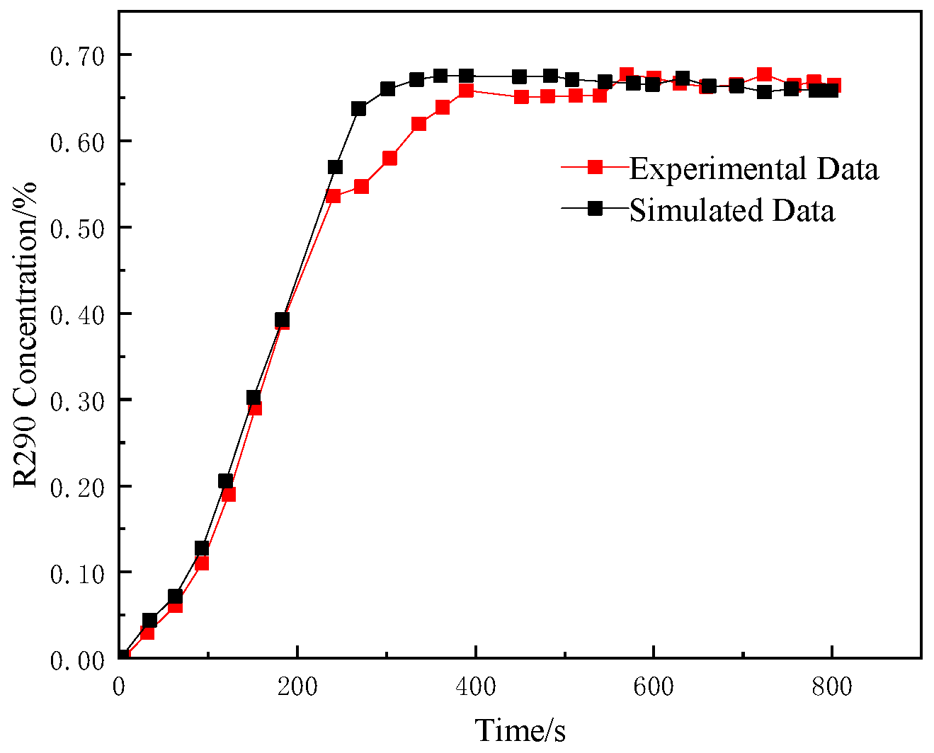
2.4. Grid Independence and Experimental Verification

The geometric model was meshed using an unstructured grid, and the reliability of the model was verified through grid independence verification, and a comparison with the experimental data from the literature [18] was conducted to ensure the reliability of the gas leakage model.
In this paper, the physical model used was divided into five mesh sizes, and the mass fraction was selected as the index to verify the grid independence. The verification results are shown in Figure 3. Considering the accuracy of calculation and running speed, grid N = 600,119 was selected. In order to ensure the accuracy and reliability of the simulation, the grid near the leak hole was locally encrypted, and the boundary layer was set on the inner wall of the leak pipeline through which the refrigerant flowed. The mesh size at the leak hole was 0.0001 m, the mesh size of the space was 0.08 m, and the mesh quality was 0.847.
The physical model was validated against the experimental data from Zhang et al. [29] (Figure 4). Using an R290 leakage experiment with a refrigerant mass flow rate of 0.0018 kg/s, the simulated and measured concentration changes at the measuring point showed good agreement in regard to both trend and magnitude, with the final R290 concentration stabilizing between 0.6% and 0.8%.

3. Results and Discussion

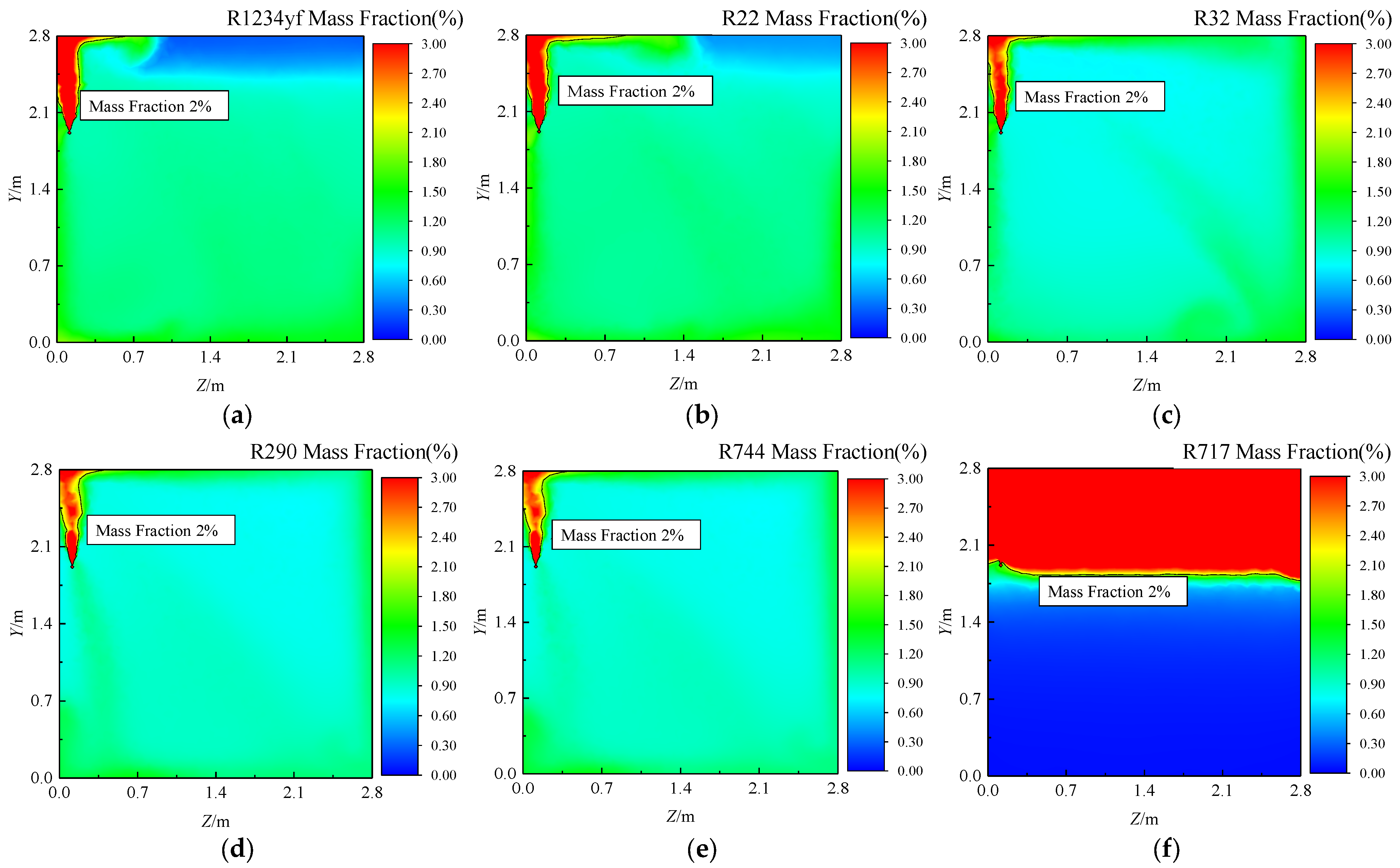
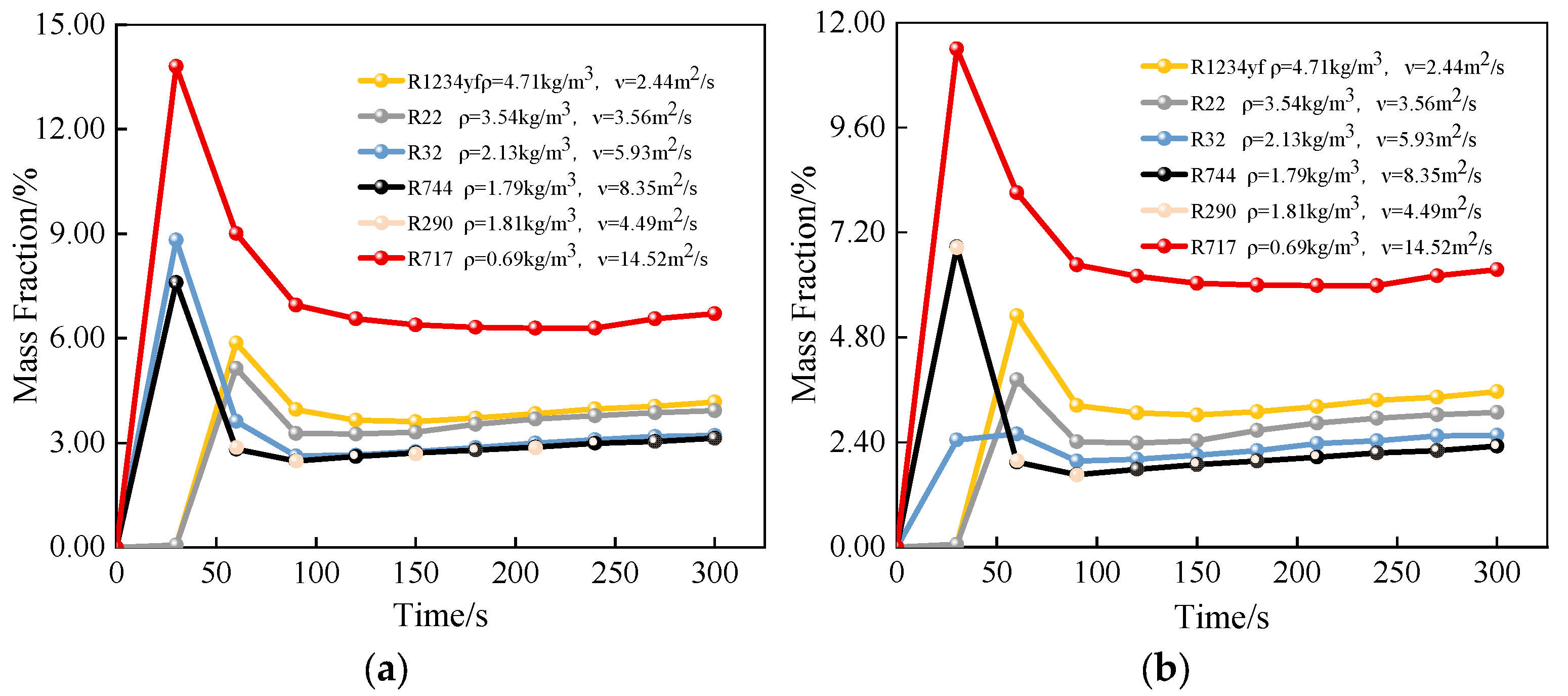
3.1. Diffusion Characteristics of the Refrigerant During Vertical Upward Leakage

Figure 5 and Figure 6 depict the concentration distributions of various refrigerants in the xy and zy planes within the confined space for a leakage duration of 300 s. It can be seen from Figure 5 and Figure 6 that following a vertical upward leakage, all the refrigerants initially accumulated above the leakage source. Subsequently, driven by the initial momentum of the jet and density differences and viscous forces between the refrigerant and air, the refrigerant impacts the top and diffuses along the top and sidewalls towards regions of lower concentration. However, the diffusion and concentration distribution exhibit significant variations among the different refrigerants due to their distinct thermophysical properties. It can be seen from Figure 5a,b and Figure 6a,b that for the denser refrigerants like R1234yf and R22, the initial leakage velocity is lower due to the same mass flow rate. Upon impact with the top, these refrigerants tend to move along the top away from the leakage source, with their horizontal velocity rapidly diminishing. This weakens the influence of the initial momentum on the diffusion process. Under the action of gravity (refrigerant density is greater than air), the diffusion direction of the refrigerant is significantly deflected. Consequently, the refrigerant diffuses toward the floor and accumulates in the area above the floor, creating a pronounced vertical concentration gradient. The high-concentration areas are primarily localized above the floor and directly above the leakage point. Conversely, for lower-density refrigerants such as R32 and R290, the initial momentum dominates the diffusion process, while the effects of gravity and viscosity are less pronounced. After impacting the top, these refrigerants diffuse extensively along the top and sidewalls. The high-concentration areas are more localized and concentrated around the leakage source, in the lower corners, and above the floor. Compared to R1234yf and R22, R32 and R290 exhibit a more even spatial distribution and a less pronounced vertical concentration gradient. It can be seen from Figure 5f and Figure 6f that for R717, which has a significantly lower density than the other refrigerants, buoyancy forces dominate. The refrigerant, being lighter than air, tends to accumulate in the upper region of the confined space after leakage. This results in a high concentration in the upper region and a lower concentration near the floor. It can be seen from Figure 5d,e and Figure 6d,e that for R290 and R744, which have similar densities, the diffusion process and concentration distribution exhibit close similarities. During the leakage process, the diffusion of the refrigerant is primarily influenced by the initial momentum and gravity (buoyancy), with a relatively minor influence from viscosity.
A comparative analysis of the refrigerant concentrations at the 0.5 m and 0.7 m positions above the leakage source was conducted. Figure 7 gives the temporal evolution of these concentrations, revealing a common trend: an initial rapid increase, followed by a gradual decrease, and finally stabilization. Under the same leakage mass flow rates and leakage hole diameters, the refrigerant density significantly influences its behavior. A low-density refrigerant, such as R717, exhibits higher leakage velocities and greater diffusion areas. Buoyancy forces drive these refrigerants towards the upper region, resulting in higher concentrations above the leakage hole. Conversely, high-density refrigerants like R1234yf and R22 display slower leakage velocities and weaker turbulent diffusion due to interactions with the top. This leads to greater accumulation near the leakage hole and the floor, consequently increasing the local concentrations. Intermediate-density refrigerants (R32, R290, R744), while denser than air, exhibit stronger turbulent diffusion due to the initial momentum. This results in a more even distribution within the room, leading to lower concentrations above the leakage hole. Steady-state concentration values at 0.5 m were as follows: R717 (6.51%) > R1234yf (3.87%) > R22 (3.57%) > R32 (2.92%) > R290 (2.83%) > R744 (2.81%). At 0.7 m, the order was as follows: R717 (6.15%) > R1234yf (3.25%) > R22 (2.72%) > R32 (2.01%) > R290 (1.99%).

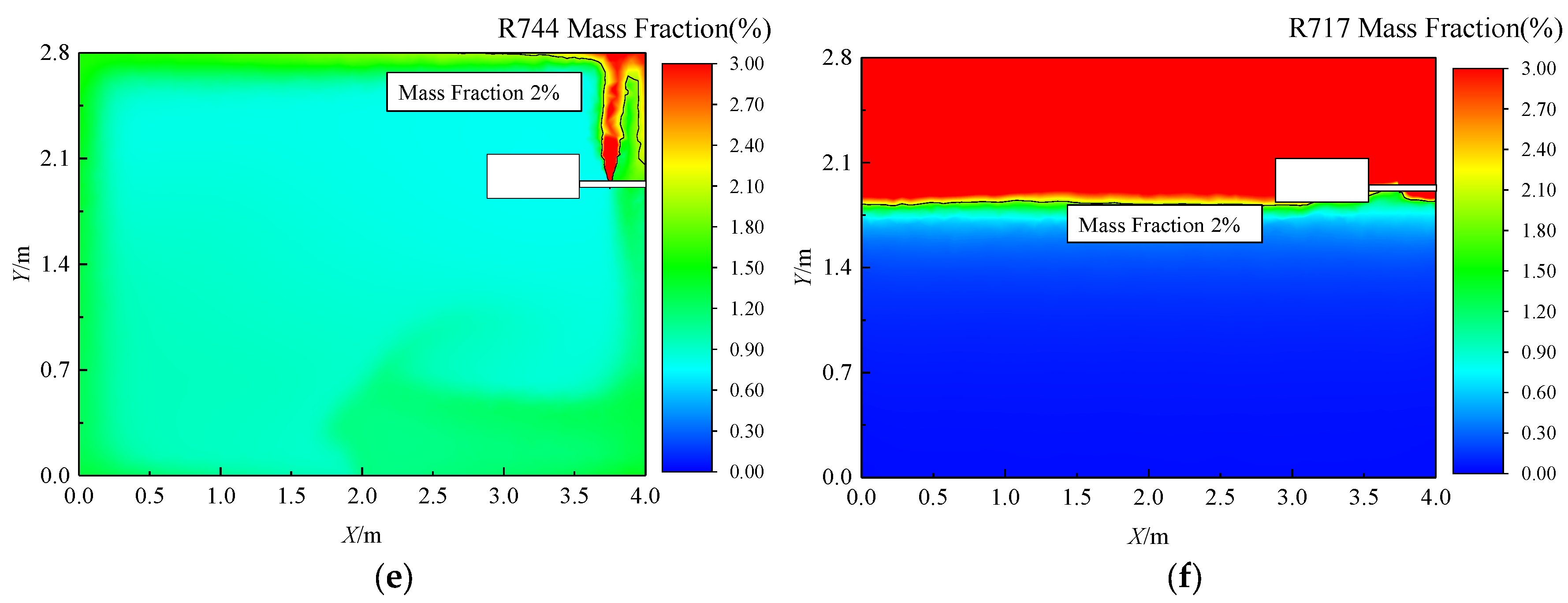
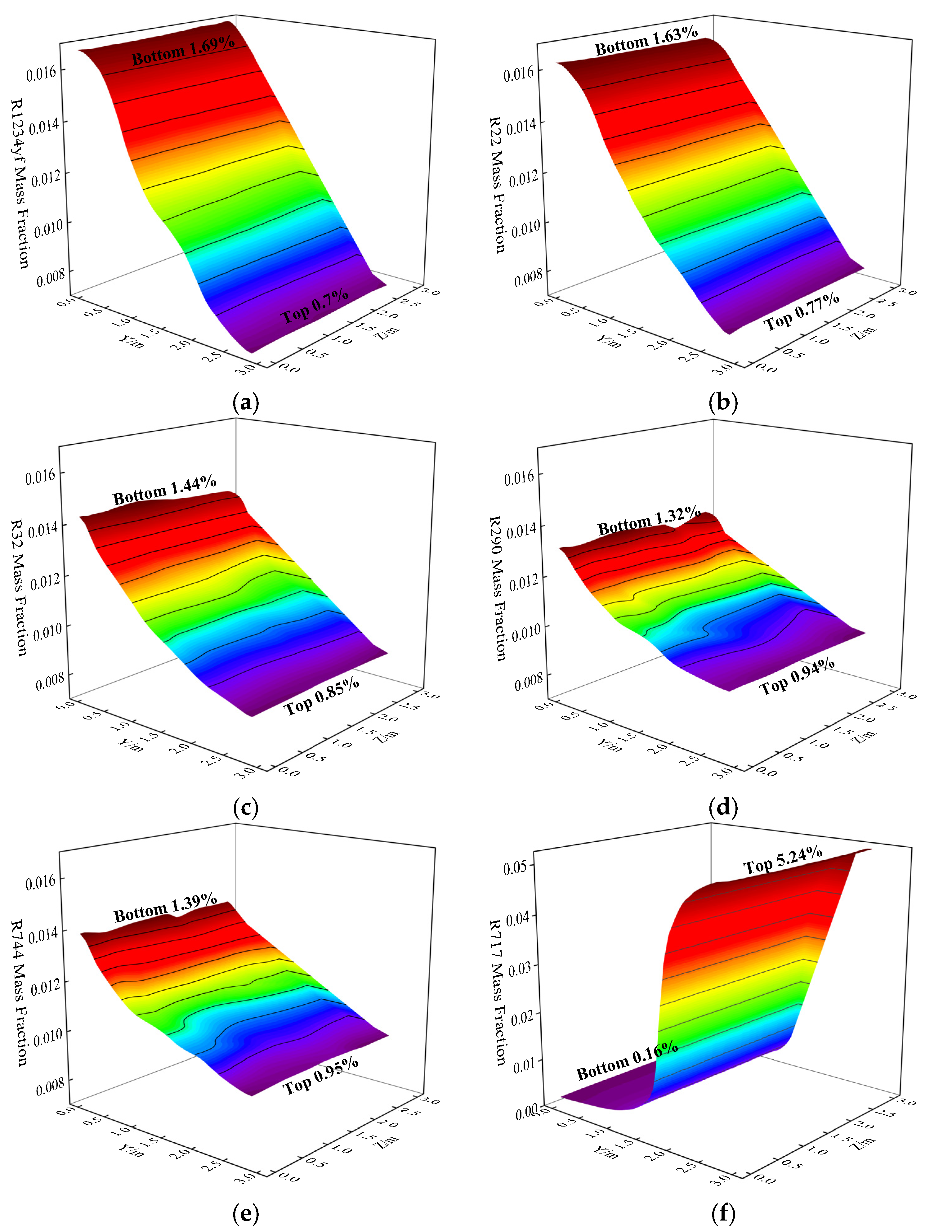
3.2. Deposition Characteristics of Refrigeration in a Confined Space After the Leak Ends

Figure 8 illustrates the concentration distribution of different refrigerants on the yz (x = 2 m) plane 30 min after free diffusion following a leakage event. It can be seen from Figure 8 that after the leak stops, free diffusion of the refrigerants results in significant variations in their spatial distribution, with distinct deposition characteristics observed at the bottom of the space. Refrigerants with high densities, such as R1234yf, exhibit higher concentrations near the floor (1.69%) and lower concentrations at the top of the room (0.7%). For refrigerants with lower densities, this trend reverses: R22 (1.63% bottom, 0.77% top), R32 (1.44% bottom, 0.85% top), and R290 (1.32% bottom, 0.94% top). This behavior is attributed to the initial downward diffusion of denser-than-air refrigerants, leading to accumulation near the floor. Subsequently, the gravity, viscosity, and concentration gradients drive a downward flow towards the upper region. Due to their slower diffusion rates, the denser refrigerants exhibit a more pronounced deposition near the floor. Conversely, R717, being less dense than air, accumulates at the top of the room (5.24%) with significantly lower concentrations near the floor (0.16%). Furthermore, a comparison of R290 and R744, which have similar densities, highlights the influence of viscosity. R744, with its higher viscosity, exhibits a greater concentration at the bottom of the room (1.39%) compared to R290. This suggests that a higher viscosity can impede refrigerant diffusion, leading to increased deposition. These results underscore the significant impact of both density and viscosity on the distribution and deposition characteristics of different refrigerants following a leakage.

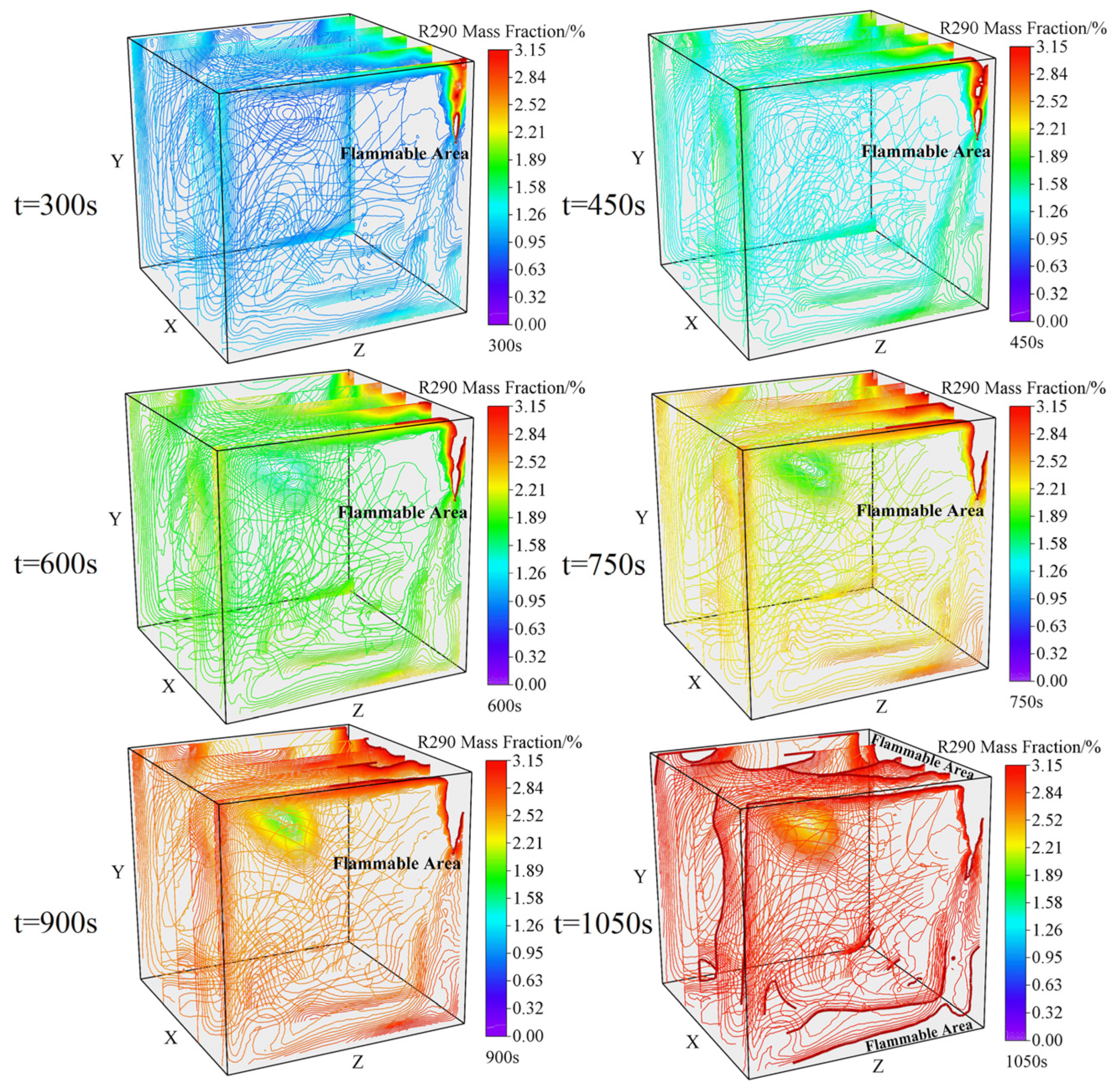
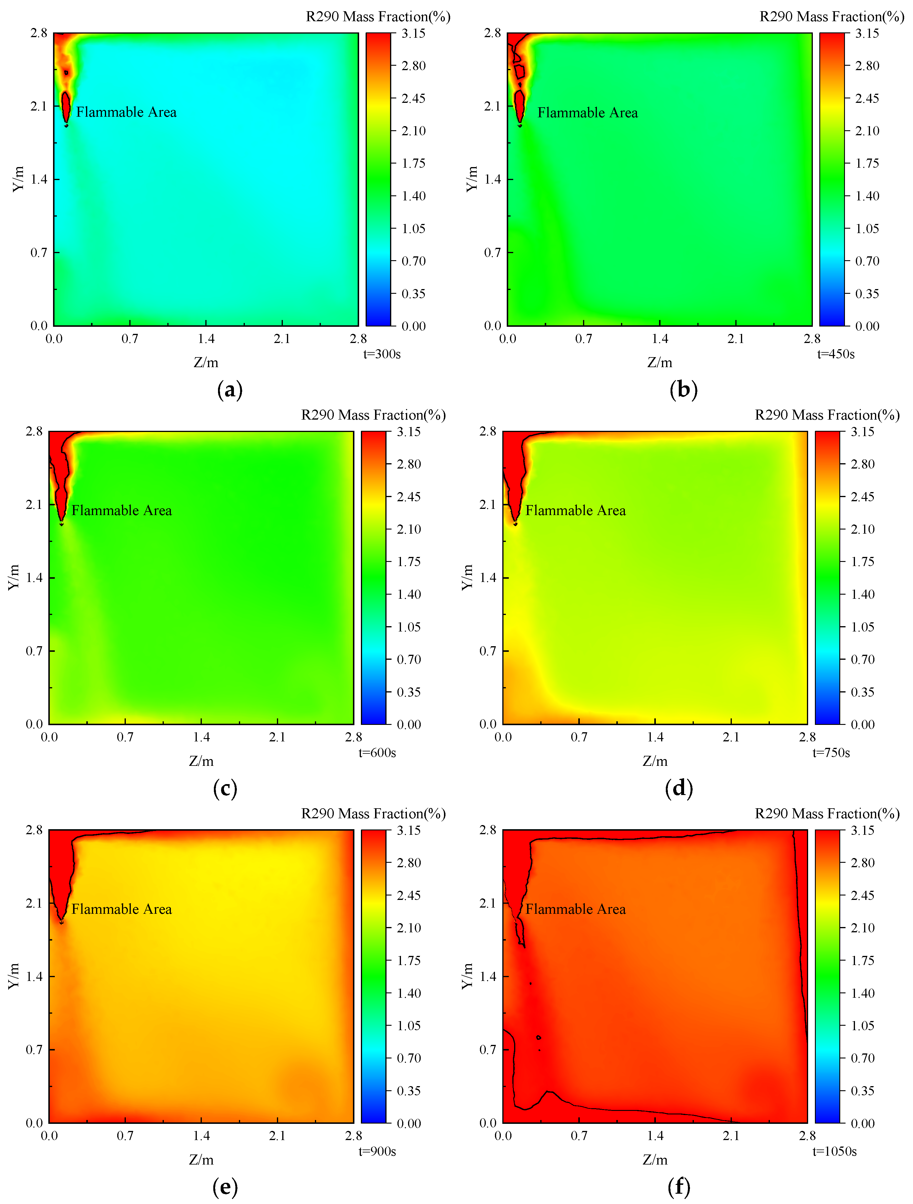
3.3. Research on the Explosion Area When Refrigerant Leaks Vertically Upwards

Through the above analysis, it was found that after the refrigerant leaks vertically upward in a confined space, it will accumulate above the leakage hole and in a local area near the floor, and the refrigerant concentration is relatively high. However, when the amount of refrigerant leakage is small, the concentration of the refrigerant in the confined space is still below its lower flammability limit, and no flammability area is formed in the space. As the leakage time increases, the amount of refrigerant leakage increases, and a flammability area may be formed in the space.
Using R290 as an example, this work analyzes the migration characteristics and the boundary variations of the flammability area resulting from different amounts of vertical upward leakage. Figure 9 shows the changes in the flammability area within the confined space during the vertical leakage of R290. The analysis considers leakage durations ranging from 300 s to 1050 s and refrigerant leakage amounts between 360 g and 1260 g. It can be seen from Figure 6 that when the leakage duration is 300 s, the flammability area of R290 is initially confined to a region approximately 0.3 m above the leakage source. As the amount of refrigerant leakage increases, the flammability area expands vertically towards the top. By 450 s, the vertical boundary of the explosion area reaches the top. With a further increase in the leakage duration to 600 s, refrigerant accumulates in the corner of the wall directly above the leakage hole, leading to the formation of an explosion area in that region. However, the spatial extent of the flammability area remains relatively limited. As the leakage continues and the amount of refrigerant increases, the flammability area begins to extend horizontally along the top away from the leakage hole. At 900 s, the flammability area’s horizontal boundary (X-direction) extends to 3.5 m from the leakage hole, while its vertical boundary (Z-direction) reaches 1.3 m from the leakage hole. Finally, at a leakage duration of 1050 s with a leakage amount of 1260 g, significant refrigerant accumulation occurs at the bottom of the room. This results in the formation of a large-scale flammability area layer encompassing the top, walls, and floor.
Figure 10 shows the variation in the combustible area of R290 with vertical upward leakage in a limited space at different leakage times (300–1050 s). It can be seen that when the leakage time is 300 s, only Y = 0.6 m in front of the leakage hole exists in the explosion region; when the leakage time is 450 s, the explosion area has spread to the top of the room; when the leakage time is 600 s, the explosion area reaches about Y = 0.9 m in front of the leakage hole and begins to spread around the top of the room. When the leakage time is 750 s, the explosion area is further expanded, and the explosion area at the top of the room spreads to Z = 0.7 m; when the leakage time is 900 s, the explosion area at the top of the room has spread to Z = 1.05 m, a certain degree of accumulation occurs at the top of the room, and a small range of refrigerant accumulation and deposition occurs near the wall. When the leakage time was 1050 s, the explosion area covered the entire top of the room and spread down along the wall, and the refrigerant deposited near the wall formed a new explosion area.

4. Conclusions

The diffusion and deposition characteristics of different refrigerants (including R717, R290, R32, and R1234yf) was investigated by simulating vertical upward leakage within a confined space, and the migration characteristics of flammability areas in space under different leakage amounts were further discussed. The conclusions were drawn as follows:
(1)
Upon vertical upward leakage within a confined space, the refrigerant initially contacts the top. It subsequently diffuses laterally along the top surface away from the leakage point. Refrigerants with higher densities tend to migrate downwards towards the floor, while those with lower densities exhibit a greater tendency to diffuse along the top and side walls of the combined space.
(2)
After the leakage stops, refrigerants with higher density such as R1234yf mainly diffuse laterally along the top surface, away from the leakage source. Denser refrigerants exhibit a greater tendency to settle towards the floor, whereas less dense refrigerants primarily diffuse along the top and side walls. R744, with its higher density and viscosity, demonstrates a higher concentration near the floor compared to R290. For refrigerants with lower densities, the concentration near the floor diminishes, while the concentration at the top increases, resulting in a less pronounced deposition effect.
(3)
The leakage amount and leakage duration have a significant impact on the formation and expansion of the flammability area. Considering the vertical upward leakage of R290 within a confined space as an example, increasing the leakage amount or prolonging the leakage duration results in a gradual expansion of the flammability area. This expansion encompasses a wider area, extending towards the top, walls, and floor of the combined space. Actually, at 300 s, the explosion region is at Y = 0.6 m. By 450 s, it reaches the ceiling. At 600 s, the area extends to Y = 0.9 m and spreads across the ceiling. By 750 s, the ceiling area spreads to Z = 0.7 m. At 900 s, it reaches Z = 1.05 m, with accumulation at the top and deposition near the wall. At 1050 s, the explosion area covers the entire ceiling and spreads down the wall, forming a new area near the wall due to refrigerant deposition.
In summary, the diffusion and deposition characteristics of various refrigerants during vertical upward leakage within a confined space were analyzed in this work. This research provides crucial insights for assessing the explosion risk associated with the leakage of flammable refrigerants.

Author Contributions

Methodology, Y.L. (Yalun Li); Software, Y.L. (Yongjie Lu); Formal analysis, N.J.; Investigation, X.Z.; Resources, Y.L. (Yongjun Ling); Writing—review & editing, P.Z.; Supervision, X.H. All authors have read and agreed to the published version of the manuscript.

Funding

This research was funded by National Natural Science Foundation of China (Grant No. 51936007 and No. 52076185).

Institutional Review Board Statement

Not applicable.

Informed Consent Statement

Not applicable.

Data Availability Statement

Data is contained within the article.

Acknowledgments

This work is supported by the National Natural Science Foundation of China (Grant No. 51936007 and No. 52076185).

Conflicts of Interest

Author Yongjun Ling was employed by the company Zhejiang Zhongguang Electrical Co., Ltd. The remaining authors declare that the research was conducted in the absence of any commercial or financial relationships that could be construed as a potential conflict of interest.

Nomenclature

tleakage time, s
ppressure, Pa
Ttemperature, K
cpconstant pressure heat capacity, J/(kg·K)
ktturbulent thermal conductivity, W/(m·K)
Dtturbulent mass diffusion coefficient, m2/s
gacceleration of gravity, m/s2
uvelocity of refrigerant, m/s
ffriction coefficient of the pipeline wall
Greek symbols
ρdensity, kg/m3
μviscosity, kg/(m·s)
ωmass fraction
Subscripts
aair
rrefrigerant
mmixture
i, junit vector direction
tturbulent
ppressure
Acronyms
GWPglobal warming potential
HFCshydrofluorocarbons

References

  1. Air Conditioners Market Global Forecast Report by Countries Covered in Commercial Air Conditioners Market (PAC, VRF) Room Air Conditioners Market (Window-Type, Split-Type) Types (Split Type (Single), Split Type (Multi), PAC, VRF, Others) Countries and Company Analysis, 2024–2032. Available online: https://www.renub.com/global-air-conditioner-market-p.php (accessed on 18 January 2025).
  2. Li, Y.; Yang, J.; Wu, X.; Liu, Y.; Zhuang, Y.; Zhou, P.; Han, X.; Chen, G. Leakage, Diffusion and Distribution Characteristics of Refrigerant in a Limited Space:A Comprehensive Review. Therm. Sci. Eng. Prog. 2023, 40, 101731. [Google Scholar] [CrossRef]
  3. Francis, C.; Maidment, G.; Davies, G. An Investigation of Refrigerant Leakage in Commercial Refrigeration. Int. J. Refrig. 2017, 74, 12–21. [Google Scholar] [CrossRef]
  4. Beshr, M.; Aute, V.; Sharma, V.; Abdelaziz, O.; Fricke, B.; Radermacher, R. A Comparative Study on the Environmental Impact of Supermarket Refrigeration Systems Using Low GWP Refrigerants. Int. J. Refrig. 2015, 56, 154–164. [Google Scholar] [CrossRef]
  5. U.N. Environment Programme. The Kigali Amendment to the Montreal Protocol: HFC Phase-Down|Ozonaction. Available online: https://www.unep.org/ozonaction/resources/factsheet/kigali-amendment-montreal-protocol-hfc-phase-down (accessed on 27 January 2025).
  6. The Kigali Amendment to the Montreal Protocol on Substances that Deplete the Ozone Layer_Ministry of Ecology and Environment of the People’s Republic of China. Available online: https://www.mee.gov.cn/ywgz/dqhjbh/xhcycwzhjgl/202106/t20210621_841063.shtml (accessed on 22 December 2024).
  7. F-Gases: New Rules on Labelling, Reporting, Certification and the F-Gas Portal—European Commission. Available online: https://climate.ec.europa.eu/news-your-voice/news/f-gases-new-rules-labelling-reporting-certification-and-f-gas-portal-2024-09-20_en (accessed on 22 December 2024).
  8. Yadav, S.; Liu, J.; Kim, S.C. A Comprehensive Study on 21st-Century Refrigerants—R290 and R1234yf: A Review. Int. J. Heat Mass Transf. 2022, 182, 121947. [Google Scholar] [CrossRef]
  9. Ibrahim, O.A.A.-M.; Kadhim, S.A.; Hammoodi, K.A.; Rashid, F.L.; Askar, A.H. Review of Hydrocarbon Refrigerants as Drop-in Alternatives to High-GWP Refrigerants in VCR Systems: The Case of R290. Clean. Eng. Technol. 2024, 23, 100825. [Google Scholar] [CrossRef]
  10. Zhao, S.; Li, X.; Wang, L.; Chang, M. State-space model development and dynamic performance simulation of solar-powered single-effect Libr-H2O absorption chiller. Renew. Energy 2025, 241, 122327. [Google Scholar] [CrossRef]
  11. Deng, N.; Sun, H.; Wang, H. Application of Hydrocarbon Refrigerant R600a/R290 in Refrigerator. Refrig. Air-Cond. 2022, 22, 37–41. [Google Scholar] [CrossRef]
  12. Niu, H.; Liu, X.; Wang, B.; Shi, W. Development, Research and Policy Status of Logistics Cold Storage in the Context of Carbon Neutrality: An Overview. Energy Build. 2024, 320, 114606. [Google Scholar] [CrossRef]
  13. Wang, L.; He, Y.; Ren, J.; Wang, D.; Dai, B.; Zhang, Z. Simulation of Diffusion of Combustible Refrigerants R1234yf and R290 Leakage in Automotive Air Conditioning. Int. J. Refrig. 2024, 168, 326–333. [Google Scholar] [CrossRef]
  14. Zhang, S.; Liu, R. Research on performance of R290 household air conditioner. Home Appl. Technol. 2024, 22–27. [Google Scholar] [CrossRef]
  15. Fang, Y.; Wu, M.; Guo, Z.; Ni, H.; Han, X.; Chen, G. Evaluation on Cycle Performance of R161 as a Drop-in Replacement for R407C in Small-Scale Air Conditioning Systems. J. Therm. Sci. 2022, 31, 2068–2076. [Google Scholar] [CrossRef]
  16. Zhang, S.; Yang, Z.; He, H.; Zhao, Y.; Hao, S.; Hou, Z.; Shu, Y. The Impact of Refrigerant Leakage on the Dynamic Operating Performance of R600a Refrigerator Systems. Appl. Therm. Eng. 2024, 257, 124228. [Google Scholar] [CrossRef]
  17. Ning, Q.; He, G.; Fan, M.; Xiong, J.; Li, X. Flammable Refrigerant Leakage Hazards Control for Split-Type Household Air Conditioners. Int. J. Refrig. 2022, 144, 188–201. [Google Scholar] [CrossRef]
  18. Zhang, W.; Yang, Z.; Li, J.; Ren, C.; Lv, D.; Wang, J.; Zhang, X.; Wu, W. Research on the Flammability Hazards of an Air Conditioner Using Refrigerant R-290. Int. J. Refrig. 2013, 36, 1483–1494. [Google Scholar] [CrossRef]
  19. Li, Y.; Zhou, P.; Zhuang, Y.; Wu, X.; Liu, Y.; Han, X.; Chen, G. An Improved Gas Leakage Model and Research on the Leakage Field Strength Characteristics of R290 in Limited Space. Appl. Sci. 2022, 12, 5657. [Google Scholar] [CrossRef]
  20. Li, Y.; Zhou, P.; Ye, G.; Yan, Y.; Ouyang, H.; Han, X. Diffusion and Distribution Characteristics of Refrigerants under Horizontal Leakage in a Confined Space. Refrig. Air-Cond. 2025, 64, 1–11. [Google Scholar]
  21. Li, Y.; Yang, J.; Wu, X.; Liu, Y.; Zhou, P.; Yan, Y.; Han, X. Research on the Field Strength Characteristics and the Flammable Area of Refrigerants Leakage into a Confined Space. Int. J. Refrig. 2023, 153, 308–322. [Google Scholar] [CrossRef]
  22. Maojuan, H.; Jinbo, L.; Zhe, L.; Tingxun, L. Experimental and Numerical Simulation Analysis of R-290 Air Conditioner Leak. Int. J. Refrig. 2018, 90, 163–173. [Google Scholar] [CrossRef]
  23. Elatar, A.; Abu-Heiba, A.; Patel, V.; Edwards, K.D.; Baxter, V.; Abdelaziz, O.; Zhang, M. Evaluation of Flammable Volume in the Case of a Catastrophic Leak of R-32 from a Rooftop Unit. Int. J. Refrig. 2018, 91, 39–45. [Google Scholar] [CrossRef]
  24. Colbourne, D.; Šuen, K. R290 Concentrations Arising from Leaks in Commercial Refrigeration Cabinets. In Proceedings of the 12th IIR Gustav Lorentzen Conference on Natural Refrigerants (GL2016), Édimbourg, UK, 21–24 August 2016. [Google Scholar] [CrossRef]
  25. Liu, Q.; Zhang, H.; Liu, Y.; Huang, H.; Zhang, X.; Li, Z.; Yao, W. Influencing Factors of Flammable Refrigerants Leaking in Building Air- Conditioning System. Procedia Eng. 2013, 62, 648–654. [Google Scholar] [CrossRef]
  26. Ram Prakash, C.; Gautham, M.; Mohan Lal, D.; Devotta, S.; Colbourne, D. CFD Simulation of HC-290 Leakage from a Split Type Room Air Conditioner. Proc. Inst. Mech. Eng. Part E J. Process Mech. Eng. 2021, 235, 1847–1857. [Google Scholar] [CrossRef]
  27. Papas, P.; Zhang, S.; Jiang, H.; Verma, P.; Rydkin, I.; Lord, R.; Burns, L. Computational Fluid Dynamics Modeling of Flammable Refrigerant Leaks inside Machine Rooms: Evaluation of Ventilation Mitigation Requirements. Sci. Technol. Built Environ. 2016, 22, 463–471. [Google Scholar] [CrossRef]
  28. Tang, W.; He, G.; Zhou, S.; Sun, W.; Cai, D.; Liu, F. The Experimental Study of R290 Mass Distribution and Indoor Leakage of 2 HP and 3 HP Split Type Household Air Conditioner. Int. J. Refrig. 2019, 100, 246–254. [Google Scholar] [CrossRef]
  29. Ning, Q.; He, G.; Sun, W.; Fan, M.; Li, X.; Hong, Z. R290 Leakage Hazards Assessment of a 1 HP Split-Type Household Air Conditioner by Concentration Detection and Ignition Experiment. Int. J. Refrig. 2022, 139, 70–83. [Google Scholar] [CrossRef]
  30. Zhang, W.; Yang, Z.; Wang, J.; Lv, D.; Zhong, Z. Leakage Research of Split-type Air-conditioner using R290 as Refrigerant. J. Refrig. 2013, 34, 42–47. [Google Scholar] [CrossRef]
  31. Patel, V.K.; Abuheiba, A.; Chambers, J.; Elatar, A.; Jajja, S.; Baxter, V.; Reshniak, V. Experimental Evaluation of Refrigerant Leak Characteristics for Different HVAC&R Equipment Types–Phase 2; Oak Ridge National Laboratory (ORNL): Oak Ridge, TN, USA, 2019. Available online: https://info.ornl.gov/sites/publications/Files/Pub119328.pdf (accessed on 27 January 2025).
  32. Oreilly, H.; Kohoutek, T.; Crombie, D. An Experimental and Numerical Study of Refrigerant Leaks in Refrigerated Transport Containers. Available online: https://iifiir.org/en/fridoc/an-experimental-and-numerical-study-of-refrigerant-leaks-in-34288 (accessed on 27 January 2025).
  33. Jin, W.; Jia, L.; Zhang, Y. Effect of Air Supply Velocity and Angle on R32 Leakage and Diffusion. Huagong Xuebao/CIESC J. 2015, 66, 2351–2358. [Google Scholar] [CrossRef]
  34. Zhang, Y.; Liu, C.; Wang, T.; Pan, L.; Li, W.; Shi, J.; Chen, J. Leakage Analysis and Concentration Distribution of Flammable Refrigerant R290 in the Automobile Air Conditioner System. Int. J. Refrig. 2020, 110, 286–294. [Google Scholar] [CrossRef]
Figure 1. Schematic diagram of the gas leakage process in the improved model (Arrows represent refrigerant gas movement) [19].
Applsci 15 01918 g001
Figure 3. Grid independence verification.
Applsci 15 01918 g003
Figure 4. The comparison between simulation and experimental results (mass flow rate = 0.0018 kg/s).
Applsci 15 01918 g004
Figure 5. Concentration contours of different refrigerants at Z = 0.115 m.(a) R1234yf, (b) R22, (c) R32, (d) R290, (e) R744, (f) R717. (t = 300 s).
Applsci 15 01918 g005aApplsci 15 01918 g005b
Figure 6. Concentration contours of different refrigerants at x = 3.75 m. (a) R1234yf, (b) R22, (c) R32, (d) R290, (e) R744, (f) R717. (t = 300 s).
Applsci 15 01918 g006
Figure 7. The refrigerant concentration at (a) 0.5 m and (b) 0.7 m above the leakage space varies with time.
Applsci 15 01918 g007
Figure 8. Cloud map of concentration distribution for various refrigerants at the yz plane (x = 2 m) within the confined space. (a) R1234yf, (b) R22, (c) R32, (d) R290, (e) R744, (f) R717.
Applsci 15 01918 g008
Figure 9. The characteristics of the flammability area for R290 leakage in a confined space with different leakage durations (300–1050 s) and corresponding leakage amounts (360–1260 g).
Applsci 15 01918 g009
Figure 10. The variation in flammable area in the case of vertical upward leakage of R290 in a limited space at different leakage times (300–1050 s). (a) t = 300 s, (b) t = 450 s, (c) t = 600 s, (d) t = 750 s, (e) t = 900 s, (f) t = 1050 s. (Y-Z plane at X = 3.75 m).
Applsci 15 01918 g010
Table 1. Physical property parameters of the refrigerant selected in this paper at room temperature (25 °C) and atmospheric pressure (0.1 MPa).
RefrigerantTemperature
(K)
Pressure (MPa)Density (kg/m3)Specific Heat
kJ/(kg·K)
Heat Conductivity
mW/(m·K)
Viscosity
μPa·s
R717298.150.10130.692.1625.1610.08
R290298.150.10131.811.6818.298.12
R32298.150.10132.130.8512.5112.61
R1234yf298.150.10134.710.9013.8311.46
R22298.150.10133.540.6610.5712.62
R744298.150.10131.790.8516.6214.91
Note: All physical properties were checked by Refprop 10.0 software.
Table 2. Mass flow of different refrigerants at room temperature when leakage aperture is 3 mm.
RefrigerantR717R290R1234yfR22R32R744
Leakage rate/(g/s)1.3082.0183.1912.9022.3942.001
Disclaimer/Publisher’s Note: The statements, opinions and data contained in all publications are solely those of the individual author(s) and contributor(s) and not of MDPI and/or the editor(s). MDPI and/or the editor(s) disclaim responsibility for any injury to people or property resulting from any ideas, methods, instructions or products referred to in the content.

