1. Introduction
In recent years, the integration of renewable energy photovoltaic power generation has seen rapid growth [
1,
2,
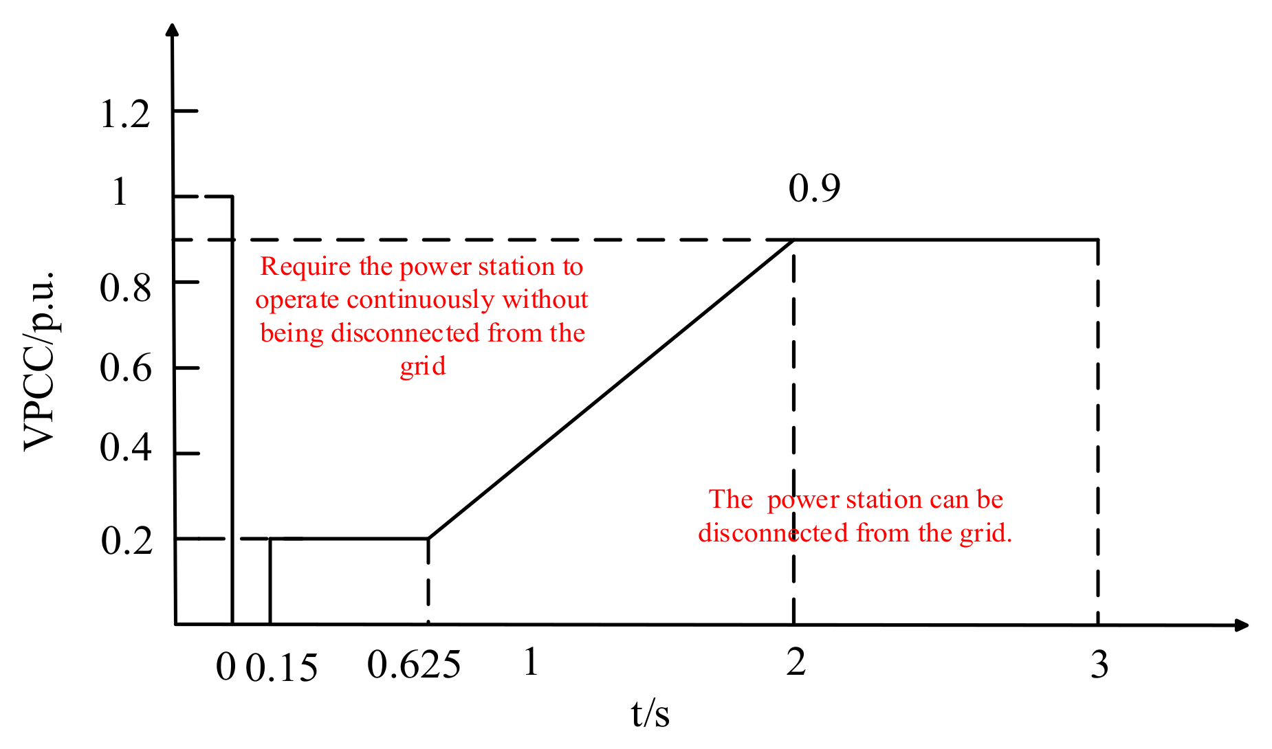
3]. Nevertheless, faults or disturbances in the power grid can cause the voltage at the PCC of photovoltaic stations to decline. Grid-connected systems must possess a certain degree of LVRT capability.
Figure 1 illustrates that, when the voltage dip falls within the range indicated above the dashed line, the photovoltaic system continues to operate without disconnecting from the grid, supplying reactive current to stabilize the PCC voltage.
Owing to its precise replication of synchronous generator inertia and damping, the VSG has emerged as the leading control approach for grid-tied inverters. The concept of a virtual synchronous generator, which entails incorporating the inertia and damping characteristics of a synchronous generator into the control strategy of grid-connected inverters, was first introduced in literature [
4]. Subsequently, literature [
5,
6] crafted the droop control equation for the VSG by mirroring the primary frequency and voltage control mechanisms of synchronous generators, thereby decoupling the active and reactive power loops. However, no intervention was made on the virtual synchronism and power angle, leading to issues with power angle stability. Literature [
7] bolstered the power angle stability of the VSG system through the application of the virtual power angle increment technique. In literature [
8], the VSG control methodology was integrated into the LVRT strategy for renewable energy systems, successfully enabling LVRT via a dual-mode switching control mechanism for inverters. Lastly, in literature [
9], by establishing a VSG model for permanent magnet direct-drive wind turbines, a new power compensation setpoint during LVRT scenarios was introduced. It was pointed out that when the grid voltage dip is not severe, active power can be maintained constant while an appropriate amount of reactive power is increased, thereby enhancing resource utilization beyond the original setpoint.
The aforementioned research on VSG control strategies and their LVRT capabilities assumes a three-phase symmetrical voltage sag scenario in the power grid. Yet, in real-world operations, unbalanced load power and various faults in distribution networks often lead to unbalanced and harmonically disturbed grid voltage sags during power system short-circuit faults, challenging the maintenance of balanced and stable grid-connected currents in VSG systems. To tackle this, literature [
10] introduces a technique that integrates virtual impedance with phasor current limiting for direct voltage-controlled VSG systems, efficiently constraining both transient and steady-state fault currents. However, this approach assumes a single fault in the grid and neglects complex faults characterized by harmonic-laden unbalanced voltage sags. Literature [
11] employs a DSOGI to extract positive and negative sequence components of the grid voltage, achieving balanced grid-connected currents by suppressing the negative sequence component of the grid-connected current. This control strategy performs well under low harmonic grid voltage conditions, but its efficacy in acquiring grid frequency and phase using a traditional DSOGI-PLL diminishes when the grid voltage contains significant harmonics.
This paper investigates the LVRT control strategy for VSG under harmonic-containing asymmetric voltage sags in the power grid. The objective is to improve traditional control strategies to stabilize grid-connected currents when the grid voltage contains harmonic interference or a certain degree of imbalance. Firstly, an LC-type VSG control model is established to analyze the impact of grid voltage, particularly under unbalanced sags, on the grid-connected currents during the LVRT of the VSG. Secondly, the traditional DSOGI-PLL is improved to achieve good filtering performance in grids with rich harmonics. Then, a feedforward function is analyzed and constructed, and grid voltage feedforward control is introduced to mitigate the impact of grid voltage imbalance on grid-connected currents. Finally, PSCAD simulations are conducted to verify the effectiveness and authenticity of the proposed control strategy in this paper.
2. Basic Principles of VSG and Low-Voltage Ride-Through Requirements
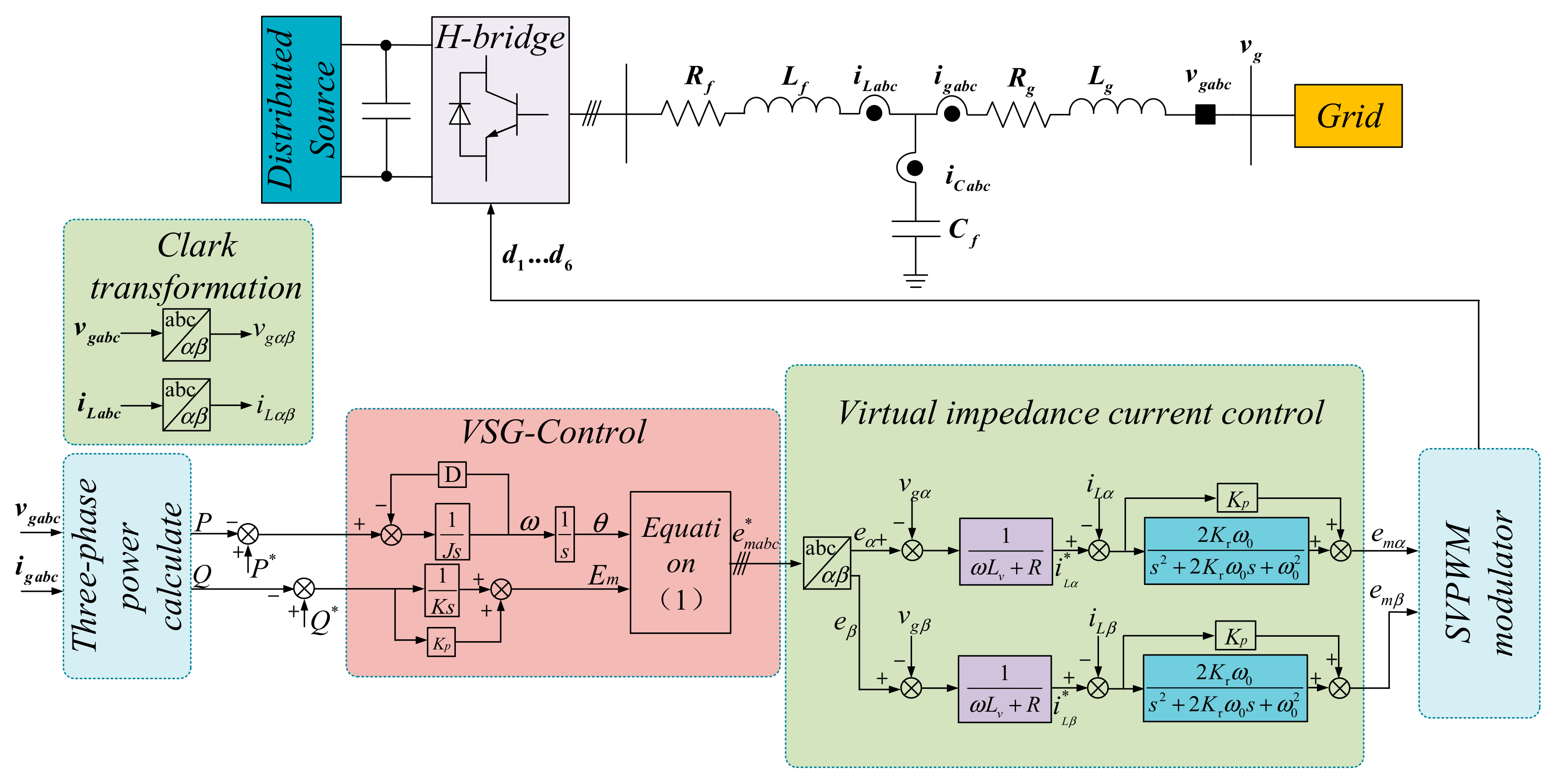
The typical VSG model, as shown in
Figure 2, simulates the inertia and damping of a synchronous generator through control methods. In this model:
eabc denotes the voltage at the midpoint of the inverter’s leg,
ilabc is the inverter output current,
igabc is the grid-connected current.
Rf,
Lf, and
Cf constitute the impedance of the LC filter circuit.
vgabc represents the voltage at the PCC.
Lg and
Rg are the grid-side impedances. D is the active damping coefficient.
J is the virtual inertia.
ω is the virtual angular frequency.
Em is the voltage magnitude of the VSG.
emabc* is the three-phase voltage generated by the VSG model.
Lv =
Lf +
Lg and
R =
Rf +
Rg represent the virtual impedance.
iLαβ* is the reference value of the inverter output current.
Em is the modulation wave.
d1–
d6 are the modulation signals.
Equation (1) in the figure is as follows:
In accordance with national grid interconnection standards, the reactive current iqref injected into the grid by the inverter must meet the specified condition when the grid voltage magnitude decreases from
Vgn to
Vpcc.
where
IN is the rated current output by the VSG.
Utilizing the instantaneous power formula while neglecting switching device and filter circuit losses, the grid-side voltage vector
vg aligns precisely with the d-axis component of the grid-side voltage, denoted as
vgd. As a result, during the LVRT period, the reference values for the active and reactive power outputs of the VSG can be calculated using the following equations [
12,
13,
14]:
In the equation, vgd and vgq represent the d-axis and q-axis components of the voltage at the PCC, respectively, where .
The specific flowchart for the low-voltage ride-through based on VSG is shown in
Figure 3:
When the system detects a grid voltage sag signal, it disconnects the outer voltage loop and instead calculates the power reference values based on the reactive current. After the grid voltage recovers, the outer voltage loop is switched back on to provide the reference value for active power, completing the low-voltage ride-through process [
15,
16].
3. Improvement of DSOGI-PLL
When the grid voltage harmonic content is minimal, the DSOGI-PLL effectively utilizes its inherent filtering capabilities to precisely extract the positive-sequence phase and frequency signals of the grid voltage. However, in scenarios with high grid harmonic content, the extraction accuracy of positive-sequence voltage-related signals may be compromised. In this section, we propose an enhancement to the traditional DSOGI-PLL by incorporating an Advanced Harmonic Elimination (AHE) module prior to the extraction of positive and negative sequences. This enhancement involves cascading multiple AHEs to eliminate harmonics of various orders, thereby enabling accurate extraction of positive-sequence-related signals even when the grid voltage contains substantial asymmetric harmonics [
17,
18,
19].
3.1. DSOGI-PLL
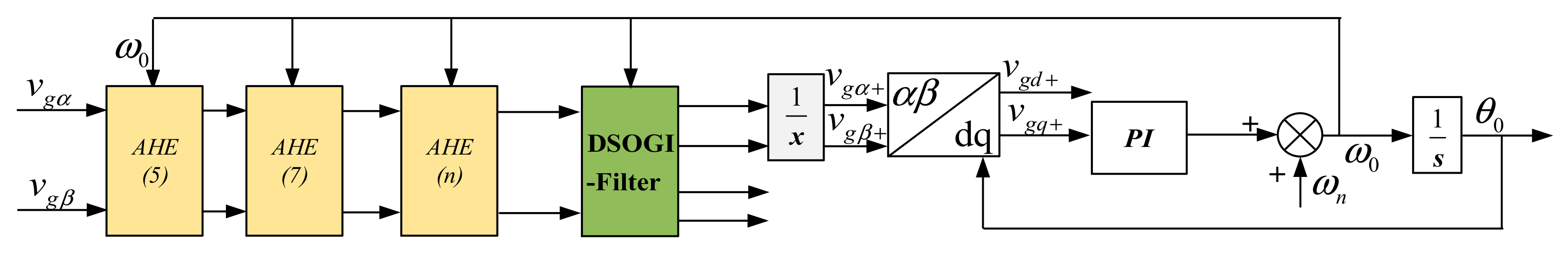
The approach utilizing the DSOGI boasts minimal delay and superior dynamic performance, enabling the acquisition of grid voltage phase under conditions of asymmetric grid voltage. The structural schematic diagram for this method is illustrated in
Figure 4 below [
20].
In the diagram, vgα and vgβ represent the grid voltage in a two-phase stationary reference frame; vgα+ and vgα− represent its positive-sequence and negative-sequence components, respectively; vgd+ and vgq+ represent the grid voltage in a two-phase rotating reference frame; ωn is the rated angular frequency of the grid; and θ0 is the phase angle of the positive-sequence grid voltage.
The DSOGI-PLL is essentially a combination of the DSOGI filter and the SRF-PLL. The fundamental design principle of the DSOGI filter is illustrated in
Figure 5.
In the Figure, q represents a 90° lag, and vαf, vβf are the grid voltages on the alpha-beta axes after being filtered by the SOGI. In practical modulation, a value of 0.707 is taken, and vi, vo represent the input voltage and output voltage of the SOGI, respectively.
The transfer function of the SOGI is given by the following equation:
The magnitude-frequency response of its transfer function is given by the following equation:
It is clear that, when the input angular frequency is zero, the output signal will track the input signal accurately without any steady-state error, while the amplitudes of all other harmonic signals will be attenuated. As a result, the SOGI inherently functions as a filter.
3.2. Drawbacks of DSOGI-PLL Under Complex Faults
The asymmetrical grid voltage vabc can be decomposed into its positive-sequence, negative-sequence, and zero-sequence components. The formulae for the positive-sequence and negative-sequence components are given below [
21].
where:
After the grid voltage undergoes the Clark transformation, the positive and negative sequence components are expressed as follows after passing through the DSOGI-Filter:
Based on the previous analysis, it is clear that to separate the positive and negative sequence components of the grid voltage, one must initially obtain the grid voltage components in the two-phase stationary coordinate system. However, when the grid voltage contains significant harmonics, the filtering capability of the SOGI alone is insufficient. A comprehensive analysis is presented below.
The three-phase voltage during complex asymmetric faults with harmonics can be expressed as:
In the equation: ki = 0, +1, −1; V+, V−, and Vn represent the amplitudes of the positive-sequence, negative-sequence, and nth harmonic components of the grid voltage, respectively; +, −, and n represent the initial phase angles of the positive-sequence, negative-sequence, and nth harmonic components of the grid voltage, respectively; and ω0 is the fundamental frequency of the grid voltage.
Equation (10), transformed into the two-phase stationary coordinate system, is expressed as:
where:
;
.
Taking this as the input signal of the SOGI, and combining Equations (9) and (11), the output signal of the SOGI can be obtained as:
In the equation: vαon* and vβon* represent the output values of the nth harmonic after passing through the SOGI.
After performing positive and negative sequence calculations using Equation (9) on Equation (12), the fundamental positive-sequence component of the grid voltage is obtained as:
Equation (13) reveals that the derived fundamental positive-sequence component includes an nth harmonic component. To mitigate the impact of harmonics, the nth harmonic should be eliminated prior to decomposing and computing the positive and negative sequence components of the voltage.
3.3. Improved DSOGI-PLL Based on AHE
After comparing Equations (12) and (13), it is found that multiplying
vαo by the coefficient 1/
n and then adding it to
qvβo can eliminate the nth harmonic of the voltage component on the
α-axis. Similarly, multiplying
vβo by the coefficient 1/
n and then subtracting it from
qvαo can eliminate the nth harmonic of the voltage component on the
β-axis. The newly obtained two-phase stationary voltages can be expressed as:
In the equation, vαβ+− represents the two-phase stationary coordinate system voltage without the nth harmonic component.
Equation (14) indicates that the transformed two-phase voltages no longer contain the nth harmonic component, despite changes in the amplitudes of the positive and negative sequence components. In the presence of other harmonics in the power grid, their amplitudes will also change, but their harmonic orders will remain unchanged. Multiple AHE modules can be used to remove individual harmonics separately. After that, the obtained positive and negative sequence components are corrected to obtain a positive sequence component that is free of harmonics. The structure of the AHE module is illustrated in
Figure 6.
By setting the number of AHE modules and the value of n, the harmonics in the grid can be eliminated in sequence. For example, to target the main harmonics in the power grid, which are the 5th, 7th, and 11th harmonics, it is sufficient to set
n to 11 in
Figure 7. The DSOGI-PLL structure based on cascaded AHE modules is shown in
Figure 7:
Each application of the harmonic pre-elimination module not only removes the nth harmonic but also modifies the amplitudes of the positive and negative sequence voltages. Consequently, it becomes essential to adjust the output of the DSOGI-PLL to precisely acquire the fundamental voltage components in the two-phase stationary coordinate system. The value of
x in the diagram can be calculated using the equation provided below:
For example, when dealing with the main harmonics in the power grid, which are the 5th, 7th, and 11th harmonics, the correction coefficient x is calculated as follows: x = (1/5 − 1) × (1/7 − 1) × (1/11 − 1) = −48/77.
5. Simulation Verification
In this section, simulations were conducted in PSCAD. The main simulation parameters are shown in
Table 1 below. The data were sourced from the Electrical Engineering Laboratory at North China University of Water Resources and Electric Power.
(1) Simulation Comparison of Improved DSOGI-PLL
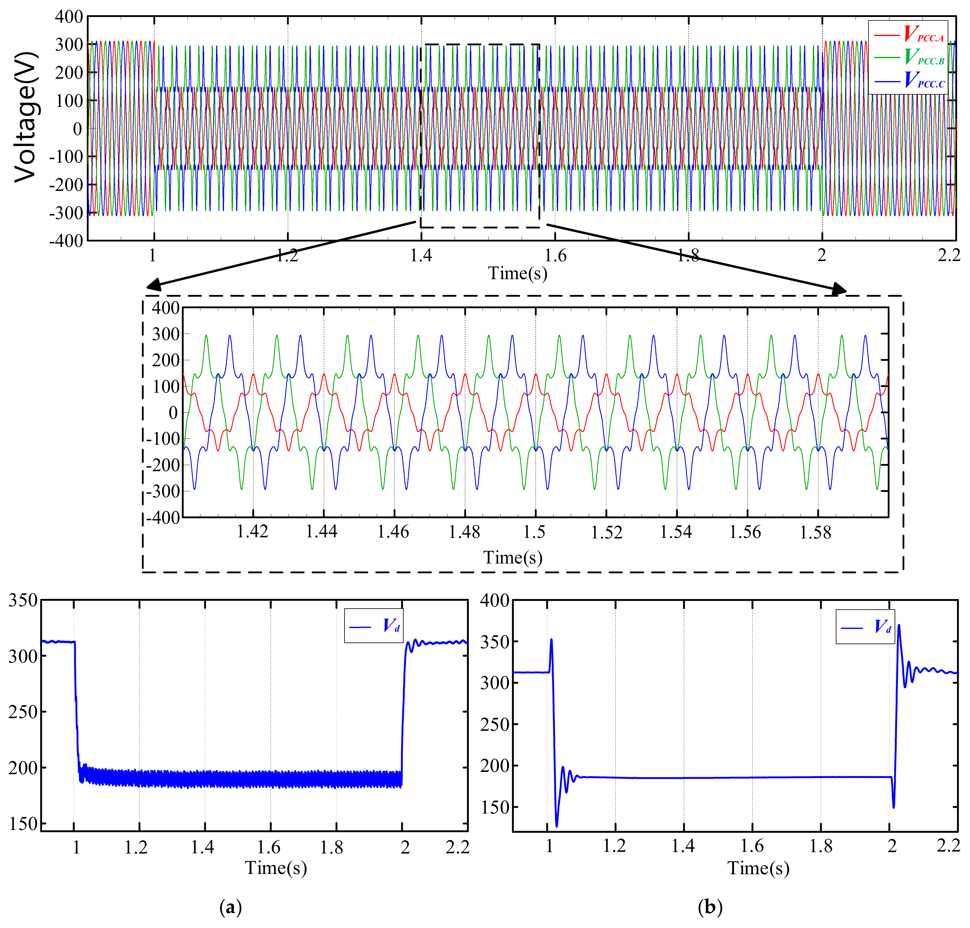
The simulation configuration is as follows: Between 1 s and 2 s, an asymmetric voltage sag containing harmonics occurs in the three-phase grid voltage. Specifically, the BC-phase voltage decreases to 70% of the nominal voltage, whereas the A-phase voltage drops to 50% of the BC-phase voltage. Furthermore, each of the three-phase voltages includes a 20% component of the 5th harmonic, a 10% component of the 7th harmonic, and a 5% component of the 11th harmonic.
Figure 11 contrasts the frequency response of the conventional DSOGI-PLL with the enhanced AHE-DSOGI-PLL, which incorporates harmonic pre-elimination. Both PLLs achieve 0 dB gain at 50 Hz and maintain a phase margin. However, in the high-frequency range, the improved DSOGI-PLL outperforms the traditional version in suppressing harmonics. As a result, the conventional DSOGI-PLL struggles to accurately leading to issues with the VSG’s low-voltage ride-through control system.
Figure 12a shows the d-axis voltage waveform using the traditional DSOGI-PLL, and
Figure 12b shows the positive-sequence d-axis voltage waveform using the improved DSOGI-PLL. It can be observed that the positive-sequence d-axis voltage under the traditional DSOGI-PLL experiences fluctuations within 15 V due to harmonic interference. In contrast, the improved DSOGI-PLL, which incorporates a harmonic elimination module in advance, exhibits a stable positive-sequence d-axis voltage during the fault, stabilizing at 184.5 V with negligible fluctuation amplitude.
Figure 13 compares the frequencies obtained by two different PLLs. It can be observed that the grid voltage frequency obtained by the traditional DSOGI-PLL, under asymmetric fault conditions with harmonic distortion in the grid voltage, experiences fluctuations of 0.6 Hz, which fails to meet the frequency detection standards. In contrast, the improved DSOGI-PLL can quickly and accurately obtain the grid voltage frequency, with a deviation of only 0.005 Hz from the power frequency of 50 Hz.
In conclusion, the enhanced DSOGI-PLL effectively extracts the positive and negative sequence components as well as the frequency of the grid voltage during asymmetric faults with abundant harmonics. Its precise frequency detection also allows for accurate phase determination. Conversely, the conventional DSOGI-PLL fails to perform similarly under intricate grid fault conditions.
(2) Simulation of VSG Low-Voltage Ride-Through Under Complex Grid Faults
The simulation settings for the VSG LVRT control strategies are identical to those used for PLL simulations.
Figure 14a depicts the grid-connected current when using the traditional VSG LVRT control strategy paired with an enhanced PLL, while retaining the standard grid voltage feedforward control.
Figure 14b showcases the grid-connected current when employing the traditional dsogi-pll alongside the grid voltage feedforward control method.
Figure 14c displays the grid-connected current when using the AHE-DSOGI-PLL proposed in this study, combined with the grid voltage feedforward control method. Notably, the grid-connected current in
Figure 14a exhibits significant asymmetry and high distortion, attributed to the absence of the proposed grid voltage feedforward control strategy, which allows grid voltage harmonics to disrupt the current. The grid-connected current in
Figure 14b sees an improvement in asymmetry due to the application of the grid voltage feedforward control presented in this paper, which eliminates the impact of grid voltage imbalance. However, the traditional DSOGI-PLL’s inability to accurately obtain the positive-sequence grid voltage results in high distortion of the grid-connected current. In contrast,
Figure 14c demonstrates that during LVRT, the grid-connected current remains balanced with minimal harmonics and a stable amplitude of 40 A, highlighting the effectiveness of the proposed control strategy.
In
Figure 14a, despite the adoption of an improved PLL, the traditional VSG LVRT control strategy still causes the grid-connected current to be strongly influenced by asymmetry in the grid voltage, resulting in distorted and asymmetric current waveforms. In
Figure 14b, although the imbalance of the grid-connected current is improved, the grid-connected current experiences significant distortion due to the shortcomings of the traditional DSOGI-PLL. On the other hand,
Figure 14c demonstrates the performance of the VSG LVRT control strategy when both the improved PLL and the proposed grid voltage feedforward control are implemented simultaneously. The resulting grid-connected current is notably balanced, with a substantial reduction in harmonic content, and its amplitude remains constant at 40 A throughout the LVRT process. This comparison emphasizes the importance of adopting the proposed grid voltage feedforward control strategy in achieving a stable and harmonic-free grid-connected current.
Figure 15 presents a comparison of active and reactive power under different control strategies, In the diagram,
P represents active power and
Q represents reactive power. From
Figure 15a, it can be observed that, without the implementation of grid voltage feedforward control, both active and reactive power experience significant fluctuations, hindering the ability of the VSG control system to achieve LVRT capability.
Figure 15b demonstrates that, when grid voltage feedforward control is used but the AHE-DSOGI-PLL is not employed, the fluctuations in active and reactive power are reduced to some extent, yet they still cannot provide stable active and reactive power to the grid. However, as shown in
Figure 15c, when the improved control strategy proposed in this paper is applied, active and reactive power exhibit abrupt changes only during grid voltage variations. This approach enables the system to supply reactive power to the grid during complex fault scenarios. Specifically, during the LVRT period, active power remains stable at 10 kW, while reactive power stabilizes at 2483 Var, ensuring the successful achievement of LVRT for the VSG system.
Figure 16 presents the distortion rate of the A-phase current during the LVRT period, obtained through Fourier analysis.
Figure 16a depicts the distortion rate image of the compensated A−phase current under traditional control, with a fundamental current content of 61.3 A and a Total Harmonic Distortion (THD) of 63.7%, which is significantly higher than the grid connection standard of 5%.
Figure 16b displays the distortion rate image of the A−phase current after applying grid voltage feedforward control but without using the AHE−DSOGI-PLL. The fundamental current content is 39.4 A, and the THD is 14.7%, still exceeding the grid connection current distortion standard.
Figure 16c shows the grid connection current distortion rate image when the improved control strategy proposed in this paper is adopted. The fundamental current content is 39.4 A, and the THD is 3.72%, meeting the grid connection standard.
In summary, the control strategy introduced in this paper improves the VSG system’s resistance to interference. During asymmetric faults with harmonics in the grid voltage, it ensures a balanced grid-connected current, enabling the system to produce steady active and reactive power to support the grid voltage. This successfully enables the VSG system to achieve LVRT under harmonic grid voltage interference.


