1. Introduction
Titanium and its alloys have been utilized in biomedical applications since the mid-20th century, with early research focusing on pure titanium and Ti-6Al-4V alloy [
1,
2,
3,
4,
5]. While these materials offered excellent mechanical strength, concerns regarding the potential cytotoxicity of vanadium and aluminum prompted the development of more biocompatible alternatives, such as Ti-13Zr-13Nb [
6]. This alloy was specifically engineered to enhance biological compatibility while retaining the advantageous properties of titanium-based materials [
6,
7,
8]. The Ti-13Zr-13Nb alloy, a second-generation titanium alloy, addresses limitations of first-generation alloys in biomedical applications. Its low elastic modulus closely matches that of human bone, reducing stress-shielding effects and promoting bone healing and integration [
9]. Additionally, its high biocompatibility and corrosion resistance make it suitable for long-term implant applications [
6,
7,
8,
9,
10]. However, the alloy’s inherent bioactivity remains suboptimal [
11].
The development of antibacterial coatings on titanium and its alloys represents a critical research area in biomedical engineering, addressing a fundamental limitation of these materials: their bio-inertness, which prevents them from combating bacterial infections that lead to severe clinical complications. Despite their excellent mechanical properties and biocompatibility, titanium-based orthopedic or dental implants lack inherent antibacterial capabilities, leaving them vulnerable to bacterial colonization, biofilm formation, and peri-implant infections. These complications represent a leading cause of implant failure, generating significant social and economic costs. The study by Ferraris and Spriano [
12] examines surface modification strategies for titanium implants to combat bacterial infections. The authors analyze passive approaches (e.g., nanostructures that hinder bacterial adhesion) and active methods (e.g., coatings incorporating silver or copper nanoparticles, antibiotics). They emphasize the need to balance antibacterial efficacy with biocompatibility, highlighting risks such as cytotoxicity due to excessive metal ion release. Promising future directions include “smart responsive coatings” (e.g., stimuli-triggered antibiotic release) and biofilm-disrupting nanomaterials.
Contemporary strategies in biomaterial engineering focus on developing multifunctional coatings that combine bioactivity and antibacterial properties. For instance, Qin et al. [
13] designed a one-step method to fabricate hydroxyapatite (HA)-containing coatings on titanium alloys using micro-arc oxidation (MAO) with calcium gluconate and calcium glycerophosphate as calcium and phosphorus sources. This approach enabled the direct formation of an HA layer during MAO, resulting in a coating with excellent adhesion, biocompatibility, and potential for orthopedic implants. The simplified process reduces production costs and enhances scalability. Meanwhile, Zhao et al. [
14] developed a dual-functional Mg-doped TiO
2 coating on titanium. Magnesium ions promote osteogenesis by stimulating osteoblast differentiation, while TiO
2 exhibits antibacterial activity under light via reactive oxygen species (ROS) generation, effectively inhibiting pathogens such as
Staphylococcus aureus. This synergy between bone regeneration and infection control offers a promising solution for dental and orthopedic implants. Both studies highlight the trend toward next-generation implants that minimize complications while actively supporting tissue healing and integration.
To enhance the Ti-13Zr-13Nb alloy’s biocompatibility, mechanical properties, and regenerative potential, various surface modification methods have been proposed [
6,
7,
8,
9,
10,
11,
12,
13,
14,
15,
16,
17,
18], including: (i) severe plastic deformation via high-pressure torsion to create ultrafine-grained surfaces with improved mechanical strength [
10]; (ii) plasma electrolytic oxidation (PEO) to generate porous oxide structures for enhanced osseointegration and calcium ion incorporation [
16]; (iii) hybrid laser–micro-arc oxidation for composite surfaces with superior wear resistance and bioactivity [
17]; (iv) electrophoretic deposition (EPD) to produce chitosan (CS) coatings co-deposited with silver nanoparticles (AgNPs) with antimicrobial properties from AgNPs and improved biocompatibility via chitosan [
18]; and (v) anodizing to form porous oxide layers that improve biocompatibility, cell adhesion, and corrosion resistance [
7,
8,
11,
19,
20,
21,
22,
23,
24]. Porous oxide layers, in particular, enhance the alloy’s performance as a drug delivery platform [
11].
CS exhibits excellent biocompatibility, non-toxicity, and biodegradability, making it suitable for surface coatings on implantable medical devices (e.g., titanium implants) [
25]. Its degradation products are harmless to the human body, and its degradation rate can be tuned to align with tissue repair processes. CS serves as a sustained-release carrier for drugs (e.g., antibiotics) and growth factors, enabling localized controlled-release systems that prolong therapeutic efficacy while minimizing systemic side effects. In bone repair, CS binds metal ions (e.g., calcium, magnesium) to improve osseointegration [
25,
26]. The cationic nature of CS disrupts bacterial cell membranes, inhibits pathogenic bacteria, and modulates inflammatory cytokine expression to reduce tissue inflammation [
27]. The core advantages of CS coatings lie in their multifunctionality (drug delivery, antimicrobial action, pro-regenerative effects) and biosafety [
28,
29].
Recent advances in surface engineering have shown that electrophoretic deposition (EPD) is a versatile and cost-effective technique for producing uniform, adherent chitosan-based coatings with tunable thickness and porosity. EPD allows precise control of deposition parameters and is compatible with bioactive molecule incorporation. Several studies have demonstrated the successful EPD fabrication of CS coatings on titanium, cobalt-chromium-molybdenum alloy, magnesium alloys, and stainless steel 316 L substrates [
30,
31,
32,
33,
34,
35], often to improve corrosion resistance, bioactivity, antibacterial behavior or drug delivery. These coatings are often applied to improve corrosion resistance, bioactivity, antibacterial behavior, or drug delivery. However, reports on EPD-deposited drug-loaded chitosan coatings on Ti-13Zr-13Nb alloys remain scarce. Moreover, the integration of such coatings with anodically formed, fluoride-containing porous oxide layers has not been previously described.
Therefore, this study aims to develop and characterize chitosan–tetracycline (CS–TC) composite coatings deposited by EPD and dip-coating (DC) onto anodized Ti-13Zr-13Nb substrates. Tetracycline (TC) was selected due to its broad-spectrum antibacterial activity against Gram-positive and Gram-negative bacteria and its anti-inflammatory properties [
36,
37]. The novelty of this work lies in the combination of a fluoride-assisted anodizing process with CS–TC coatings, providing a multifunctional surface with controlled drug release, tunable mechanical properties, and antibacterial potential. To tailor drug release profiles for diverse clinical needs, CS-TC-oxide layer hybrid coatings were obtained via dip coating (DC) and EPD methods. This research establishes a foundation for the design of next-generation Ti-13Zr-13Nb implants with enhanced bioactivity and therapeutic performance.
2. Materials and Methods
2.1. Substrate Preparation
The substrate used for surface modification was a Ti-13Zr-13Nb biomedical alloy (wt.%) (BIMO TECH, Wrocław, Poland) supplied as a 30 mm diameter wire. Discs of 5 mm thickness were cut from the wire and subsequently divided into four equal quadrants. The ASTM F1713-08(2021)e1 standard specifies that Ti-13Zr-13Nb alloy bars and wires must meet stringent requirements for chemical composition, mechanical properties, and metallurgical characteristics, ensuring suitability for surgical implants requiring durability, biocompatibility, and performance [
38]. Surface finish requirements outlined in the standard were achieved via mechanical grinding using a Metkon Forcipol 102 metallographic grinding-and-polishing machine (Metkon Instruments Inc., Bursa, Turkey) at 250 rpm. Sequential polishing was performed with SiC abrasive papers (Struers Inc., Cleveland, OH, USA) of 600, 1200, 3000, and 5000 grits.
2.2. Cleaning Procedure
The ground Ti-13Zr-13Nb samples underwent a three-stage cleaning process in a USC 300 TH ultrasonic cleaner (VWR International, Radnor, PA, USA) to remove residues. First, they were immersed in acetone and subjected to 15 min of ultrasonic cleaning. This was followed by immersion in ethanol (both solvents supplied by Avantor Performance Materials Poland S.A., Gliwice, Poland) with an additional 15 min ultrasonic treatment to remove residual organic contaminants. Finally, the samples were immersed in ultrapure water (18.2 MΩ cm resistivity), produced using a Milli-Q® Advantage A10 Water Purification System (Millipore SAS, Molsheim, France), and ultrasonically cleaned for 15 min to eliminate any residual cleaning agents.
2.3. Anodizing Conditions
The Ti-13Zr-13Nb electrodes were prepared by attaching an insulated copper wire to the back surface using chemically resistant silver epoxy (Elecrodag 915, TAAB Laboratories Equipment Ltd., Aldermaston, UK). To ensure insulation, the back and side surfaces were then encapsulated with a two-component epoxy adhesive (Distal Classic, Libella Ltd., Warsaw, Poland).
The electrodes were ultrasonically cleaned prior to anodizing in a custom electrolyte containing 1 M ethylene glycol (EG, anhydrous, 99.8%; Sigma-Aldrich, Saint Louis, MO, USA) with 4 wt.% sodium fluoride (NaF, 99.99% trace metals basis; Sigma-Aldrich, Saint Louis, MO, USA). This formulation was designed to promote the growth of porous oxide layers on the Ti-13Zr-13Nb alloy surface. One-step anodizing was performed at room temperature using a PWR800H high-current power supply (Kikusui Electronics Corp., Yokohama, Japan) in a two-electrode configuration. Cathode (C) was a Pt–Ir mesh (8 cm2 geometric surface area). Anode (A) was a Ti-13Zr-13Nb sample (1.77 cm2 geometric surface area) positioned 2 cm parallel to C. A constant voltage of 20 V was applied for 120 min. Post-anodizing, each A underwent a 5 min immersion in vigorously stirred ultrapure water.
2.4. CS-TC Co-Deposition
2.4.1. Dip Coating Method (DC)
CS-TC coatings were deposited onto anodized Ti-13Zr-13Nb substrate via DC method. A 2% (
v/
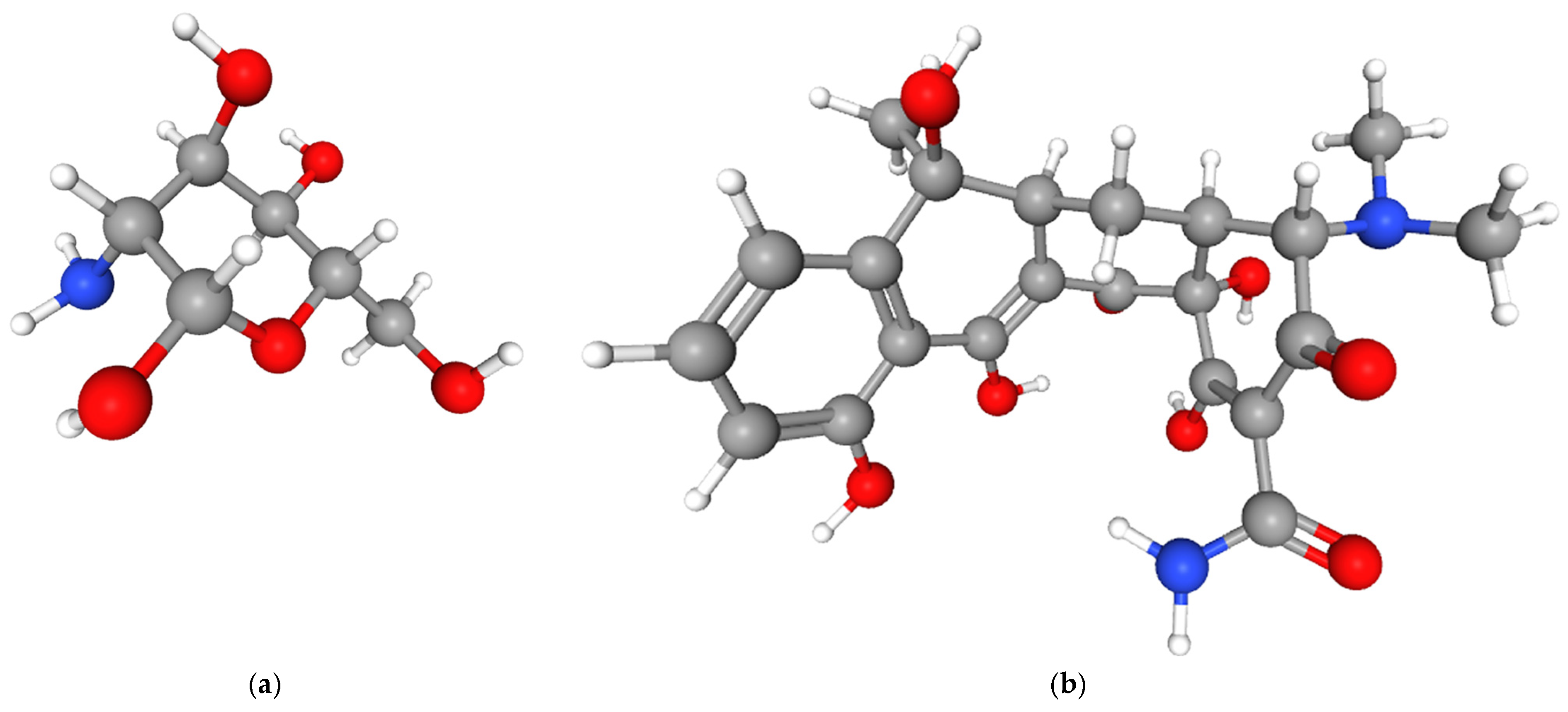
v) acetic acid solution containing 2 g of CS (Sigma-Aldrich, Saint Louis, MO, USA; MW: 80 kDa, deacetylation degree: 75–85%) served as the coating precursor. The CS biopolymer, derived from chitin deacetylation, consist of β-(1→4)-linked D-glucosamine units (C
6H
13NO
5) (
Figure 1a) [
39]. Its polymeric structure is represented as (C
6H
11NO
4)
n, where “n” denotes the degree of polymerization. The molecular formula difference between the monomer (C
6H
13NO
5) and polymer (C
6H
11NO
4) arises from the elimination of two hydrogen atoms and one oxygen atom during chitin’s deacetylation to CS.
Tetracycline (TC, Sigma-Aldrich, Saint Louis, MO, USA), with the molecular formula C
22H
24N
2O
8 features a characteristic hydronaphthacene structure comprising four fused rings (A–D) (
Figure 1b) [
39]. Key functional groups governing its antibacterial activity [
40] and stability include: ketone (C1) and amino (C2) groups on ring A; dimethylamino group at C4; hydroxyl groups at C6 (acid/alkaline stability), C10 (phenolic), and C12; methyl group at C7 (mediates ribosomal interactions); conjugated C11 ketone-C10 phenolic system (photodegradation sensitivity). The TC structure exhibits pH-, light-, and oxidation-dependent instability [
41].
In CS-TC coating procedure, TC (1 mg) was dissolved in 1 mL of 2% (w/v) CS solution. 50 mL CS solution was mixed with 50 mL TC solution to obtain 100 mL CS-TC precursor. Anodized Ti-13Zr-13Nb substrates were immersed in 25 mL CS-TC solution (1 min, room temperature), withdrawn at 2 mm s−1 for uniform wetting, drained (30 s), and air-dried at room temperature. Single-layer (DC1) and triple-layer (DC3) CS-TC coatings were fabricated via sequential dip cycles.
2.4.2. Electrophoretic Deposition Method (EPD)
CS-TC coatings were deposited onto anodized Ti-13Zr-13Nb substrates via EPD method. A precursor solution was prepared by dissolving 2 g of CS in 2% (w/v) acetic acid, followed by addition of TC at 1 mg mL−1. The EPD cell configuration consisted of working electrode (C) as anodized Ti-13Zr-13Nb substrate and counter electrode (A) as platinum mesh (parallel configuration, 2 cm separation). A direct current power supply applied 30 V for 10 min, inducing migration of charged CS/TC particles toward the cathode. This resulted in uniform CS-TC coating deposition at room temperature. Single-layer (EPD1) and triple-layer (EPD3) CS-TC coatings were fabricated by repeating the deposition cycle with intermediate drying steps.
2.5. Scanning Electron Microscopy Study
Microstructural analysis of Ti-13Zr-13Nb substrates before and after surface modification was performed using a TESCAN Mira 3 LMU scanning electron microscope (SEM, TESCAN ORSAY HOLDING, Brno-Kohoutovice, Czech Republic) equipped with a Schottky field-emission electron gun for high-resolution imaging and an Oxford Instruments energy dispersive spectroscopy system (EDS, Abingdon, UK) for elemental mapping. Samples were sputter-coated with 5 nm chromium layer using a Quorum Q150T ES sputter coater (Quorum Technologies, East Sussex, UK) to enhance conductivity and minimize charging effects. Secondary electron imaging was conducted at 10 kV accelerating voltage with a working distance of 5 mm. EDS spectra were acquired at 15 kV with a 60 s acquisition time to ensure statistically significant elemental quantification. The analysis was also conducted using a JEOL JSM-6480 SEM (JEOL, Tokyo, Japan) with the EDS method at an operating voltage of 20 kV (IXRF, Austin, TX, USA). The elemental composition values presented in
Table 1 represent the mean ± standard deviation of five EDS measurements taken from different areas of the anodized surface. Due to the semi-quantitative nature of EDS analysis, data normality testing was not performed.
2.6. Optical Microscopy Study
The surface morphology of CS-TC coatings deposited on anodized Ti-13Zr-13Nb substrates (via DC and EPD methods) was characterized using a Delta Optical Biolight 300 microscope (Teleskopy, Warsaw, Poland). Optical microscopy analysis assessed uniformity, roughness, TC particle distribution/agglomeration, thickness and surface defects (cracks, pinholes). Images were acquired at 40× magnification (NA = 0.65) across five distinct 1 mm2 regions per sample to ensure representative sampling.
2.7. Porosity Study
The porosity of CS-TC coatings was quantified via digital image analysis using optical microscopy images and the ImageJ software (v1.53k) with the JPOR macro [
42]. This automated workflow applied adaptive thresholding to distinguish pores (pixel intensity < threshold) from the coating matrix (intensity > threshold). The JPOR macro enabled batch processing of 10 images per sample (40× magnification, 1.2 MP resolution), ensuring statistically robust measurements with <2% inter-image variability. Compared to manual methods, this approach improved reproducibility by standardizing threshold selection and eliminating operator bias.
2.8. Thickness Study
The thickness of porous oxide layers on Ti-13Zr-13Nb substrates was measured non-destructively using a Novotest TP-2020 coating thickness gauge (Blum-Novotest GmbH, Grünkraut, Germany) employing the amplitude-sensitive eddy current method. The NF-2 probe, optimized for anodized non-ferrous metals, provided measurements in the 0–60 µm range [
43]. Ten measurements per sample were collected across a 1 cm × 1 cm grid pattern, with mean thickness and standard deviation calculated to assess layer uniformity. The thickness of the DC1/DC3 coatings was calculated using the optical thin-layer model [
44]. The thickness of the EPD1/EPD3 coatings was estimated through microscopic observations of the cross-sectional surfaces of samples.
2.9. Microhardness Study
Microhardness of Ti-13Zr-13Nb substrates (pre- and post-modification) was evaluated via Vickers testing (HV 0.1) using a Wilson
®-Wolpert
TM 401 MVD microindentation tester (Wilson Instruments, Norwood, TX, USA). Testing complied with ISO 6507-1/-2/-3 standards [
45,
46,
47]. A quadrilateral diamond pyramid indenter with a dihedral angle of 136° was used. A load of 0.98 N (100 gf) was applied perpendicularly to the sample surface for 10 s. Ten measurements were performed for each sample, maintaining a minimum distance between indentations of at least three times the diagonal length of the trace (≥d) to avoid the influence of yield stresses of adjacent measurements.
2.10. Ultraviolet–Visible Absorption Spectroscopy Study
To evaluate the potential application of porous oxide layers as drug carriers, CS coatings were co-deposited with TC on the anodized surface of a Ti-13Zr-13Nb substrate. The release kinetics of TC from the CS-TC coating applied to the anodized Ti-13Zr-13Nb alloy surface were investigated by immersing the samples in 15 mL of phosphate-buffered saline (PBS) at pH 7.4 and a temperature of 37 °C. The release of the incorporated therapeutic agent was studied over a 60 min period, with measurements taken at 10, 20, 30, and 60 min. At each time point, 1.5 mL of the solution was withdrawn and replaced with an equal volume of fresh PBS. The study was conducted using ultraviolet–visible (UV-Vis) absorption spectroscopy over a wavelength range of 100–1100 nm. Absorbance values were recorded at a wavelength of λ = 357 nm using a quartz cuvette and a UV5100 UV-Vis spectrophotometer equipped with diode-array optics, which allowed for accurate measurements even with an open measurement chamber. The amount of drug released from the CS-TC coatings was determined using a previously established calibration curve.
2.11. Fourier-Transform Infrared Spectroscopy Study
The analysis of CS-TC-Oxide layer hybrid coatings on the Ti-13Zr-13Nb alloy was performed using Fourier-transform infrared spectroscopy (FTIR) over a spectral range of 400–4000 cm−1. Thirty scans were collected, and the resulting interferograms were converted into absorption spectra. The measurements were conducted using an attenuated total reflection FTIR (ATR-FTIR) setup. A Shimadzu IR Prestige-21 FTIR spectrophotometer (Shimadzu, Kyoto, Japan) equipped with a diamond ATR accessory was used for the analysis. The ATR-FTIR technique was employed to confirm the presence of TC and CS on the surface of anodically formed oxide layers on the Ti-13Zr-13Nb alloy.
3. Results and Discussion
3.1. Effect of Anodizing on Microstructure of Ti-13Zr-13Nb Alloy
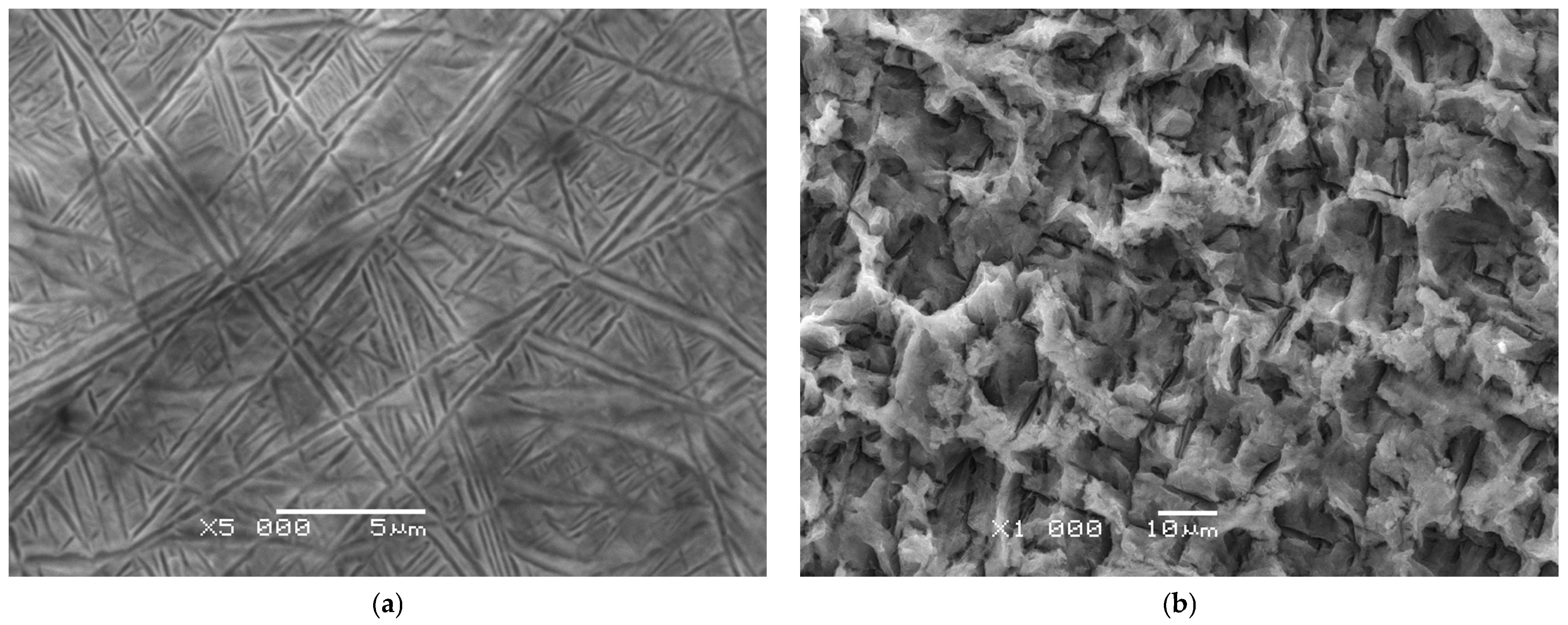
The microstructure of the Ti-13Nb-13Zr alloy prior to anodizing shown in
Figure 2a exhibits a typical biphasic composition consisting of a mixture of α and β phases [
8,
48,
49]. The etching process using Kroll’s reagent helped to reveal the microstructural details by selectively dissolving certain phases and enhancing the contrast between them [
43]. The observed SEM image reveals the presence of characteristic thin needles and bands arranged at various angles, forming a network of intersecting structures. This morphology indicates the dominance of α″ martensitic phases with an orthorhombic structure, formed as a result of the β phase transformation during cooling. Numerous martensitic twins are also visible, manifested as lines and bands with different crystallographic orientations. Their presence confirms the intensive β → α″ martensitic transformation, which is typical of titanium alloys stabilized with niobium and zirconium. The α″ needles and bands have a thickness on the order of hundreds of nanometers and a length of several micrometers, and their arrangement in different directions gives the microstructure a complex, network-like character. The structure is homogeneous, without large precipitates of a second phase, which indicates the dominance of the orthorhombic α″ phase throughout the sample volume. This microstructure of Ti13Zr13Nb after etching is typical of β-titanium alloys containing Nb and Zr, in which rapid cooling leads to the formation of orthorhombic α″ martensite. This arrangement of phases contributes to the alloy’s unique combination of strength, ductility, and biocompatibility, making it suitable for biomedical applications such as implants [
8].
SEM image presented in
Figure 2b provides a detailed view of the surface morphology of the Ti-13Zr-13Nb alloy after anodizing at 20 V for 120 min in an electrolyte composed of 1 M EG and 4 wt.% NaF. The surface exhibits a distinctly porous character, with irregular pores of varying size forming a network of depressions and elevations. The structure resembles a sponge-like oxide layer morphology, typical of titanium oxides formed during anodizing in the presence of fluoride ions. The pores range from several hundred nanometers to a few micrometers and are distributed non-uniformly across the surface. The oxide layer is not homogeneous; both deeper cavities and denser compact areas are present, reflecting the mechanism of simultaneous local dissolution and reformation of oxide during anodizing. The microstructure of Ti13Zr13Nb after anodizing results from the competing processes of oxide growth and dissolution in the presence of fluoride. Such surface topography enhances bioactivity and promotes cell adhesion, which is especially relevant for biomedical applications. In addition to altering the surface morphology, anodizing affects the mechanical and tribological properties of the alloy, as shown in studies on similar materials [
50,
51,
52].
The presence of Zr and Nb in the Ti-13Zr-13Nb alloy significantly influences the properties of the resulting oxide layer. Both elements contribute to modifications in the structural and chemical characteristics of the oxide layer. Zr is well known for its ability to form stable and protective oxide layers [
50], while Nb plays a role in enhancing the electrical conductivity and chemical stability of the oxide layer [
51]. Anodizing is particularly effective for the Ti-13Zr-13Nb alloy due to the chemical reactivity of its constituent metals. The structure and properties of oxide layers are strongly influenced by controlled anodizing parameters such as voltage, duration, and electrolyte composition. The tailored oxide layers formed with NaF significantly increases the effective contact area with biological tissue, which can enhance osseointegration process and support drug delivery applications [
53,
54,
55].
3.2. Chemical Composition of Porous Oxide Layers on Ti-13Zr-13Nb Alloy
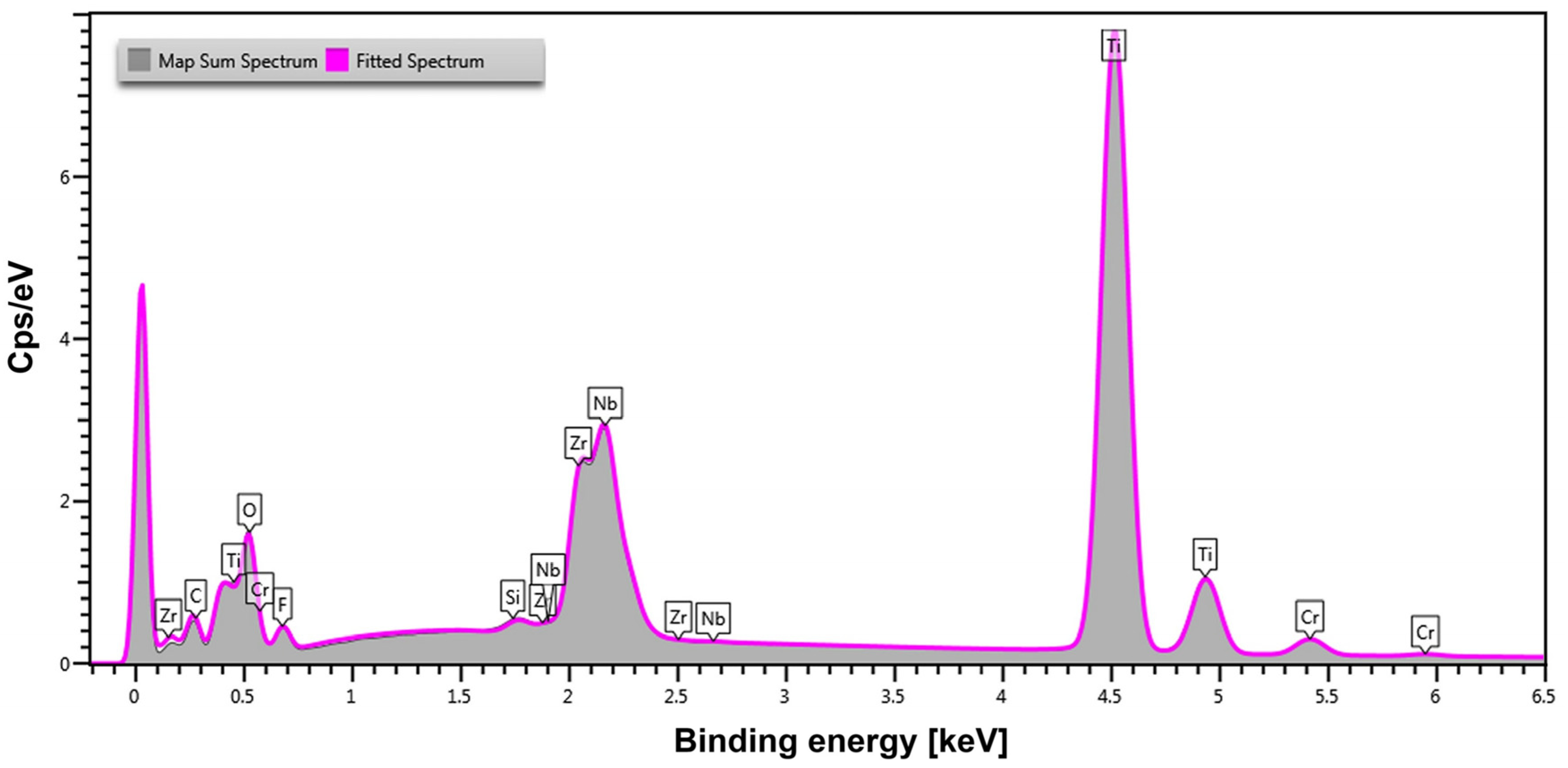
Quantitative analysis of the chemical composition of the Ti-13Zr-13Nb alloy after anodizing was conducted in selected micro-areas using the EDS method. An exemplary EDS spectrum of the anodically formed oxide layer is shown in
Figure 3. The presence and distribution of elements in the spectrum reflect the effect of anodizing on the chemical composition of the material surface.
Ti appears as the dominant peak, confirming its role as the primary constituent of the alloy. Zr, Nb, and O are also prominently detected, indicating the successful formation of an oxide layer as a result of anodizing. This suggests that surface oxidation occurred, leading to the development of a protective coating that enhances both corrosion resistance and bioactivity. The presence of C in the spectrum is likely due to residual EG from the anodizing electrolyte. F, originating from the NaF in the electrolyte, is also detected, indicating that fluoride ions were incorporated into the oxide layer. Such incorporation is known to improve the material’s biointegration and surface reactivity [
56]. Additionally, the spectrum reveals traces of Si, likely a result of environmental contamination, and small amounts of chromium Cr, which was sputtered onto the surface to improve electrical conductivity during SEM-EDS analysis.
According to
Table 1, Ti (44.1 wt.%) remains the predominant element, but its concentration is lower than in the untreated alloy [
8]. This reduction suggests the formation of a surface oxide layer covering the underlying Ti substrate.
The presence of Zr (8.5 wt.%) and Nb (8.2 wt.%) in similar proportions but at lower contents compared to the original alloy composition confirms that the oxide layer formed during anodizing contains Zr and Nb, probably as mixed oxides of these metals with titanium oxide. A significant O content (36.0 wt.%) confirms the formation of an oxide layer. The incorporation of fluoride ions (3.2 wt.%) suggests that the electrolyte composition with the NaF additive, has influenced the chemical structure of the oxide layer. The inclusion of fluorine is significant, as it enhances bioactivity, antibacterial properties, and osteointegration, making the material particularly suitable for biomedical applications.
3.3. Morphological Features and Deposition-Induced Structural Heterogeneity in CS-TC/Oxide Layer Hybrid Coatings
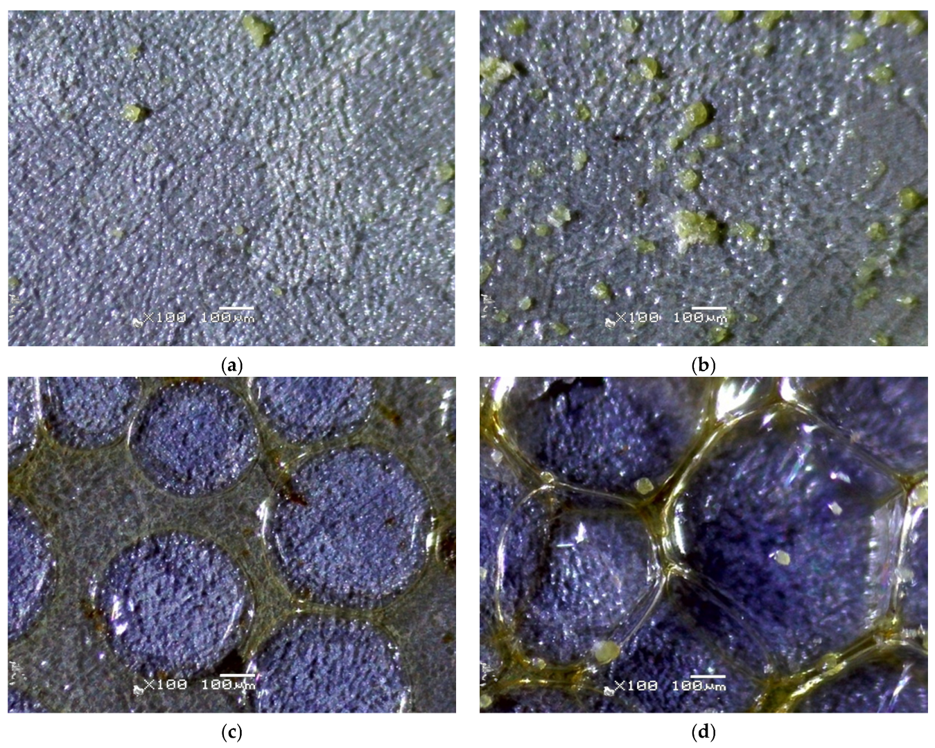
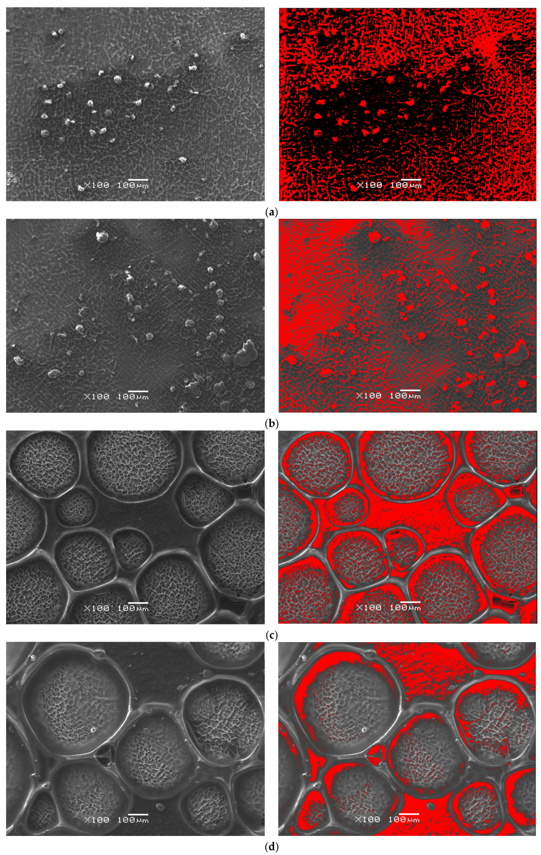
The results of optical microscopy analysis of the CS-TC coatings deposited on anodized Ti13Zr13Nb alloy are shown in
Figure 4. It can be observed that as a result of electrochemical oxidation, the color of the alloy surface changed from metallic to blue. The surface morphology of the DC1 coating deposited on porous oxide layer on Ti-13Zr-13Nb substrate in selected micro-region shows a rough and uneven texture, with noticeable graininess throughout the entire area, as shown in
Figure 4a. This roughness suggests inconsistent coating thickness or potential incomplete coating coverage during the DC process. Several scattered particles or aggregates, varying in size and distribution, are visible on the surface, with a yellow color indicating the presence of TC. Some areas show larger particle clusters, while others have fewer or no particles. These observations suggest that the dip coating process used for the 120 nm thick DC1 coating did not produce a fully consistent and uniform coating.
In the case of 360 nm thick DC3 coating deposited on anodized Ti-13Zr-13Nb substrate, the surface morphology exhibits noticeable roughness and irregularities (
Figure 4b). There are textured areas suggesting uneven coating formation, potentially caused by incomplete wetting or drying variations. Some scratches or cracks are present, which may indicate adhesion issues between the layers. The particle distribution analysis reveals an irregular dispersion of particles across the surface. Specifically, the bright regions in the thresholded image indicate areas of particle clustering. Certain sections exhibit higher concentrations, with a notable defect or contamination spot in the upper-right portion.
The edge detection results of the 3 µm thick EPD1 coating deposited on anodized Ti-13Zr-13Nb substrate at exemplary micro-region reveal significant surface irregularities, indicating non-uniform coating formation (
Figure 4c). Some regions display clear boundaries between deposited layers, which may suggest poor wetting or drying inconsistencies. Additionally, interconnected structures in certain areas are likely due to hydrogen bubble formation or uneven particle aggregation during deposition. The thresholded images highlight a non-homogeneous distribution of particles, with localized clusters and voids. Large circular formations suggest the presence of hydrogen bubbles or phase separation in the coating process. Some areas exhibit high particle concentration, while others appear depleted, indicating uneven EPD. During the EPD of CS coatings, hydrogen evolution occurs due to water reduction at the cathode, where the electrochemical reaction takes place:
During electrolysis in aqueous environments with direct current, hydrogen bubbles generated at the cathode can become trapped in the depositing CS layer, leading to micropores and surface irregularities that increase coating porosity and may alter mechanical properties and permeability. The rise in OH− concentration from water reduction raises the pH near the cathode, causing CS to precipitate in alkaline conditions, which aids deposition. However, uncontrolled pH shifts can create inhomogeneities in the coating structure. Hydrogen release during CS EPD is inevitable, and its structural impact varies with deposition time, current intensity, voltage, and electrolyte composition.
The surface morphology of the 8 µm thick EPD3 coating deposited on anodized Ti-13Zr-13Nb substrate at selected micro-region exhibits a network-like structure with interconnected regions (
Figure 4d). There is a noticeable presence of polymerized or gel-like formations around particle clusters, indicating non-uniform surface coverage. The edge detection analysis reveals multiple fine irregularities along the surface, which could be micro-cracks or drying patterns. The presence of a significant defect area suggests possible delamination or impurity inclusion. The sample presents characteristic features of EPD, including interconnected structures and deposition in localized regions. The presence of polymeric films between the particles suggests incomplete drying or residual binder retention.
The CS-TC coating, applied on porous oxide layers, enhances stability and adhesion through mechanical anchoring within the pores, leading to micromechanical interlocking. The oxide layer serves as an intermediate layer, significantly improving adhesive bond strength and the overall stability and functionality of the coating. Hydroxyl (-OH) groups on the oxide surface form hydrogen bonds and electrostatic interactions with the amine (-NH2) groups of CS, resulting in improved adhesion due to a gradual change in properties at the substrate-coating interface.
3.4. Pore Architecture and Network Connectivity in CS-TC/Oxide Layer Hybrid Coatings
Results of computer analysis of porosity based on SEM images of the surface morphology of the CS-TC coating deposited on anodized Ti-13Zr-13Nb substrate are presented in
Figure 5.
The microscopic images reveal significant variations in porosity across the different coating techniques, which directly influence their structural integrity and protective performance. The DC1 coating exhibits a remarkably high porosity of 63.94%. This elevated porosity suggests a substantial presence of interconnected pores throughout the surface, which could severely compromise the coating’s mechanical strength and barrier properties. The extensive pore formation may lead to increased permeability, reducing the coating’s effectiveness in providing protection against environmental factors.
In comparison, the DC3 coating, with a porosity of 29.79%, shows a moderate level of porosity. While this is lower than that of DC1, the presence of numerous small pores indicates some inconsistencies in the coating process. These inconsistencies could stem from variations in solution concentration, drying conditions, or coating thickness. Although the porosity level is lower than that of DC1, it still suggests a potential impact on the coating’s protective capabilities, albeit to a lesser extent.
The EPD1 coating, with a porosity of 31.98%, presents a unique case. While it has a higher porosity than DC3, the interconnected nature of the pores may still allow for some degree of mechanical integrity. However, the presence of these pores could still compromise the coating’s barrier effectiveness, particularly in environments where moisture or corrosive agents are present.
Finally, the EPD3 coating, with the lowest porosity of 21.04%, demonstrates a more favorable surface structure compared to the other coatings. This lower porosity suggests a denser coating with potentially better mechanical strength and protective performance. The reduced pore formation may enhance the coating’s ability to act as a barrier, providing improved durability and resistance to environmental factors.
The differences in microregions observed in the optical microscopy images arise from the deposition of CS-TC coatings on a porous surface with varying surface energy. Microregions exhibiting higher roughness within the pores may better anchor CS during EPD, as electrostatic forces drive particles into the pores. In contrast, coatings produced via DC may form a thinner liquid layer, which may not adhere as effectively within the pores, leading to non-uniform coverage. The porosity levels significantly influence the coatings’ performance, with lower porosity generally correlating with enhanced protective capabilities.
3.5. Surface Modification-Induced Mechanical Property Evolution in Ti-13Zr-13Nb Alloy
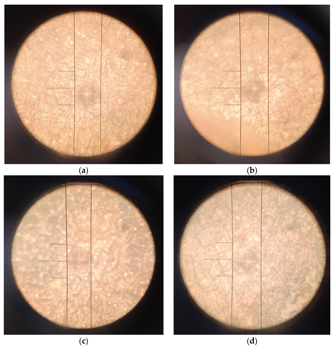
The representative micrographs presented in
Figure 6 illustrate the morphology of the Vickers indents formed during microhardness testing of the CS-TC coating deposited on anodized Ti-13Zr-13Nb substrate. It is clearly shown that EPD coatings exhibit smaller and more regular imprints compared to dip-coated samples, indicating higher hardness and improved mechanical integrity of the electrophoretically deposited layers. The transparent CS-TC coatings were not observed to be damaged or flaked under low loads. It should be note that in this study, CS with a high molecular weight of 80 kDa and a degree of deacetylation (DD) of 75–85% was used. As DD increases, the number of amino groups also increases, which strengthens the intermolecular bonds and improves the mechanical properties of CS, such as tensile strength and stiffness [
57]. Consequently, CS with a higher DD exhibits greater durability and flexibility. A higher DD in CS coatings on implants translates to better mechanical strength and increased wear resistance, enhancing the durability of the coating during use. Thus, coatings with a higher DD provide a more stable and robust coverage for implants, improving their integration with tissue and reducing the risk of delamination. Moreover, CS coatings were applied to the surface of the alloy in a hydrated form from an acetic acid solution, making it more flexible and softer. CS coatings deposited from an acetic acid solution exhibit good uniformity and appropriate cohesion, which affects their mechanical properties, such as hardness and wear resistance. Acetic acid ensures optimal dissolution of CS, promoting the formation of dense coatings with a stable structure, which translates into improved mechanical strength and better adhesion to the substrate, particularly on implants [
58].
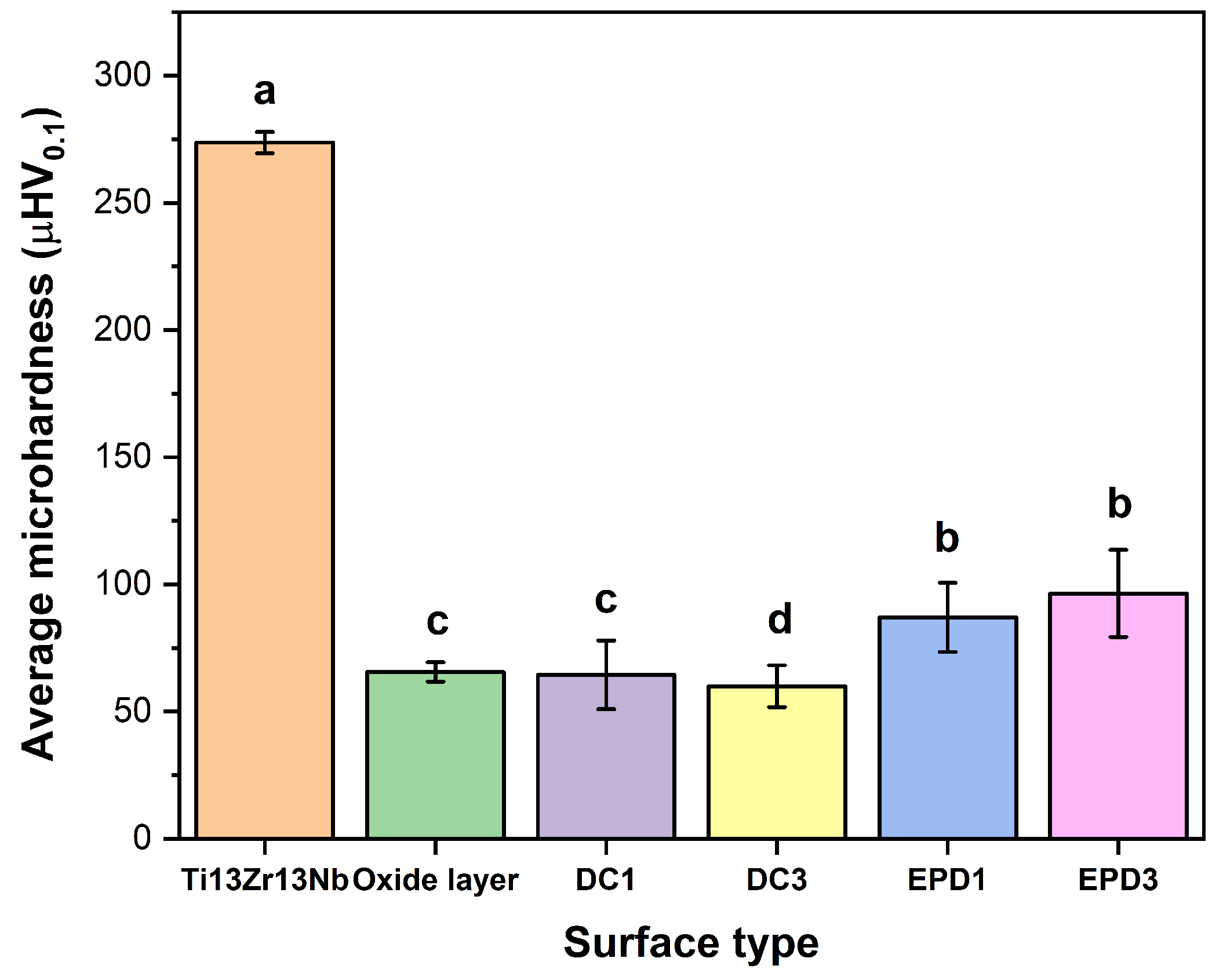
The results of micromechanical properties of the tested materials are illustrated in
Figure 7, which presents the average microhardness (µHV
0.1) of the Ti-13Zr-13Nb alloy in the initial state and its surface-modified variants, including porous oxide layer, DC1, DC3, EPD1, and EPD3 coatings.
The statistical analysis of the data from
Figure 7, assuming n = 10 measurements per group, confirms significant differences in microhardness between the unmodified Ti-13Zr-13Nb alloy and all surface-coated variants. A one-way ANOVA demonstrated extreme statistical significance (F = 122.4;
p < 0.00001), allowing rejection of the hypothesis that the group means are equal. Tukey’s post hoc test revealed that all coatings differ significantly from the base alloy (
p < 0.001), with the difference between the hardest state (Ti-13Zr-13Nb: 273.67 µHV
0.1) and the softest coating (DC3: 59.97 µHV
0.1) amounting to 213.7 µHV
0.1, corresponding to a ~78% reduction in hardness. A critical finding is the comparison between coatings: EPD3 (96.46 µHV
0.1) is significantly harder than DC3 (59.97 µHV
0.1)—the difference of 36.49 µHV
0.1 reaches statistical significance (
p = 0.0001), confirming the superiority of the EPD method in controlling mechanical properties. In contrast, the difference between EPD3 and EPD1 (87.01 µHV
0.1), at 9.45 µHV
0.1, is statistically insignificant (
p = 0.43), suggesting that modifying EPD process parameters (e.g., deposition time) does not substantially affect hardness. The high variability in EPD3 results (SD = 17.18 µHV
0.1) underscores the need for process optimization, such as stabilizing the suspension to reduce particle sedimentation heterogeneity.
In the biomedical context, these results have practical implications. The DC3 coating, despite its hardness being close to that of bone (30–80 µHV0.1), may be too soft for load-bearing implants, as evidenced by its significantly lower hardness compared to EPD3. Meanwhile, EPD3, while statistically indistinguishable from EPD1, offers a better compromise between bioactivity and wear resistance. Narrow confidence intervals for the base alloy (95% CI: ±2.97 µHV0.1) and oxide layer (±2.75 µHV0.1) confirm the high repeatability of these methods, whereas the wide interval for EPD3 (±12.31 µHV0.1) highlights the need for process refinement. Increasing the number of measurements from n = 5 to n = 10 improved estimation precision—for example, the standard error for EPD3 decreased from ~7.7 to ~5.4 µHV0.1—but did not alter the direction of the conclusions.
The reduction in microhardness of CS-TC-oxide layer coatings does not directly translate to improved functional durability, and its impact depends on the application context and the degree of hardness reduction. A softer hybrid coating can act as a buffer layer, reducing localized stress concentrations at the implant-bone interface, thereby minimizing bone resorption risks and enhancing implant stability. Minor deformations in coatings with lower hardness may reduce shear stresses during micromotions, limiting layer delamination. However, excessive softness compromises the coating’s internal cohesion (e.g., DC3: 59.97 µHV0.1), increasing the risk of cohesive cracking or interfacial delamination even under low stress. Excessively low hardness often correlates with heightened porosity or structural heterogeneity, accelerating degradation and particle release, which may trigger inflammatory responses. A delaminated coating releases drugs uncontrollably (e.g., burst release), destabilizing therapeutic efficacy.
For cyclic loading applications (e.g., orthopedic implants), balancing flexibility and strength is critical. For instance, the EPD3 coating with higher microhardness exhibits superior resistance to chipping while retaining stress-absorbing capabilities [
59]. In CS-TC coatings, optimal microhardness must account for both controlled drug release (matrix-dependent) and mechanical stability. Excessive softness may lead to uncontrolled degradation and loss of adhesion to metallic substrates. Moderate hardness reduction can enhance biointegration and stress distribution, but extremely low values (e.g., DC3) critically compromise durability. Key to success is designing coatings with property gradients—softer surfaces for bioactivity and harder interfaces near the substrate for adhesion.
3.6. Interfacial Molecular Architecture and Chemical Bonding Networks in CS-TC/Oxide Layer Hybrid Coatings
The ATR-FTIR analysis of CS powder and TC provides insights into their molecular structures and interactions. Comparing the spectra of CS and TC, distinct peaks corresponding to different functional groups can be observed in
Figure 8.
The ATR-FTIR spectra of six samples (CS, TC, DC1, DC3, EPD1, and EPD3 coatings) shown in
Figure 8 exhibit common bands characteristic of functional groups [
60,
61,
62,
63]. Weak bands at 2900 cm
−1 are associated with aliphatic C-H bonds, while bands in the 1650–1580 cm
−1 range arise from C=O carbonyl vibrations and amide I and II modes. Bands in the 1150-1020 cm
−1 region are attributed to glycosidic -C-O-C- linkages, and those at 1600–1500 cm
−1 indicate the presence of aromatic rings and C-N vibrations in TC. In DC1 and DC3 coatings, shifts and weakening of the C-O-C bands at 1000–1150 cm
−1 suggest structural modification of CS through interactions with titanium, as evidenced by the presence of a Ti-O-related band below 800 cm
−1. In EPD1 and EPD3 coatings, the carbonyl bands at 1700–1750 cm
−1 and O-H bands at 3300–3500 cm
−1 are more pronounced, indicating stronger hydrogen bonding and higher functional group content. Differences in band intensity and transmission between DC and EPD coatings—such as stronger C=O and C-O bands in EPD—suggest that the EPD method produces more homogeneous and durable coatings due to enhanced electrostatic and covalent interactions, whereas DC results in a weakened CS structure and thinner layers. Titanium influences shifts in amide bands at 1600–1550 cm
−1 and weakens glycosidic bonds, confirming coating-substrate interactions. Consequently, EPD ensures better component integration and superior antibacterial properties compared to DC.
3.7. TC Release Kinetics and Diffusion-Controlled Transport Mechanisms in CS-TC/Oxide Layer Hybrid Coatings
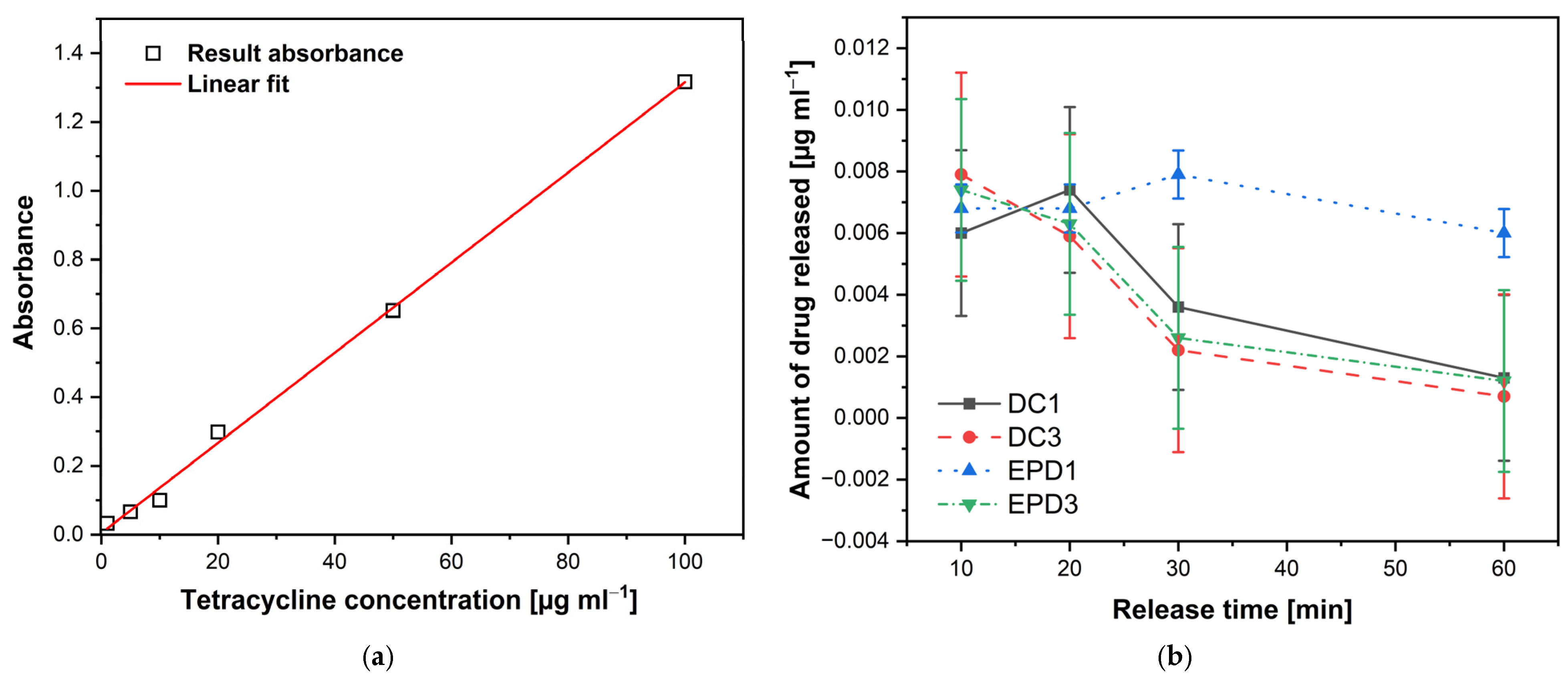
The release kinetics of TC from the deposited CS coatings were analyzed using UV–VIS absorption spectroscopy. A calibration curve was established for TC in PBS at 37 °C over a concentration range of 1–100 µg mL
−1 (1, 5, 10, 20, 50, and 100 µg mL
−1). The resulting calibration plot (
Figure 9a) showed a linear relationship between absorbance and concentration, with the regression equation y = 0.0131x + 0.0047 and a correlation coefficient R
2 = 0.9979. This equation was subsequently used to determine TC concentrations released from the CS–TC/oxide layer hybrid coatings (DC1, DC3, EPD1, and EPD3) on the anodized Ti–13Zr–13Nb substrate (
Figure 9b). The high linearity confirms that the Beer–Lambert law was obeyed within this concentration range [
64], ensuring accurate quantification of TC release.
It can be seen in
Figure 9b that at 10 min, the amount of TC released is relatively similar across all coatings tested, ranging from 0.0060 to 0.0079 µg mL
−1. This suggests that, initially, all coatings allow for a comparable level of drug diffusion. At 20 min, the release behavior starts to diverge. DC1 coating reaches its peak release at 0.0074 µg mL
−1, while EPD3 and DC3 coatings start showing a slight decline, particularly DC3 coating (0.0059 µg mL
−1). This indicates that dip coating with a single layer (DC1) facilitates a faster release compared to the other methods. By 30 min, a more pronounced difference appears in the release profiles. EPD1 coating maintains a relatively high release (0.0079 µg mL
−1), while EPD3 and DC3 coatings show a sharp decrease (0.0026 µg mL
−1 and 0.0022 µg mL
−1, respectively). This suggests that coatings with multiple layers (EPD3 and DC3) reduce the TC diffusion rate over time. At 60 min, the decline continues, with DC3 coating exhibiting the lowest drug release at just 0.0007 µg mL
−1. EPD1 coating still releases a moderate amount (0.0060 µg mL
−1), indicating a sustained release profile. EPD3 and DC1 coatings also show significantly reduced release rates (0.0012 µg mL
−1 and 0.0013 µg mL
−1, respectively).
It should be noted that the maximum TC release concentration from the CS–TC coatings (~0.008 µg/mL) was below the commonly reported minimum inhibitory concentration (MIC) values for most bacterial strains (0.1–5 µg/mL). This is likely due to the relatively low initial drug loading, strong interactions between TC and the CS matrix, and the limited release medium volume used in these experiments. Despite this, sub-MICs of TC can still contribute to antibacterial effects by reducing bacterial adhesion, inhibiting quorum sensing, and modulating inflammatory responses [
65]. Furthermore, the inherent antibacterial properties of CS complement the function of TC, providing a synergistic effect that may help prevent early-stage bacterial colonization. The current release profile may not be sufficient for complete bacterial inhibition. To overcome this limitation future work will focus on increasing drug loading and tuning release kinetics through strategies such as multilayer EPD, pH-sensitive crosslinking, or incorporation of nanocarriers to achieve local concentrations closer to the bacteriostatic threshold, while maintaining coating stability and biocompatibility.
Although direct antibacterial tests were not performed in this study, the antibacterial and anti-inflammatory potential of the CS–TC coatings is supported by the established activity of both components. The development of CS-TC/oxide layer hybrid coatings on anodized Ti-13Zr-13Nb is in its early stages, with significant potential applications. Future research should prioritize optimizing the coating process, assessing long-term biocompatibility, and performing in vivo studies to evaluate the efficacy and safety of these drug delivery systems. Incorporating advanced techniques such as molecular switches and peptide design could enhance the targeting and effectiveness of these drug carriers, maximizing the potential of CS coatings on anodized Ti-13Zr-13Nb alloy for clinical applications in implants and tissue engineering. Future work will also include in vitro and in vivo evaluations of the biological response to these coatings.
4. Conclusions
Porous oxide layers containing Ti, Zr, and Nb oxides with fluoride incorporation were successfully fabricated on Ti-13Zr-13Nb alloy via a novel anodizing process. The fluoride-assisted mechanism and resulting surface morphology were confirmed by SEM and EDS analyses. The anodized surfaces showed reduced microhardness, which may help mitigate stress-shielding effects in biomedical applications.
Chitosan–tetracycline coatings produced by electrophoretic deposition (EPD) demonstrated more uniform coverage, controlled porosity, and improved microhardness compared to dip-coated (DC) layers. These features qualitatively suggest better adhesion of EPD coatings, as supported by the more regular Vickers microhardness imprints and coating integrity observations.
Drug release studies indicated that EPD coatings provide a sustained release of tetracycline over 60 min, while DCs exhibit a rapid initial release. This tunable release profile highlights the potential of EPD coatings for acute and medium-term therapeutic applications.
The combination of anodized oxide layers and EPD chitosan–tetracycline coatings enhances surface functionality, mechanical performance, and drug delivery capabilities, making the system a promising candidate for regenerative medicine and antibacterial implant applications.
Future research should focus on improving drug loading capacity, validating antibacterial and biofilm inhibition properties, optimizing pore dimensions, and enhancing coating adhesion—potentially through plasma pretreatment—to support clinical translation of these surface modifications.
