Article

Study on the Adsorption Characteristics of Microbial-Reed Fiber and Its MICP Solidified Saline Soil Test

1
College of Civil Engineering and Water Conservancy, Qinghai University, Xining 810016, China
2
Qinghai Provincial Key Laboratory of Building Energy-Saving Materials and Engineering Safety, Xining 810016, China
*
Author to whom correspondence should be addressed.
Appl. Sci. 2025, 15(20), 11198; https://doi.org/10.3390/app152011198
Submission received: 11 September 2025 / Revised: 14 October 2025 / Accepted: 15 October 2025 / Published: 19 October 2025
(This article belongs to the Special Issue Advanced Technology in Geotechnical Engineering)

Abstract

In response to the issues of increased brittleness and insufficient toughness in microbially solidified saline sandy soils in cold and arid plateau regions, this study investigated saline sandy soils and indigenous microorganisms from the Qaidam Basin, Qinghai. A dual-reinforcement method combining microbial-induced calcium carbonate precipitation (MICP) with alkali-modified reed fiber (ARF) was proposed to enhance both strength and ductility. The study explored the adsorption characteristics and solidification mechanisms of this approach. Key innovations include: (1) alkali modification significantly improved the interfacial bonding between reed fibers and sand particles, with pull-out tests indicating a 1.24-fold increase in adhesion strength; (2) an orthogonal experimental design identified optimal parameters—fiber length of 15 mm, fiber content of 0.5%, and cementation solution concentration of 3 mol/L—leading to the development of a synergistic “microbial cementation–fiber bridging” enhancement model. Experimental results showed that the proposed method increased the unconfined compressive strength (UCS) of the solidified soil to 2082.85 kPa, 2.99 times higher than that of traditional MICP-treated soil, while it significantly enhanced the ductility of the soil. This approach offers a mechanically robust and environmentally adaptive solution within the ambient temperature range of 0–35 °C for the ecological restoration of saline soils in high-altitude regions.

1. Introduction

Saline soil is characterized by distinct engineering geological properties including salt expansion, dissolution, and corrosion. This type of soil typically develops at depths of up to 30 m beneath the surface engineering construction layer [1]. Globally, saline soil is expanding at an annual rate of approximately 10,000 to 15,000 km2 [2,3]. In China, saline silt is predominantly found in the cold and arid regions of the northwest and northeast, leading to a series of detrimental effects on engineering foundations such as subgrade salt swelling and collapse, slope salt erosion and failure, and salt crystallization damage to building foundations. These issues pose significant threats to both engineering integrity and ecological security [4,5]. Traditional physicochemical solidification methods exhibit several limitations including high costs, lengthy processing times, poor responsiveness, and the potential for secondary pollution of the geotechnical environment [6,7,8]. In contrast, the recently developed technique of microbially induced carbonate precipitation (MICP) offers a novel approach to soil solidification, resulting in notable improvements in mechanical stability and chemical activity compared with conventional methods. While MICP can enhance soil strength, it is associated with challenges such as uneven CaCO3 precipitation and brittle failure behavior [9,10,11,12]. Although the use of pure microbial-induced calcium carbonate precipitation is environmentally friendly, the resulting solidified soil tends to be brittle and ill-suited for complex stress environments, exhibiting significant brittleness and uneven distribution of calcium carbonate. Recent advancements in fiber reinforcement technology have demonstrated its potential to enhance soil toughness. However, prior research has primarily concentrated on synthetic or man-made fibers, which often incur high costs and may pose health and environmental risks [13,14]. The high salinity, freeze–thaw cycles, and other environmental stresses present in cold, dry saline soils on plateaus inhibit strain activity, resulting in inadequate adhesion at the fiber–soil interface and poor resistance to salt and alkaline conditions. Consequently, establishing an ecological mechanical synergistic enhancement mechanism to overcome the limitations of singular technologies has emerged as a critical challenge for improving saline soils in plateau regions. Phragmites australis, a plant abundant in alpine saline-alkaline humid environments, possesses fibers that are low-cost, environmentally friendly, and exhibit favorable mechanical properties including high stiffness, strength, and toughness [15,16].
This article seeks to address the limitations identified in previous research by concentrating on saline-alkali soils and indigenous microorganisms within the cold and arid region of Qinghai. It investigates the synergistic solidification mechanisms and pathways for performance optimization that arise from the integration of alkali-modified reed fibers (ARF) and microbially induced calcite precipitation (MICP) technology. Utilizing pull-out tests, the study reveals the evolution of bonding strength at the fiber–soil interface and conducts a comprehensive analysis of the interactions among various factors including fiber length, dosage, surface roughness, MICP cementation liquid concentration, and soil dry density. This analysis elucidates the synergistic enhancement mechanisms of biocalcification and fiber reinforcement, thereby establishing a dual-effect solidification system characterized by “microbial cementation-fiber toughening.” The findings of this research offer a theoretical foundation and technical support for the ecological restoration and engineering reinforcement of saline-alkali soils in cold and arid regions, thereby contributing to the advancement of green geotechnical engineering in alignment with the “dual carbon” objectives.

2. Overview of the Research Area

The research area is located in the central part of the Qaidam Basin on the Tibetan Plateau (Figure 1a). The average altitude of this region reaches 3350 m, and the climate is extremely arid, with an average annual rainfall of only 41.5 mm, while the annual evaporation exceeds 3000 mm. The surface is characterized by saline soils that cover an area of approximately 1.57 × 10⁴ km2 and are distributed discontinuously (Figure 1b). In the low-lying areas, large expanses of salt-tolerant plants such as wild reeds and goji berries grow (Figure 1c).

3. Experimental Materials and Methods

3.1. Experimental Materials

3.1.1. Basic Physical and Chemical Properties of Saline Soil

The Qaidam Basin in Qinghai is located in a cold and arid climate zone, and its unique geographical environment has given rise to typical saline sandy soil. The soil sample appears yellow-brown, with fine and evenly distributed particles, and salt particles and sporadic salt crusts can occasionally be seen on the surface. Soil samples were collected from four exploration wells (denoted as TJ1–TJ4) within the study area. For particle size determination, the dry sieving method was adopted in accordance with the Chinese national standard for geotechnical test methods (GB/T 50123-2019) [17], which is well-suited for the coarse-grained saline sandy soil in this region. Considering the high salt content and occasional salt crusts (a common feature of Qinghai saline soil), the soil samples were pretreated as follows: (1) soluble salts were removed by leaching with deionized water until the leachate showed a conductivity < 100 μS/cm to avoid salt crystallization binding soil particles into aggregates; (2) samples were dried at 55 ± 5 °C to prevent thermal damage to soil particles while avoiding residual salt melting, and then gently crushed with a rubber pestle to break up loose aggregates formed by freeze–thaw cycles, a key environmental factor in high-altitude areas; (3) impurities such as plant residues and gravel > 2 mm were manually removed. After pretreatment, the samples were sieved using a standard sieve set with mesh sizes of 0.9 mm, 1.0 mm, 1.15 mm, 1.2 mm, and 2.0 mm, focusing on the particle size range relevant to the study. The sieve shaker was operated at a frequency of 50 Hz for 15 min to ensure complete separation. Through the analysis of the grading curve of the saline sandy soil in the study area (Figure 2), it was found that the particle size was mainly concentrated in the range of 1.00 to 1.13 mm. Further calculations showed that the uniformity coefficient of the soil sample was 2.067, and the curvature coefficient was 0.993, indicating that this saline sandy soil had the characteristics of uniform particles but poor grading. The particle size of the saline sandy soil was concentrated between 1.00 and 1.13 mm, demonstrating a high degree of uniformity.
In addition, the specific gravity of the soil particles (Gs) was 2.673, the dry density in its natural state was 1.676 g/cm3, the natural moisture content was 1.063%, and the pH value stabilized in the range of 8.15, which is consistent with the basic characteristics of weakly alkaline geological media. Furthermore, particle size analysis indicated significant defects in gradation continuity (Cu = 5.32, Cc = 1.08); tests confirmed that the soluble chloride salt content reached as high as 1.244% (mass fraction), constituting a typical saline corrosion environment. The compression curve showed that its compression index Cc < 0.2, categorizing it as low compressibility soil. Based on a comprehensive analysis of the geotechnical parameter system, it can be classified as a medium chloride salt type saline sandy soil with potential for dissolution, strong corrosiveness, and loose structure (Table 1).

3.1.2. Reed Fiber Modification Process

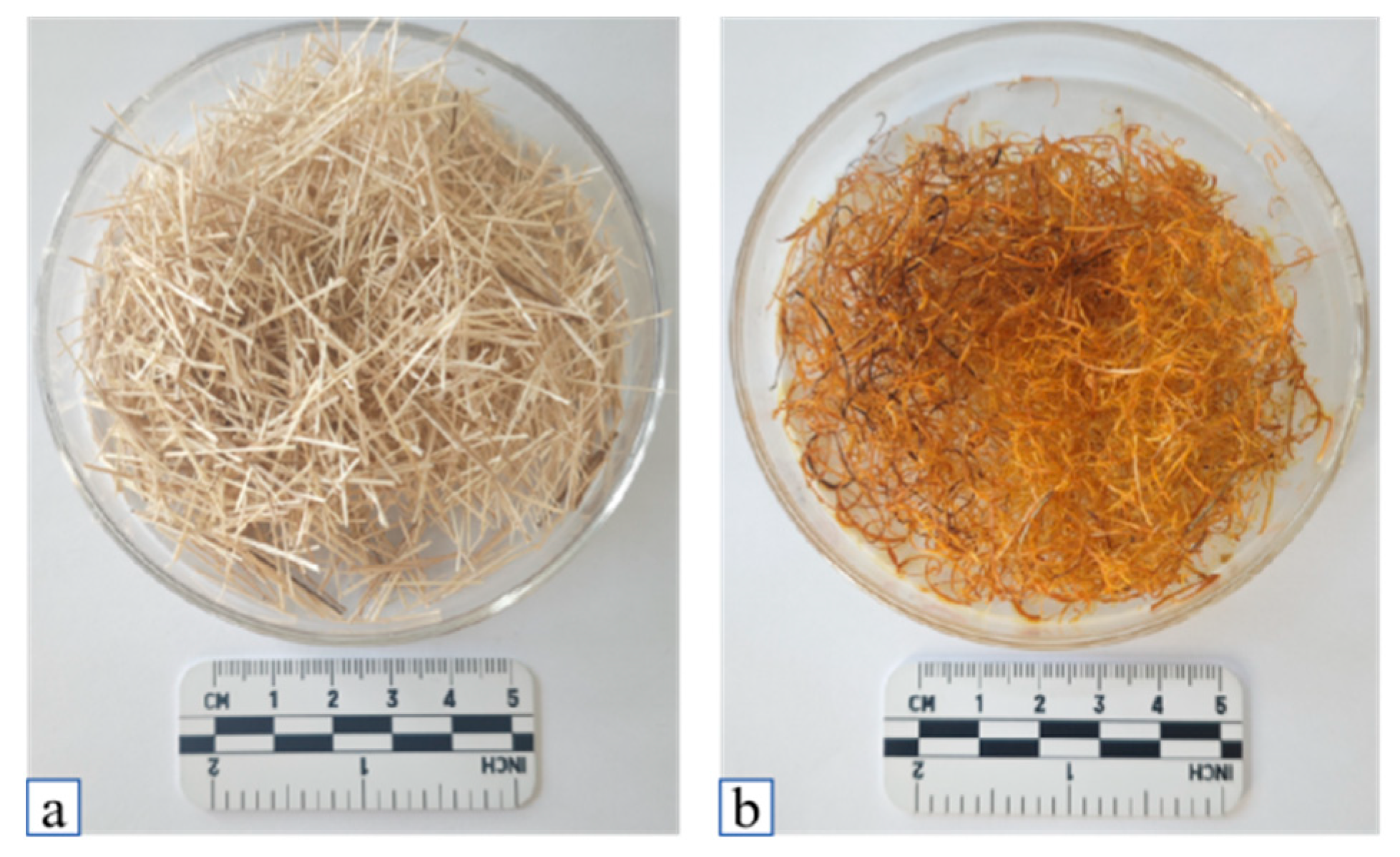
Reeds were collected from the Qaidam Salt Lake wetland in Qinghai, and after cutting → alkali treatment (1 M NaOH, soaked in a water bath at room temperature 25 ± 2 °C for 2 h) → ultrasonic cleaning → drying (constant temperature at 60 °C for 48 h), modified fibers (ARF) were obtained, while unmodified fibers (URF) were used as the control group [18] (Figure 3).
Previous studies have shown that the strength of fiber-reinforced soil largely depends on the fiber length and fiber ratio [19,20]. Therefore, reed fibers were cut into lengths of 10 mm, 15 mm, 20 mm, 25 mm, and 30 mm for experimental materials, and their physical properties were tested (Table 2).

3.1.3. Test Microorganisms

This research involved the selection of indigenous salt-tolerant ureolytic microorganisms (A80) from the Qaidam Basin in the Tibetan Plateau, Bacillus pasteurii (American Type Culture Collection number ATCC11859, Manassas, VA, USA, hereafter referred to as “Bp”) and another strain of Sporosarcina pasteurii (American Type Culture Collection number ATCC11859, Manassas, VA, USA, hereafter referred to as “Sp”). For large-scale cultivation, Tryptic Soy Agar (TSA) medium was employed (Table 3). Prior to inoculation, the sterilized medium was allowed to cool to room temperature (20 ± 1 °C) within a clean bench environment. Subsequently, the strains were inoculated and incubated under shaking conditions at 35 °C and 180 r/min for a duration of 64 h to facilitate strain enrichment. The cultures were then retrieved for future applications.

3.2. Experimental Design

A four-factor, three-level orthogonal experiment (L9(34)) was executed, incorporating the following variables:
  • Fiber length (A): 10, 15, 20, 25, and 30 mm;
  • Fiber content (B): 0.1%, 0.2%, 0.3%, 0.4%, and 0.5%, and 0.6% (mass ratio);
  • Initial dry density (C): 1.405, 1.457, and 1.510 g/cm3;
  • Binder solution concentration (D): 1.0, 2.0, and 3.0 mol/L.
For each experimental group, three parallel samples (Φ39.1 mm × H80 mm) were prepared, with the soil-fiber mixture layered in accordance with the specified dry density. A peristaltic pump was employed to sequentially inject the bacterial solution and the binder solution, which consisted of a mixture of urea and anhydrous calcium chloride in a molar ratio of 1:1. The samples were subsequently cured at a controlled temperature of 25 ± 2 °C for a duration of 7 days.

3.2.1. Determination of Strain Enzyme Activity

Based on the environmental conditions of the cold and arid region of the Qinghai Plateau, the urease activity values (abbreviated as U) of three strains, A80, Ba Gan, and Ba Qiu, were measured using a multifunctional enzyme labeler (Thermo Scientific™ Varioskan LUX, Thermo Fisher Scientific, Waltham, MA, USA) under conditions of 5% salt concentration at environmental temperatures of 0 °C, 5 °C, 15 °C, 25 °C, and 35 °C, observing the changes over time.

3.2.2. Calculation of Microbial Strain Retention Rate

The determination of microbial strain retention rate can reflect the adsorption of injected bacteria in the sand column, and since the retention status can affect the solidification process, it can be used to predict the reinforcement effect. Before injecting the bacterial solution, the OD600 value of the bacterial solution is measured as n1. After the injection is completed, the outflow liquid is collected from the top, and the OD600 value of the collected outflow liquid is measured as n2. The bacterial adsorption rate S of the sand column is calculated using Formula (1) and the average value is taken.
S = [(n1 − n2)/n1] × 100%

3.2.3. Microbial Adsorption Capacity Test for Calcium

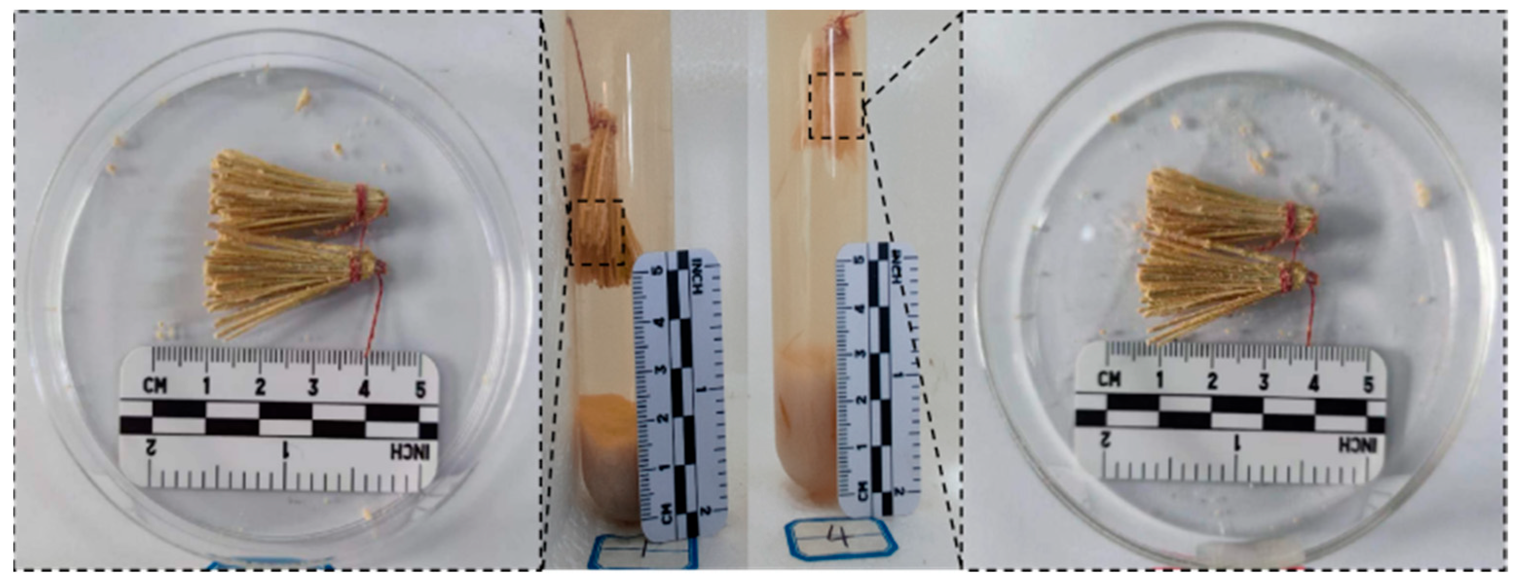
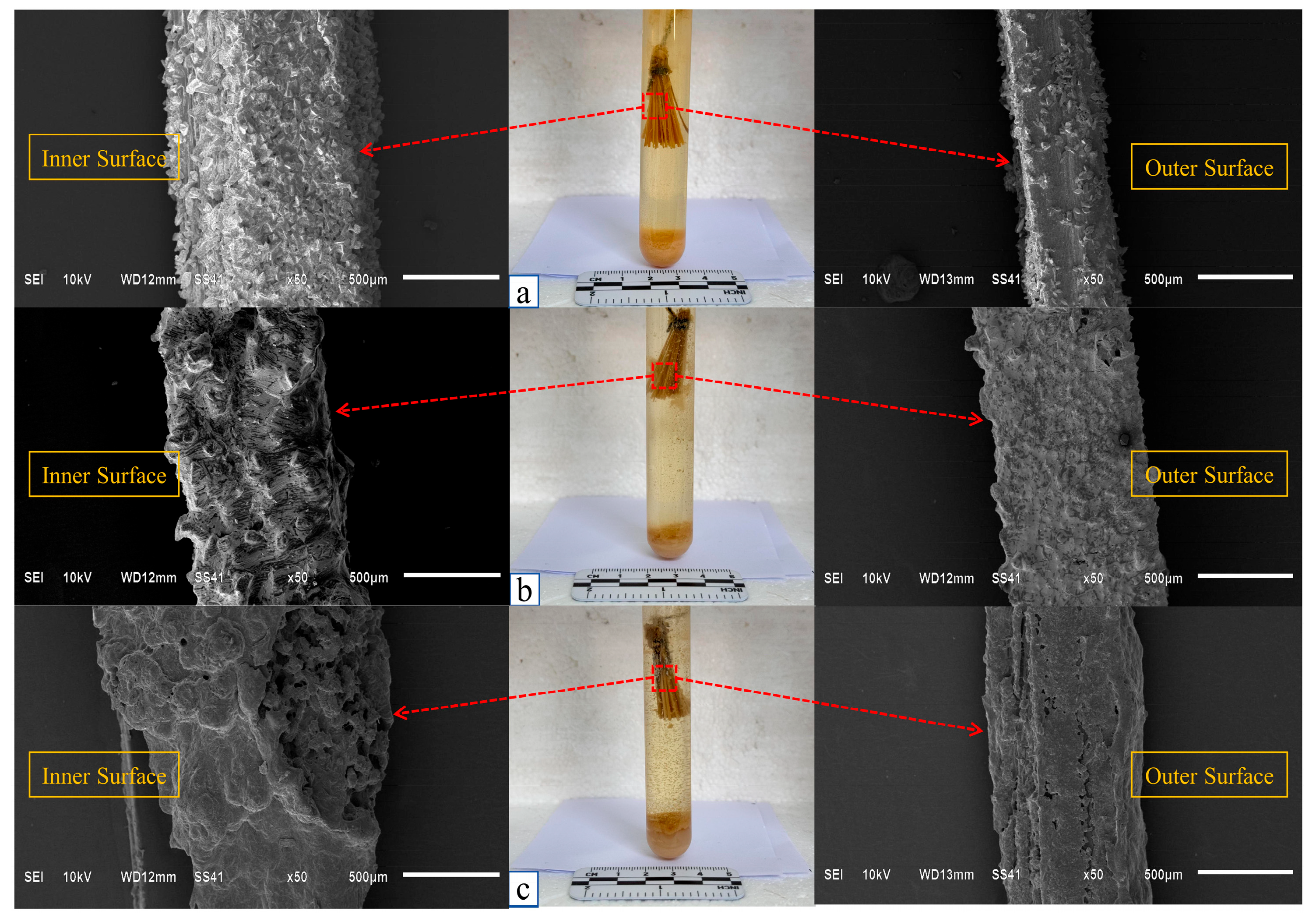
Inoculate the strains in a 5% salt concentration TSA liquid medium and incubate at 35 °C for 24 h. After that, tie 0.1 g of high-temperature sterilized reed fiber (30 mm) with a string and place it in the center of the bacterial liquid (15 mL). Continue to incubate for 56 h until the enzyme activity reaches its optimal moment. Then, take 15 mL of the cementation solution (a mixture of 15 mL of 1 M, 2 M, and 3 M urea and anhydrous calcium chloride) and incubate at a constant temperature of 35 °C for 7 days. Afterward, remove the reed fiber, filter the white precipitate in the test tube, and dry it (Figure 4).
Subsequently, the weight and sediment morphology and composition of the adsorbed precipitate were determined using the weighing method, scanning electron microscopy, and mineral X-ray diffraction.

3.2.4. Interface Performance Test

A reed fiber was embedded in the sample, and after curing and drying with MICP, a pull-out strength test was conducted using an RWT-6010 microcomputer-controlled electronic universal testing machine (Wance, Shenzhen, China). The fiber was fixed with a clamp and pulled out at a loading rate of 1 mm/min (Figure 5). Three samples were tested for each group. The pull-out strength of the fiber can be determined by Formula (2) [21]:
τmax = Pmax/(WHL)
In the formula, τmax (MPa) represents the bonding strength; Pmax (N) is the peak pull-out force; W (mm) is the width of the reed fiber, taken as mm in this study; H (mm) is the thickness of the reed fiber, taken as mm in this study; L (mm) is the embedded length of the reed fiber, taken as mm in this study.

3.2.5. MICP Curing Test of Saline Soil Columns

For the prepared saline soil columns, the A80 microbial solution was injected from the bottom to the top, followed by the previously prepared grout solution. This was conducted through segmented multiple grouting to improve the uniformity of mineralization. The prepared soil column had a diameter of 39.1 mm and a height of 80 mm. The experimental environment temperature was controlled at 25 ± 2 °C, and the grouting rate was set at 1 mL/min, with grouting performed every 24 h. The soil columns were grouted a total of 7 times, cured for 7 days, and then dried before demolding the specimens.

3.2.6. Performance Test of Solidified Soil Mass

(1)
Unconfined Compressive Strength Test (UCS) and Unconsolidated Undrained Shear Strength Test (UU)
Following the demolding of soil column specimens treated through microbial induced calcite precipitation (MICP), the specimens were subjected to a drying process in an oven at a temperature of 100 °C for a duration of 24 h. Subsequently, the unconfined compressive strength test was conducted utilizing a YAW4306 microcomputer-controlled electro-hydraulic servo pressure testing machine (Wance, Shenzhen, China), with a predetermined strain rate of 1 mm/min. Upon completion of the curing period, the samples were dried and demolded, after which an unconsolidated undrained shear strength test was executed, employing a shear rate of 0.8 mm/min and a confining pressure of 100 kPa.
(2)
Quantification of Calcium Carbonate Content
Subsequent to the failure of the soil column during the unconfined compressive strength test, equal masses of soil (denoted as m1) were extracted from the upper, middle, and lower sections of the column to mitigate the influence of heterogeneous CaCO3 precipitation within the MICP-cured soil. Following comprehensive acid washing and drying, the mass of the soil sample was recorded as m2. The difference between m1 (initial sampled mass) and m2 (mass after acid washing and drying) is the mass of calcium carbonate in the soil. The calcium carbonate content present in the saline soil post-MICP curing can be determined using Formula (3):
C CaCO 3 = ( m 1 m 2 ) m 1 × 100 %

4. Results and Analysis

4.1. Growth Characteristics of A80 Strain in a Saline Environment

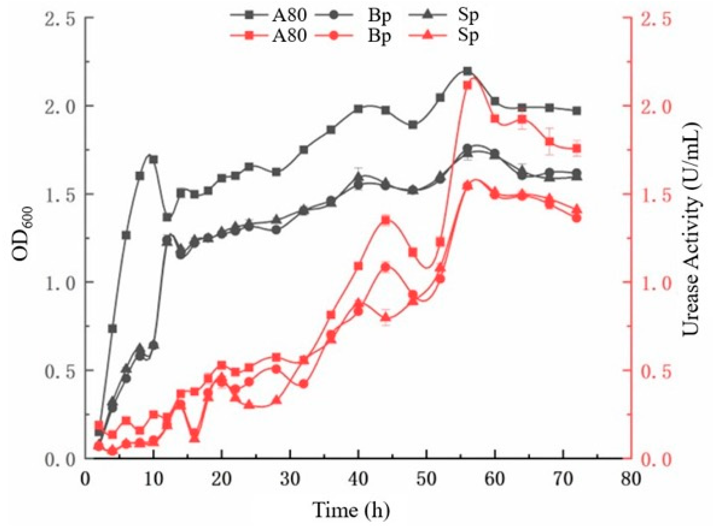
An ultraviolet spectrophotometer (V-1500, Shanghai Metash Instruments Co., Ltd., Shanghai, China) and multifunctional enzyme labeler (Thermo Scientific™ Varioskan LUX) were used to analyze the growth conditions and urease activity of A80, Bp, and Sp in a saline environment. The results indicate (Figure 6) that the growth of A80 can be divided into four stages: logarithmic growth phase (0–12 h), growth plateau phase (12–24 h), stable growth phase (24–56 h), and decline phase (60 h and beyond). At 12 h of cultivation, the growth of the A80 strain peaked, followed by a brief decline. This is mainly because the strain initially used glucose as the primary carbon source, and by 12 h, the glucose had nearly been depleted, prompting the bacteria to utilize other carbon sources (such as peptone). Furthermore, the growth curve of A80 did not completely align with the urease production curve; that is, urease production only begins to increase logarithmically after the strain enters the stable growth phase, indicating a certain lag in its urease production capability [22].
Figure 6 and Figure 7 indicate that under different temperature conditions, the urease activity of the three microorganisms showed a trend of first increasing and then slowly decreasing with the changes in the life cycle of the strains, and the overall urease activity weakened as the environmental temperature decreased. Among them, strain A80 outperformed Bp and Sp in terms of salt tolerance, urease production capacity, and low-temperature tolerance. When the environmental temperature was 35 °C, the urease activity of A80 was 2.116 U/mL, which was 1.370 times and 1.369 times that of Bp and Sp, respectively. When the temperature dropped to 0 °C, the urease activity of A80 still reached 0.569 U/mL, which was 2.647 times and 2.442 times that of the aforementioned two strains. In contrast, the enzyme activity of Bp and Sp decreased more significantly under low-temperature conditions, indicating that the indigenous strain A80 has a stronger adaptability to cold and arid climates as well as high-salinity environments.
In summary, it can be concluded that A80 has a superior urease production capacity compared with Bp and Sp, with the optimal time for seed culture being 16 h, the optimal time for fermentation culture being 24 h, and the optimal time for urease production culture being 56 h.

4.2. Effect of Fiber Surface Roughness on Calcium Carbonate Adhesion

4.2.1. Research and Analysis of Strain and Reed Fiber Adsorption

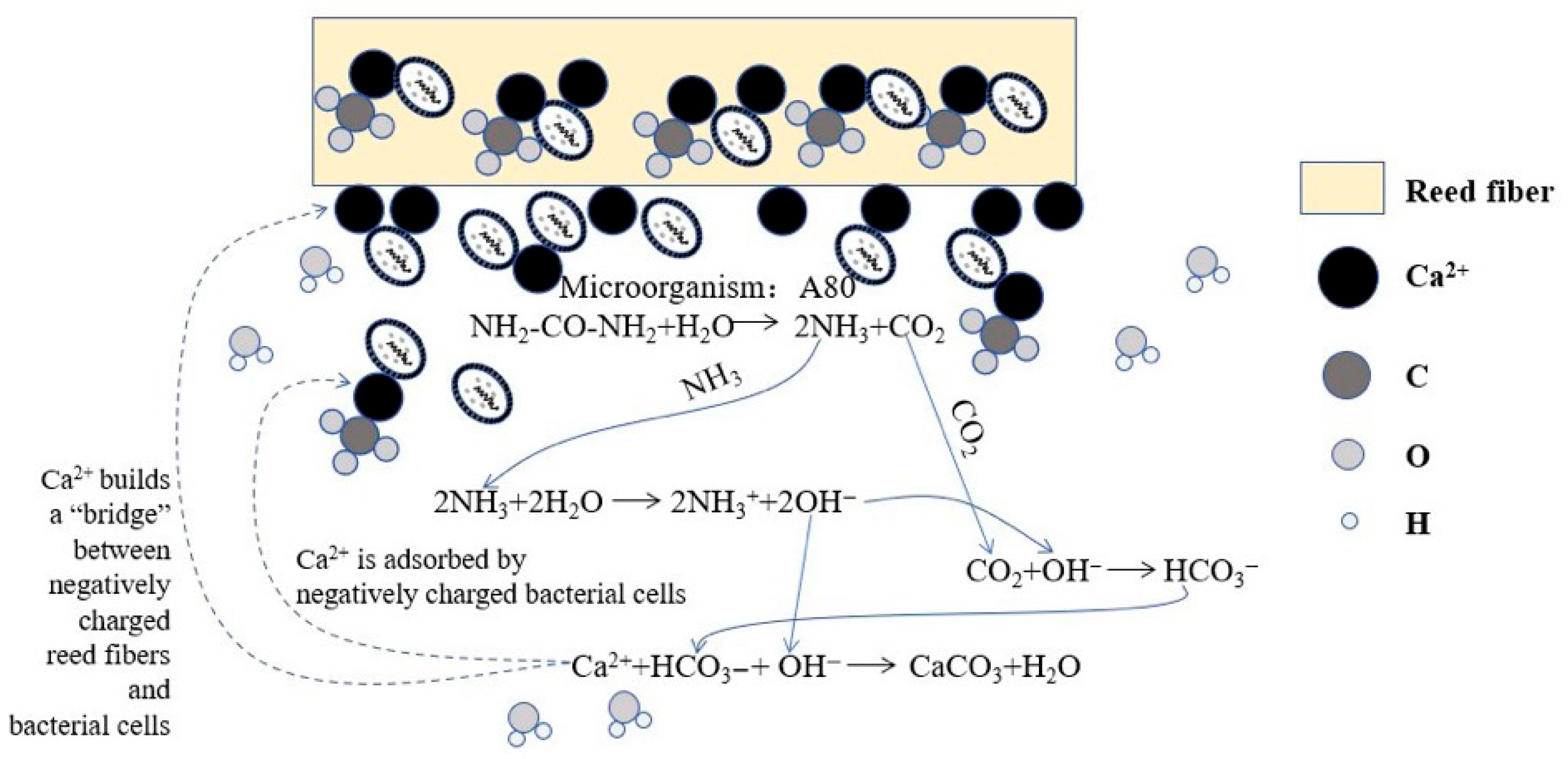
In alkaline solutions, the carboxyl and other acidic functional groups on the surface of reed fibers undergo dissociation, carrying negative charges. The isoelectric point of bacteria typically lies between pH 2 and 5; therefore, in alkaline environments, the carboxyl and other acidic groups on the surface proteins of bacteria also dissociate, resulting in a negatively charged cell surface. Although both reed fibers and bacterial surfaces carry negative charges, the uneven distribution of surface charges may lead to localized regions where positive and negative charges are relatively concentrated, thereby generating some electrostatic attraction. Additionally, multivalent cations (such as Ca2+ and Mg2+) present in the solution can act as a “bridge” between bacteria and reed fibers (Figure 8). These cations can simultaneously bind to the negative charges on both surfaces, effectively reducing the distance between them and promoting the adsorption process [23].
At the same time, there exists van der Waals forces between the bacteria and reed fiber, which can promote their mutual approach and adsorption within a short distance, and is a common physical interaction during the contact process between bacteria and reed fiber. Reed fiber has a typical filamentous structure, and bacteria may become attached to the fiber surface due to the physical entanglement effect while moving in solution, similar to how fibrous materials easily capture small particles. Additionally, bacteria can secrete extracellular polymeric substances during growth, which have certain adhesive properties, enhancing the interaction between the bacteria and reed fiber and further promoting the adsorption process [24].

4.2.2. Microanalysis of Calcium Adsorption by Strains

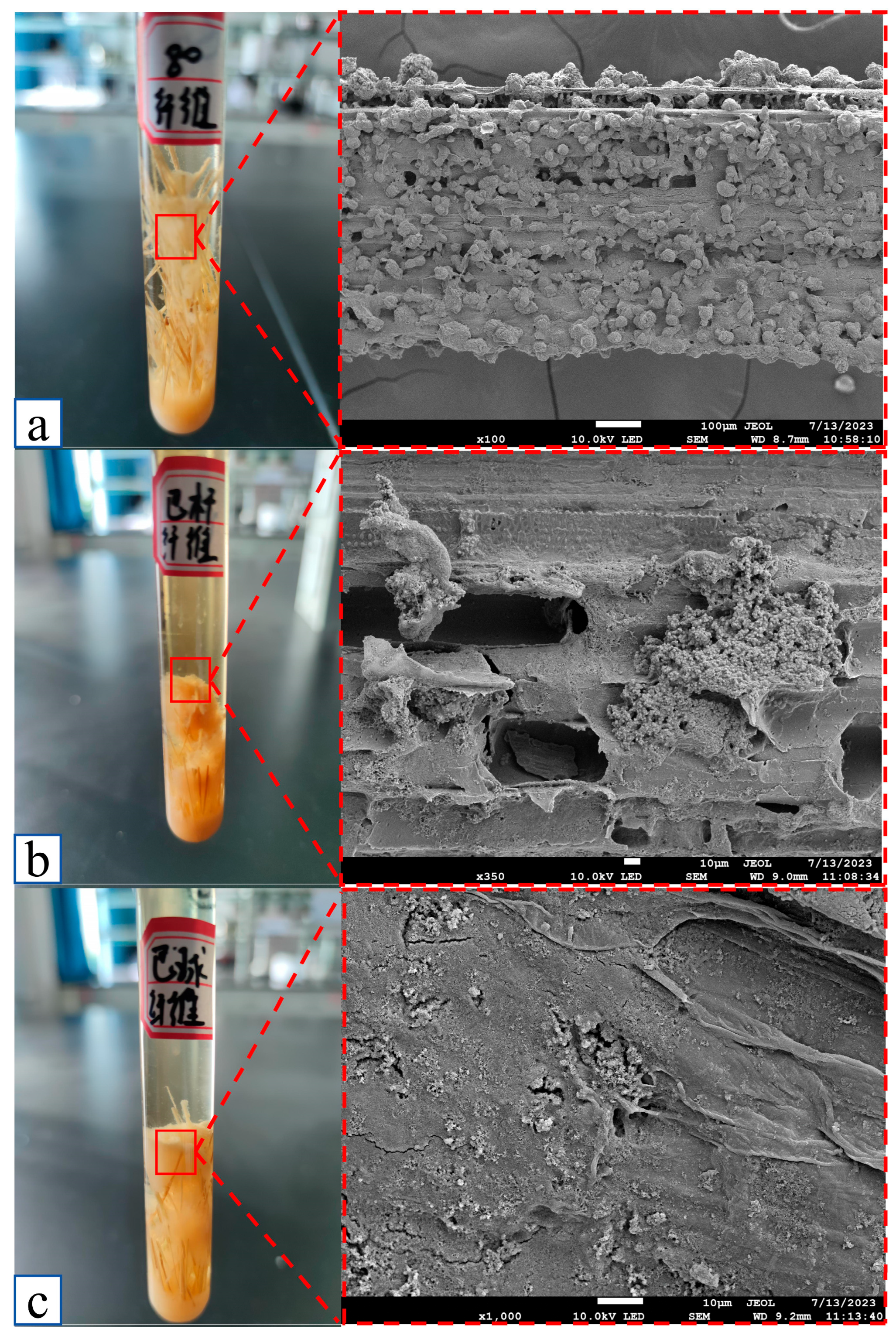
Using scanning electron microscopy (SEM) technology, the adsorption-induced calcium precipitation capabilities of A80, Bp, and Sp. sphere were analyzed in detail (Figure 9). The study revealed that under saline conditions, the A80 strain demonstrated exceptional adsorption-induced calcium precipitation capability, and its adsorption compatibility with the reed fiber reached an optimal state. Based on this, the use of the A80 strain in reinforced soil stabilization applications can achieve more desirable results, effectively enhancing the soil’s performance and stability.
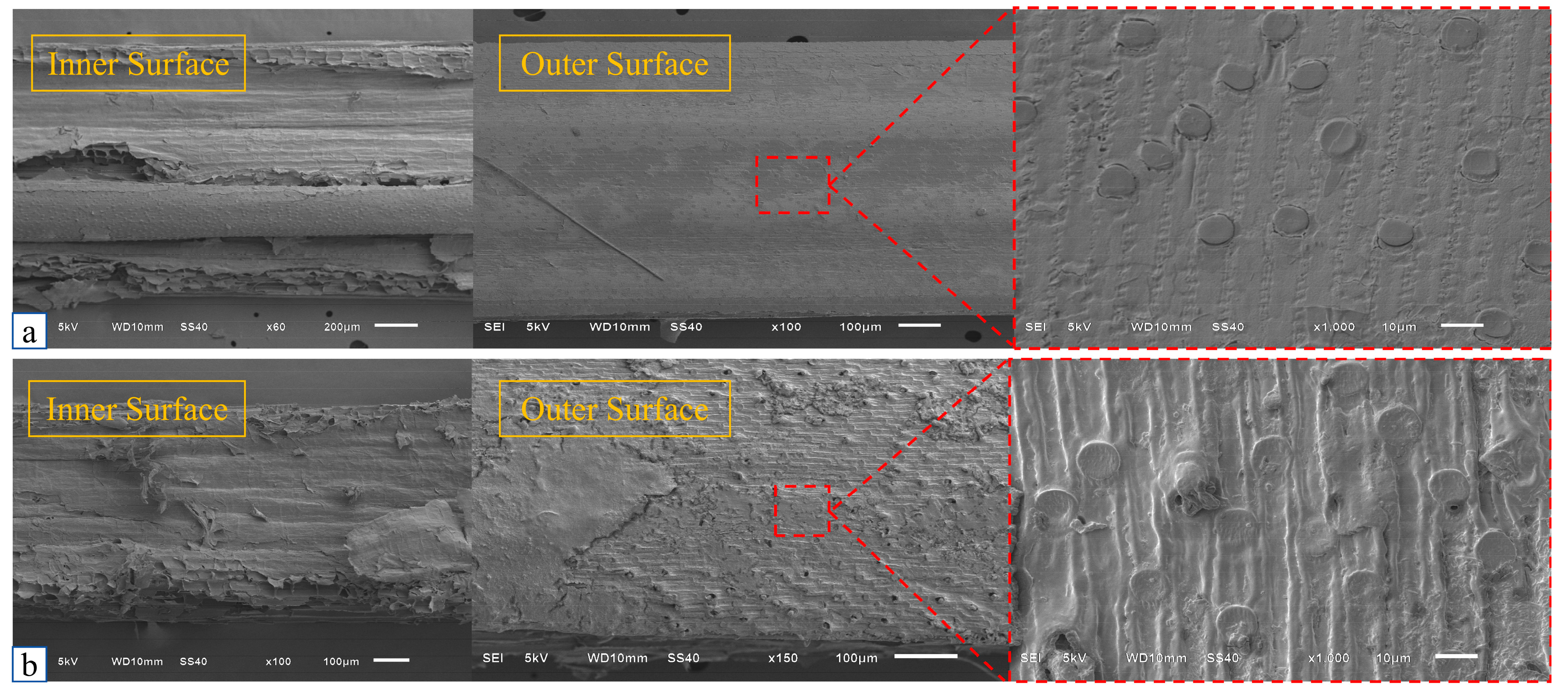
Since the distribution of the strains in the medium was relatively uniform, and their contact patterns and durations with the reed fibers were random, this provides certain conditions for the formation of CaCO3 (Figure 10); Figure 10a,b shows that the waxy layer on the outer surface of the reed fibers in the ARF group had been effectively removed, and the roughness of both inner and outer surfaces of the fibers increased, providing more attachment sites for bacterial adhesion.
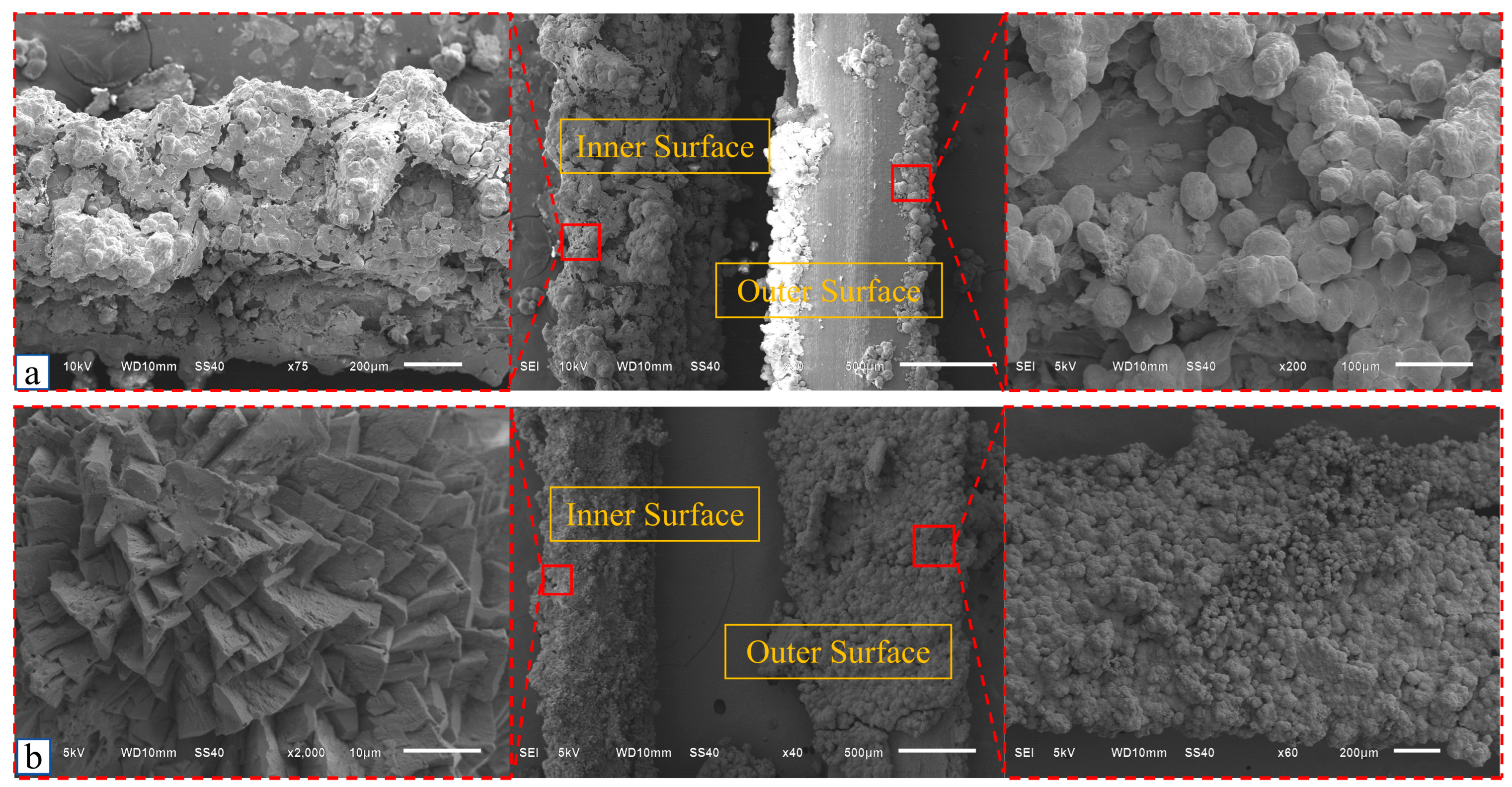
The reed fiber was suspended in the middle of the culture medium (Figure 9), effectively excluding the possibility of passive deposition of the strain on the fiber surface due to gravity. In the ARF group, the wax layer of the fiber was removed, and the surface roughness was increased, providing more attachment sites for the strain. This allowed the strain to slowly adsorb onto the fiber surface, resulting in a significant increase in the amount of calcium carbonate deposited on the outer side. Additionally, in the ARF group, Ca2+ and CO32− in the solution tended to precipitate and crystallize in the form of aragonite on the outer side of the fiber (Figure 11b). Further comparison showed that the CaCO3 on the inner side of the ARF group fibers mainly existed in the form of calcite, while the URF group was dominated by aragonite (Figure 11). This difference was primarily attributed to the fact that the surface roughness of both the inner and outer surfaces of the ARF group fibers was generally higher than that of the URF group (Figure 10), making it easier for the strain to adsorb onto both sides of the ARF fibers. The rapid attachment of the strain altered the local microenvironment of the fiber, thereby affecting the deposition rate and crystallization behavior of Ca2+ and CO32−, ultimately leading to differences in the morphologies of CaCO3 crystals on the fiber surface.

4.2.3. Comparison of Calcium Adsorption Amount Between URF Group and ARF Group

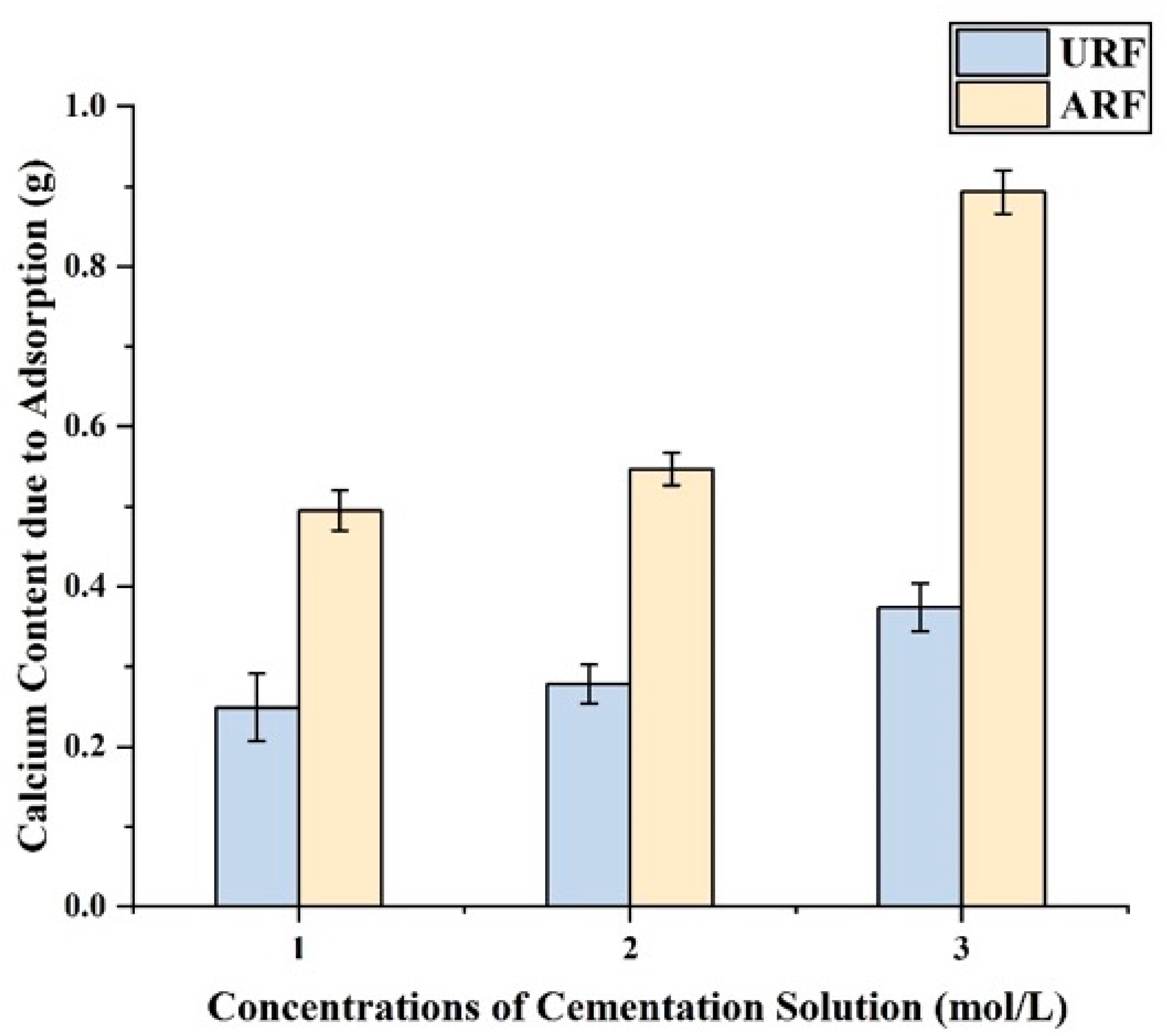
The analysis of the strain’s adsorption-induced calcification results (Figure 12 and Figure 13) showed that the adsorption-induced calcification amount of the ARF group was significantly higher than that of the URF group. Under different concentrations of the cementation solution, the adsorption-induced calcification amount of the ARF group increased by 98.795%, 96.763%, and 138.77% compared with the URF group, respectively, and the adsorption-induced calcification amount was positively correlated with the concentration of the cementation solution. Figure 13 provides a microscopic analysis, indicating that as the concentration of the cementation solution increases, the amount of calcium carbonate generated on the surface of the reed fiber increases. When the concentration of the cementation solution reached 3 mol/L, the surface of the reed fiber was almost completely wrapped by calcium carbonate, with the ARF group showing a more pronounced effect. Even at a cementation solution concentration of 1 mol/L, the amount of CaCO3 coverage on the surface of the ARF group was already significantly higher than that of the URF group, and this effect became more pronounced as the concentration of the cementation solution increased. This indicates that as the concentration of the cementation solution increases, sufficient carbon and calcium sources allow for a large amount of CaCO3 to adsorb and wrap around the surface of the reed fiber. Additionally, after alkaline modification treatment, the reed fiber’s surface wax layer as removed, increasing its roughness, which facilitated more CaCO3 deposition and wrapping around the reed fiber, providing feasibility for improving the soil strength through reed fiber-MICP.

4.3. Reinforcement Mechanism of Fiber–MICP Interface Bond Strength

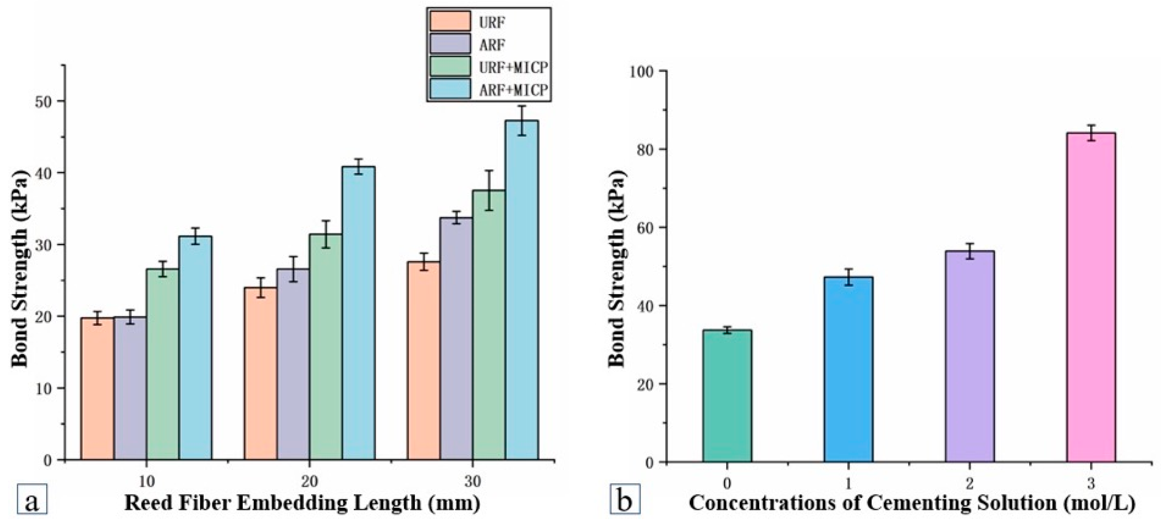
Analysis of the fiber pull-out test results (Figure 14) showed that the bond strength between the reed fibers and sand particles increased with the increase in the embedded length of the reed fibers in the soil. Furthermore, the bond strength between the alkali-treated reed fibers and sand particles was significantly enhanced (Figure 14a). As the deposition of CaCO3 occurs, the three bond strength between the reed fibers and sand particles is significantly improved. When the embedded depth reached 30 mm, the bond strength of the ARF group increased by 22% compared with the URF group, while the bond strength of the ARF + MICP and URF + MICP groups increased by approximately 71% and 36%, respectively.
When the embedded depth of the reed fibers was 30 mm, the bond strength between the reed fibers and sand particles in the ARF group was significantly enhanced with the increase in the concentration of the cementation solution (Figure 14b), reaching 81.141 kPa, which was 2.494 times that of the URF group. In summary, the bond strength between the reed fibers and sand particles was improved to a certain extent after alkali treatment of the reed fibers, and it was significantly enhanced with the increase in the concentration of the cementation solution.

4.4. The Influence of Fiber Parameters on the Mechanical Properties of Cured Soil

4.4.1. Analysis of Microbial Retention Rate

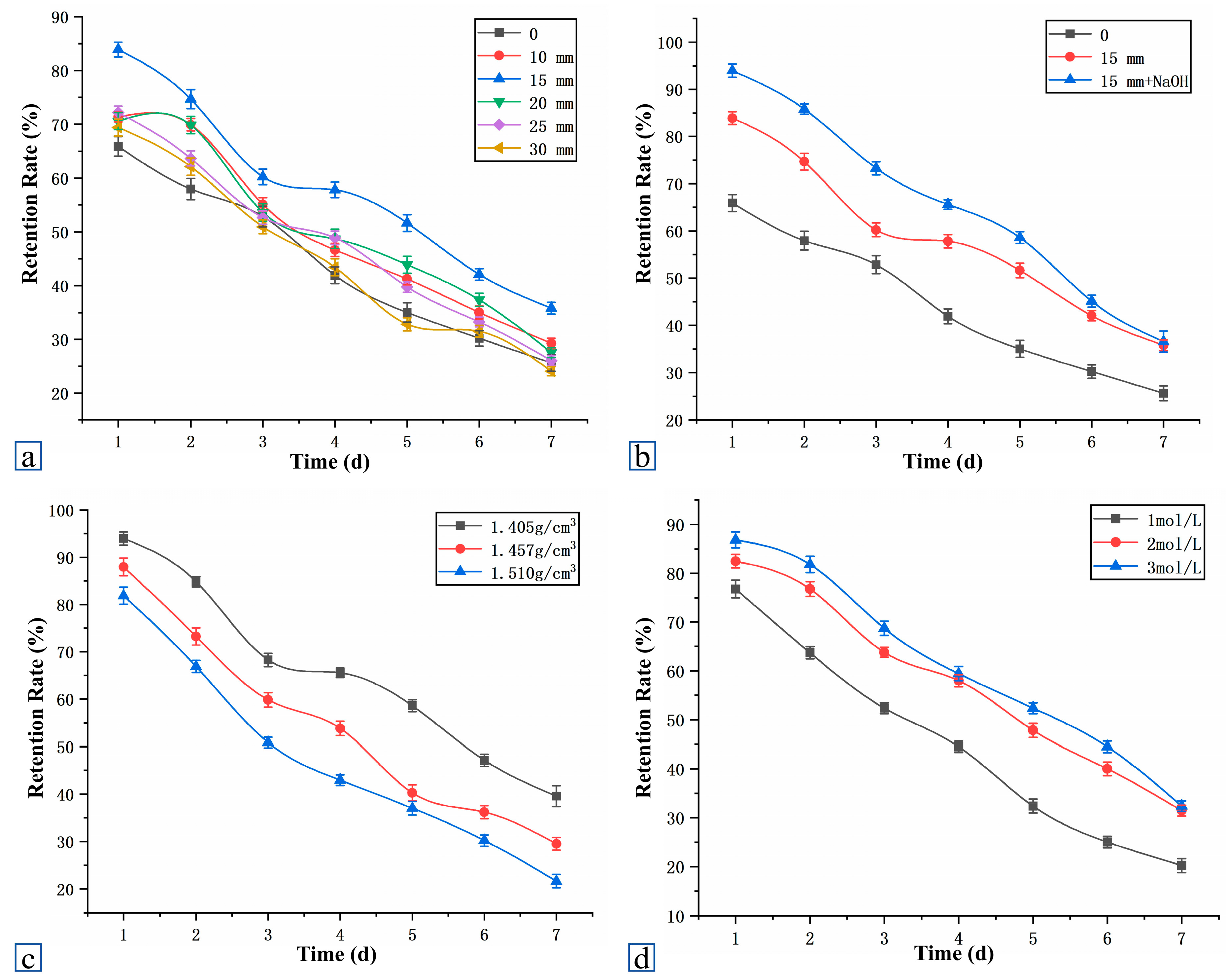
Figure 15 summarizes the effects of different conditions on the retention rate of the strains.
Figure 15a shows that under optimal curing conditions, the strain retention rate increased and then decreased with the increase in fiber length, reaching a peak at 15 mm; thereafter, as the number of grouting times increased, the retention rate decreased due to the generated CaCO3 filling the pores and hindering the strain from penetrating. Figure 15b indicates that the strain retention rate of the ARF group was higher than that of the URF group, suggesting that alkaline treatment enhances the surface roughness of the fibers, increasing the adsorption sites.
Figure 15c shows that when the adhesive solution concentration is constant, an increase in initial dry density reduces the strain retention rate, as the reduced pores limit the strain’s attachment.
Figure 15d shows that under constant dry density conditions, increasing the adhesive solution concentration enhanced the retention rate, but the increase slowed down at 3 mol/L, as the high concentration of adhesive solution promotes rapid CaCO3 generation, which in turn hinders further penetration of the strain and adhesive solution.

4.4.2. Threshold Effects of Fiber Length and Dosage

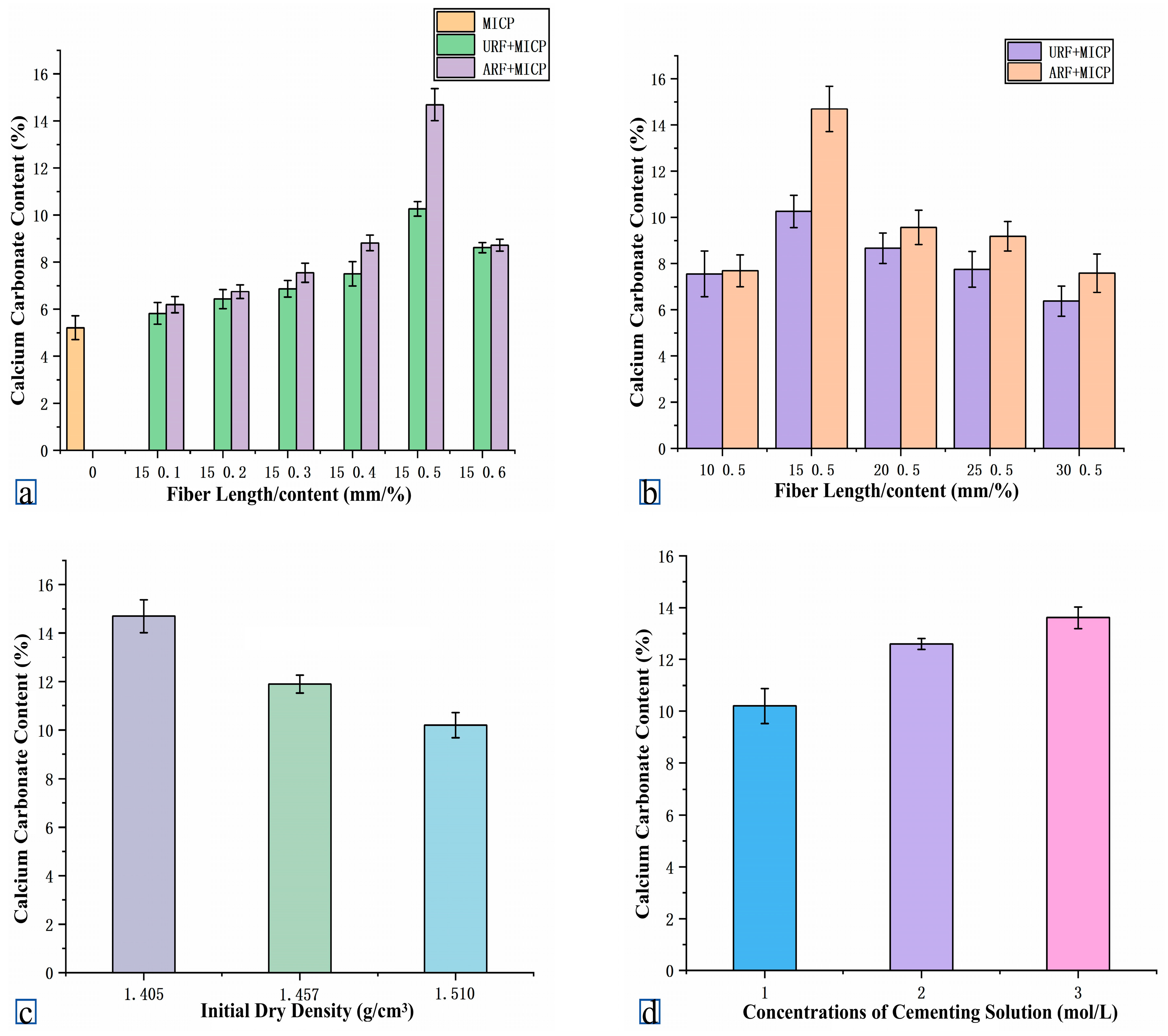
Previous studies have shown that the precipitation trend of CaCO3 during the MICP process is significantly influenced by the fiber length (mm) and dosage (%) [25]. Figure 16 illustrates the effects of the fiber parameters, initial dry density, and grout concentration on CaCO3 generation.
As shown in Figure 16a,b, the calcium precipitation capacity of the strain increased initially and then decreased with the fiber length and dosage, reaching a peak at 15 mm length and 0.5% dosage. Moderate fiber content can increase the strain’s adsorption sites, promoting CaCO3 precipitation; however, excessive fiber tends to aggregate, hindering uniform penetration of the strain and grout, thereby inhibiting precipitation. At this point, the CaCO3 content in the ARF + MICP group was 2.820 times that of the MICP group, significantly outperforming the URF + MICP group (1.970 times), indicating that alkalization enhances fiber adsorption performance. Figure 16c shows that under the optimal fiber parameters, CaCO3 generation decreased gradually with increasing initial dry density. This was due to improved soil compaction reducing pore space, thereby limiting strain and grout infiltration. Figure 16d indicates that increasing grout concentration enhanced CaCO3 generation, but the growth rate slowed after reaching 3 mol/L. While a high calcium source concentration can rapidly promote precipitation, it may also clog pores, restricting subsequent reactant penetration and inhibiting later-stage precipitation.
In summary, the appropriate fiber length and dosage contribute to enhancing microbial retention and CaCO3 precipitation; however, excessively high dry density and grout concentration may lead to pore blockage, limiting the reaction efficiency and reducing the final calcium precipitation effectiveness.

4.4.3. The Effect of Fiber Addition on Sample Strength

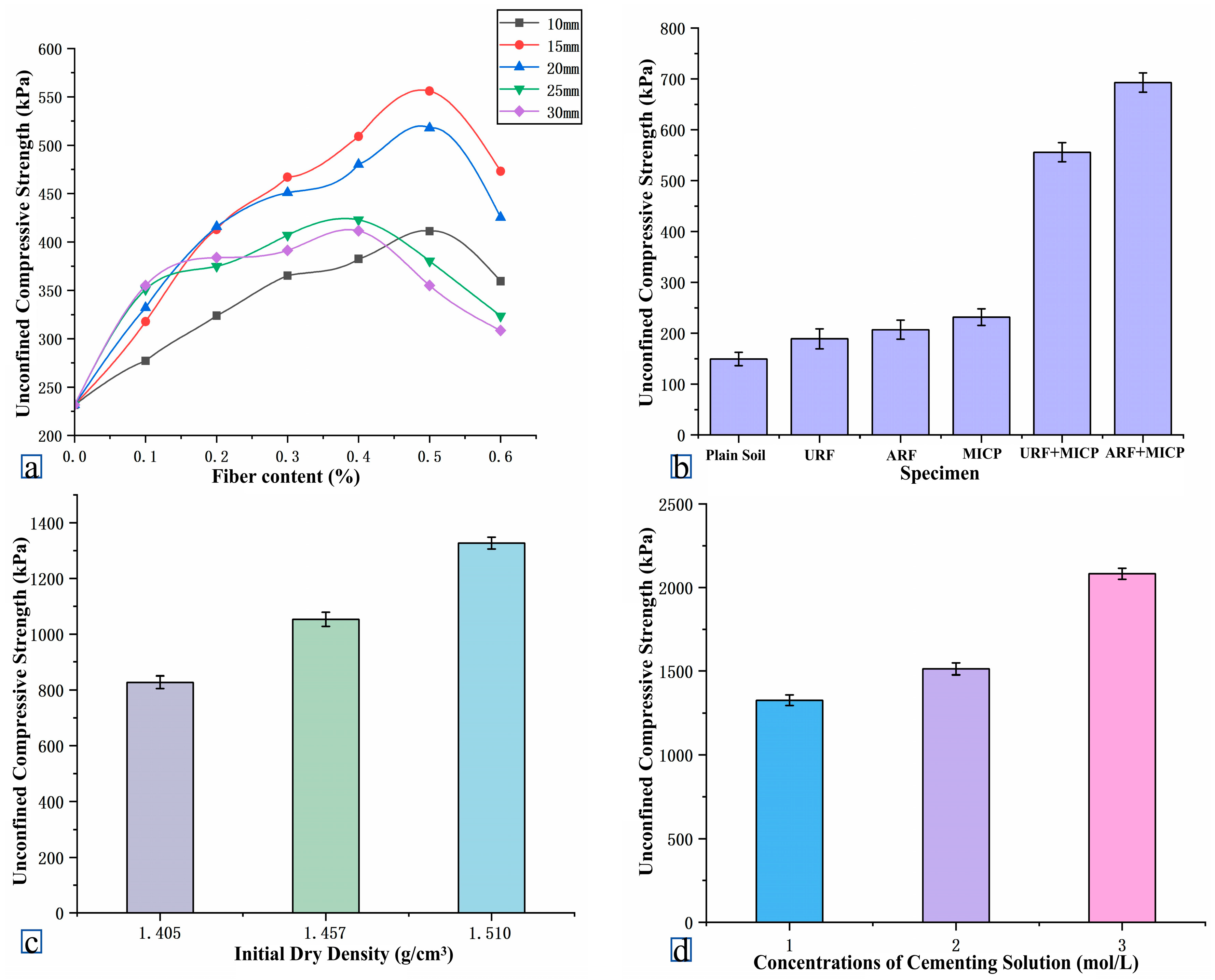
Figure 17a shows the effect of fiber addition on the strength of the sample. The unconfined compressive strength (UCS) test results showed that MICP treatment significantly improved the strength of the sand sample, with a 55.17% increase compared with the plain soil sample. The strength was further enhanced after the addition of fibers. The UCS of the sample first increased and then decreased with the fiber length and dosage. When the length was 15 mm and the dosage 0.5%, the UCS reached a peak of 555.835 kPa. This is because an appropriate amount of fiber promotes the effective precipitation of calcium carbonate, enhancing the curing effect; however, excessive or excessively long fibers can easily aggregate and affect their uniform distribution in the soil, thereby interfering with the interaction between bacterial strains and cementing fluids, leading to the uneven precipitation of calcium carbonate and ultimately weakening the reinforcement effect.
Figure 17b shows that fiber incorporation enhanced the sample strength, with the ARF group strength increasing by 9.57% compared with the URF group. This was due to the alkalization treatment enhancing the fiber surface roughness and improving its bonding with sand particles. After MICP treatment, the sample strength increased by 22.20% and 11.94% compared with the URF and ARF groups, respectively, indicating that while the fibers had a certain strengthening effect, the sand particles still lacked overall bonding.
MICP binds sand particles into a whole through CaCO3 deposition, significantly inhibiting their relative displacement, but also causing brittle failure. The combination of fibers and MICP effectively compensates for this deficiency. CaCO3 deposition enhances fiber–sand particle bonding and improves the fiber pull-out resistance. The “bridge effect” also inhibits crack propagation and improves fracture toughness. The URF + MICP and ARF + MICP groups had an increased strength up to 2.40 and 2.99 times that of the MICP group, respectively, with the ARF + MICP group achieving the highest strength of 692.83 kPa.
Figure 17c focuses on the effect of the initial dry density on sample strength. It shows that as the initial dry density increases, the sample strength rises accordingly. Specifically, although a higher initial dry density reduced the total CaCO3 content in the sample, it enhanced the contact between the fiber and sand particles and increased the effective bonding ratio of the system. This synergistic effect ultimately elevated the sample strength to 1327.18 kPa.
Figure 17d illustrates the influence of the cementing solution concentration on sample strength. It indicates that an increase in the concentration of the cementing solution promoted the deposition of CaCO3 in the sample, which in turn led to a gradual increase in sample strength. When the concentration of the cementing solution reached 3 mol/L, the sample strength reached its peak, with a specific value of 2082.85 kPa.
Therefore, MICP treatment significantly enhances soil strength, while fiber addition further improves tensile and crack resistance. The ARF + MICP combination showed the best effect, demonstrating superior reinforcement performance and toughness.

4.4.4. The Failure Pattern of Unconfined Compressive Strength

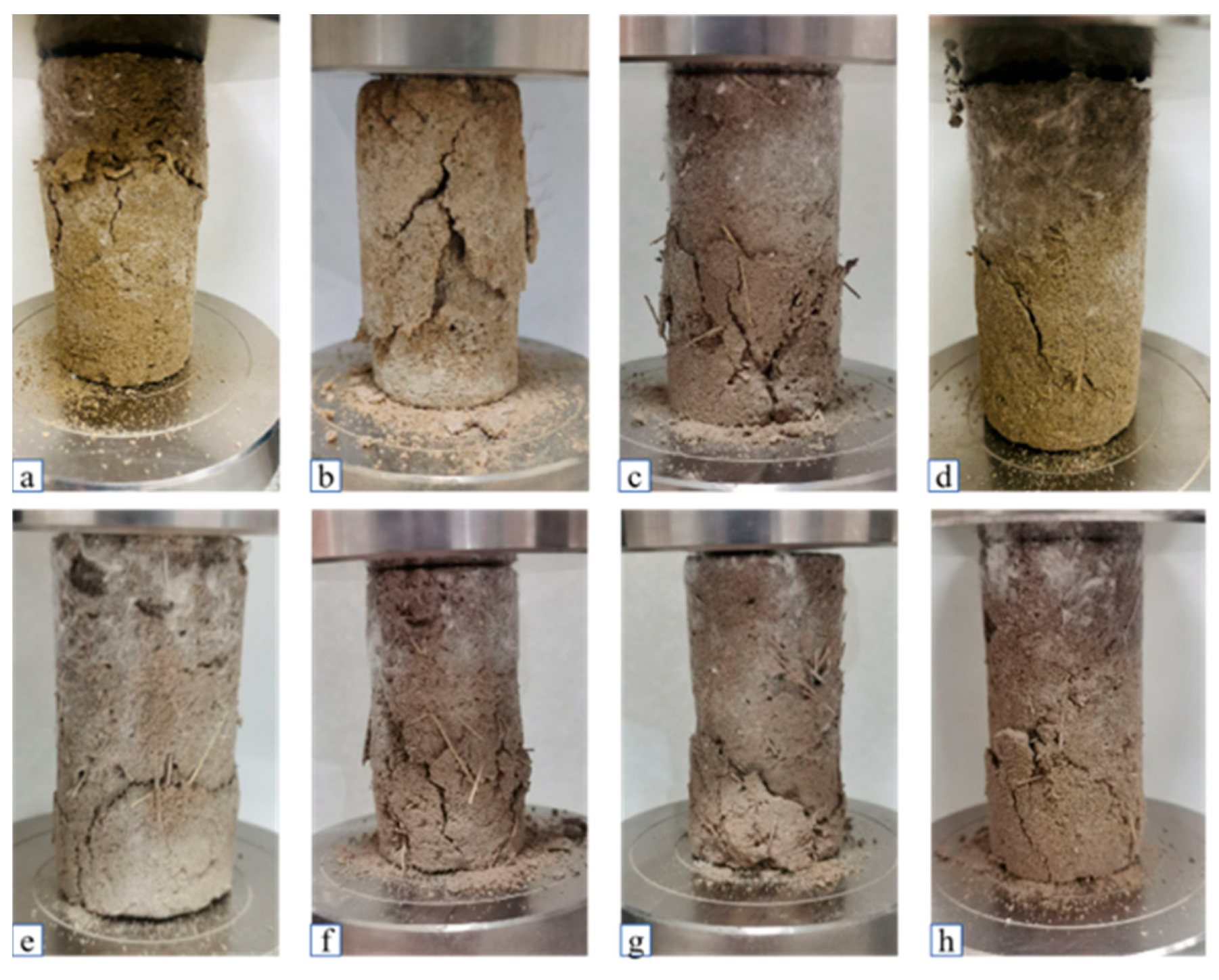
In the samples treated with Phragmites australis fiber-MICP, the addition of Phragmites australis fiber significantly improved the unconfined compressive strength of the samples. Due to the unevenness of the MICP-cured samples, the failure generally started from the bottom. Without fiber, cracks extended upward from the bottom throughout the entire sample (Figure 18b). Figure 18c–h indicates that the interaction between the fibers and sand particles effectively delayed the failure of the samples.
After MICP curing, the failure pattern of the samples was closely related to the length and content of the fibers. When the fiber length exceeded 15 mm and the content exceeded 0.5%, the delaying effect on sample failure decreased as the fiber length and content increased.
The failure mode of unconfined compressive strength in the reed fiber MICP treated samples showed that the addition of reed fibers significantly improved the unconfined compressive strength of the samples. Due to the unevenness of the MICP-cured samples, the failure of the samples generally started from the bottom. In the absence of fibers, cracks extended from the bottom upward throughout the entire specimen (Figure 18b). Figure 18c–h indicates that the interaction between fibers and sand particles effectively delayed the failure of the sample, and the failure mode of the sample after MICP curing was closely related to the length and content of the fibers. When the fiber length exceeded 15 mm and the content exceeded 0.5%, the delay effect on sample damage decreased with the increase in fiber length and content. This is because when the fiber length is too long and the content is too high, it will cause the fibers to be unevenly distributed during the sample preparation process, resulting in the phenomenon of “agglomeration”. Therefore, it is very important to choose the optimal fiber length and dosage to achieve the best effect of solidifying soil.

4.5. Fiber-MICP Reinforced Soil Microstructure Enhancement Mechanism

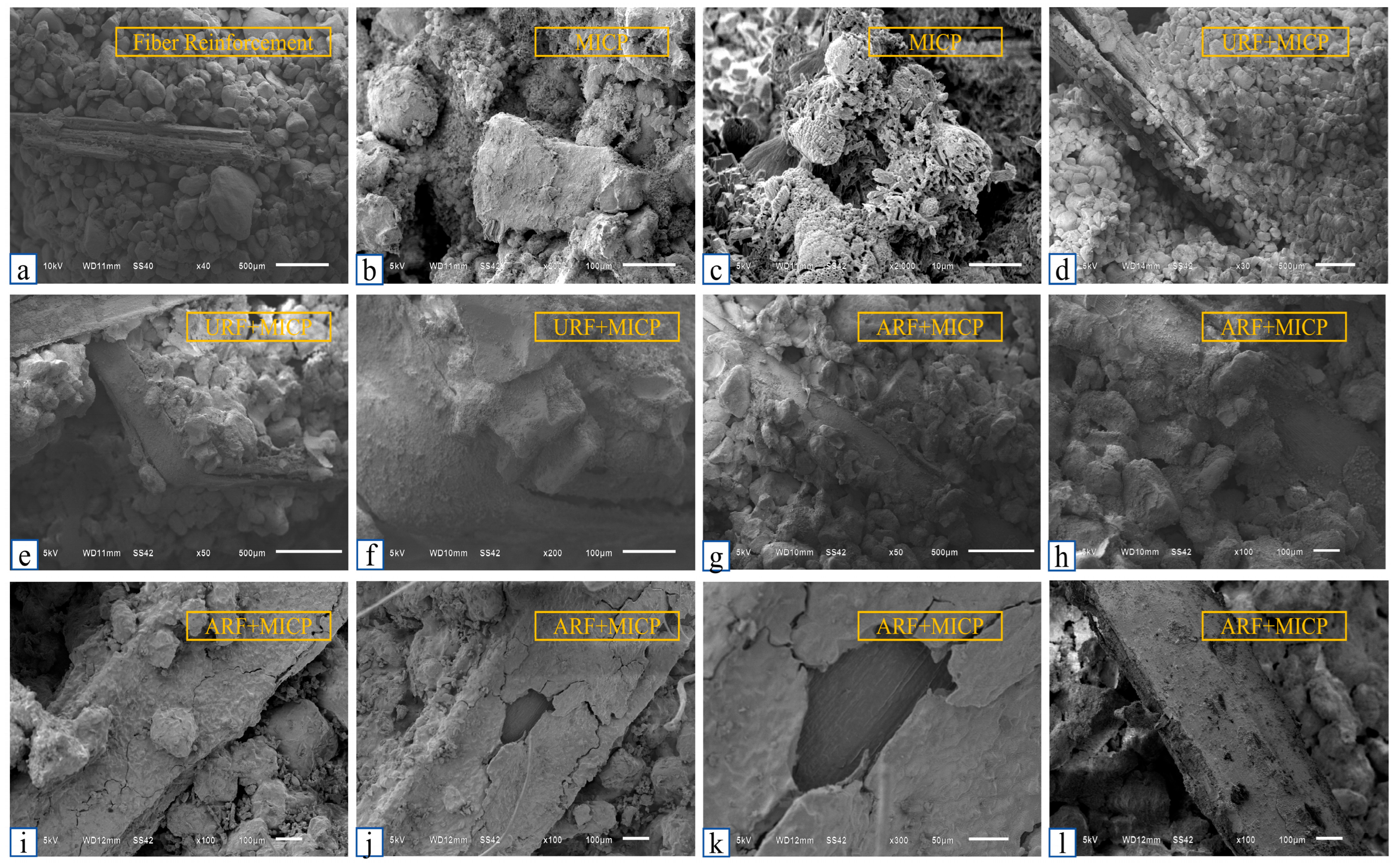
Figure 19 illustrates the microstructural changes in soil strength under the effects of reed fiber, MICP, and their synergistic action.
Figure 19a shows that when reed fibers were added alone, the spaces between the sand particles remained predominantly as pores, with fibers primarily relying on friction to bond with the sand particles, resulting in weak adhesion and limited consolidation effects. Figure 19b,c indicates that after MICP treatment, CaCO3 deposition filled the pores, binding sand particles into a cohesive mass, effectively restricting their relative movement and enhancing the soil strength. However, under ultimate load, the calcium carbonate bonding failed, causing a sudden drop in strength and brittle failure. When fibers were added (Figure 19d–f), they were distributed throughout the sand particles, not only improving the soil toughness, but also providing attachment sites for bacterial strains, promoting their uniform distribution in the soil and enhancing CaCO3 deposition on the fiber surfaces and in pores. After calcium carbonate encases the fibers, the adhesion and pull-out resistance between fibers and sand particles are improved, thereby strengthening the fibers’ constraint on sand particles. In the ARF group (Figure 19i–k), the fiber surfaces were completely covered by calcium carbonate; combined with their high elastic modulus and tensile strength, the specimens exhibited superior compressive and shear resistance. Additionally, the porosity was further reduced due to CaCO3 filling, and the sand particles were more securely bonded. As the content of CaCO3 increased, the solidification effect continued to enhance. However, under load, the calcium carbonate on the fiber surfaces peeled off, and fibers were pulled out as a whole, leading to the failure of reinforcement effects, indicating that the “bridge effect” has an upper limit for improvement.
Figure 20 further reveals the synergistic stabilization mechanism of reed fiber-MICP: appropriate fiber length and dosage facilitate the deposition of CaCO3 in pores and at contact points (Figure 20c), significantly improving the soil structure. Figure 20d shows that the reed fibers and sand particles are organically combined into a whole under the precipitation effect of effectively cemented calcium carbonate, and the spatial network structure formed by the fibers acts as a bridge, thereby enhancing the mechanical anchoring and interlocking effects between the fibers and sand particles, significantly improving the strength and ductility of the soil.

4.6. Comparative Analysis

To contextualize the performance of the alkali-modified reed fiber (ARF)-MICP system for plateau saline soil and highlight its uniqueness relative to existing technologies, Table 4 presents a systematic comparison of the key mechanical properties, critical parameters, and microscopic features between the present study and previously reported microbial-natural fiber soil improvement systems.
As shown in Table 4, the ARF-MICP system proposed in this study demonstrated significantly superior mechanical performance in plateau saline soil compared with the other microbial-natural fiber combinations in the literature: in terms of unconfined compressive strength (UCS), the ARF-MICP treated soil reached 2082.85 kPa—far exceeding the UCS values of jute fiber-MICP treated quartz sand (≈610 kPa, [26]), sisal fiber-EICP treated quartz sand (≈450 kPa, [28]), and lignin fiber-MICP treated seasonal frozen silt (420 kPa after 10 freeze–thaw cycles, [29])—and this remarkable strength enhancement can primarily be attributed to the alkali modification of reed fibers, which optimized the interfacial bonding by yielding a 26.7% higher tensile strength (12.45 N) and a surface roughness (Ra = 1.23 μm) that promoted CaCO3 deposition (85.3% coverage), creating a robust synergistic framework between the fibers, CaCO3, and soil particles. Additionally, the ARF-MICP system outperformed comparative systems in ductility (a critical indicator for mitigating brittle failure in MICP-treated soils): its peak strain of 4.12% was 2.3 times that of the lignin fiber-MICP system (1.8%, [29]) and 2.6 times higher than the peak strain of the unspecified natural fiber-MICP system after 5 wet–dry cycles (1.6%, [30]), and even relative to the jute fiber-MICP system [26]—which lacked quantified peak strain data—its clear ductile failure mode (vs. quasi-ductile failure) confirms the effectiveness of the “fiber bridging-CaCO3 filling” mechanism. Furthermore, the ARF-MICP system achieved these advantages at a low fiber content (0.5%), making it more cost-efficient than the jute fiber-MICP system (3.0% content, [26]) and better suited for large-scale application in cold and arid plateau regions. Notably, Patel et al. [27] improved fine sand’s cohesion and internal friction angle via coir fiber-MICP, but it lacked a quantitative analysis of UCS and ductility, used unmodified fibers, and relied on a “CaCO3 pore-filling” mechanism—distinct from this study’s ARF-modified and “fiber bridging-CaCO3 anchoring” system. Nevertheless, it provides important inspiration for expanding natural fiber source diversity and theoretical support for subsequent research.

5. Conclusions

This study investigated the synergistic solidification of plateau saline soil through alkaline modified reed fiber (ARF) and microbial-induced calcium carbonate precipitation (MICP), revealing the mechanism of fiber microbe synergistic enhancement and optimizing key process parameters. The main conclusions are as follows:
  • Improvement of interface performance: Alkaline modification significantly enhances the interfacial bonding performance between reed fibers and sand particles. The peak tensile strength of the ARF group reached 12.45 N, which was 26.7% higher than that of unmodified fibers (URF). SEM analysis showed that the surface roughness of the modified fibers (Ra = 1.23 μm) and the coverage of calcium carbonate (85.3%) were significantly improved, providing a good interface foundation for synergistic curing.
  • Optimization of mechanical properties: Orthogonal experimental results showed that when the fiber length as 15 mm, the dosage was 0.5%, the dry density was 1.55 g/cm3, and the concentration of the binder was 3.0 mol/L, the unconfined compressive strength (UCS) of the solidified soil reached 2082.85 kPa, which was 2.99 times higher than that of the traditional MICP group. The stress–strain curve showed that the peak strain (ε = 4.12%) of the ARF-MICP group significantly increased, and the failure mode changed from brittle fracture to ductile failure.
  • Based on the experimental results, a collaborative reinforcement model of “fiber bridging calcium carbonate filling” was proposed, revealing the bidirectional reinforcement mechanism of fiber constrained calcium carbonate distribution and calcium carbonate-reinforced fiber anchoring, providing a theoretical basis for the ecological restoration of plateau saline soil. Recommended process parameters include a fiber length of 15 mm, dosage of 0.5%, bonding solution concentration of 3.0 mol/L, and dry density of 1.55 g/cm3. Construction process: layered compaction → bacterial solution injection → bonding and solidification → curing for 7 days. Scope of application: suitable for high-altitude saline soil areas with salt content ≤ 5% and freeze–thaw cycles ≤ 10 times/year.

Author Contributions

Y.D. and Z.B. conceived the idea and carried out the experiments. Y.D. performed the data analysis and wrote the manuscript. X.W. and R.W. provided assistance in the experiment. W.Z. provided guidance. All authors have read and agreed to the published version of the manuscript.

Funding

This work was supported by the National Natural Science Foundation of China (Grant No. 51468055) and the Qinghai Province Key Research and Development Transformation Project (Grant No. 2022-QY-224).

Institutional Review Board Statement

Not applicable.

Informed Consent Statement

Not applicable.

Data Availability Statement

All data analyzed during this study are included in this published article.

Acknowledgments

The authors would like to thank Zhang for his valuable suggestions and field assistance.

Conflicts of Interest

The authors declare no conflict of interest.

References

  1. An, L. Deserts and sandlands in China (Part I). Encycl. Knowl. 2021, 17, 40–41. [Google Scholar]
  2. Ma, M.; Li, X.T.; Tang, C.P. Current situation, causes, and prevention strategies of desertification. Mod. Hortic. 2014, 8, 154–155. [Google Scholar] [CrossRef]
  3. Luo, Y.D. Discussion on characteristics of saline soil and its foundation treatment methods. Miner. Explor. 2019, 10, 1214–1218. [Google Scholar] [CrossRef]
  4. Li, P.F.; Yang, Y.L.; Lan, T.; Guo, S.W.; Zhang, K.; Han, J.W.; Zhang, Q. Soil physicochemical properties and water retention characteristics of improved coastal saline soil in Tianjin. Trans. Chin. Soc. Agric. Eng. 2017, 33, 149–156. [Google Scholar] [CrossRef]
  5. Dejong, J.T.; Soga, K.; Kavazanjian, E.; Burns, S.; van Paassen, L.A.; Al Qabany, A.; Aydilek, A.; Bang, S.S.; Burbank, M.; Caslake, L.F.; et al. Biogeochemical processes and geotechnical applications: Progress, opportunities, and challenges. Géotechnique 2013, 63, 287–301. [Google Scholar] [CrossRef]
  6. Montoya, B.M.; Dejong, J.T. Stress-strain behavior of sands cemented by microbially induced calcite precipitation. J. Geotech. Geoenvironmental Eng. 2015, 141, 04015019. [Google Scholar] [CrossRef]
  7. Liu, L.; Shen, Y.; Liu, H.L.; Chu, J. Application research of microbial cementation in prevention of dam failure. Rock Soil Mech. 2016, 37, 3410–3416. [Google Scholar]
  8. Stocks-Fischer, S.; Galinat, J.K.; Bang, S.S. Microbiological precipitation of CaCO3. Soil Biol. Biochem. 1999, 31, 1563–1571. [Google Scholar] [CrossRef]
  9. Zheng, J.J.; Song, Y.; Lai, H.J.; Cui, M.J.; Wu, C.C. Experimental study on shear strength of microbially induced calcite precipitation (MICP)-treated fiber-reinforced sand. J. Civ. Environ. Eng. 2019, 41, 15–21. [Google Scholar]
  10. Yin, L.Y.; Tang, C.S.; Zhang, L. Mechanical properties of calcareous sand modified by MICP combined with fiber reinforcement. Geol. J. China Univ. 2021, 27, 679–686. [Google Scholar]
  11. Jiang, Z.; Peng, J.; Xu, P.X.; Wei, R.J.; Li, L.L. Experimental study on high strength of calcareous sand reinforced by microbes combined with carbon fiber. J. Civ. Environ. Eng. 2024, 46, 64–73. [Google Scholar]
  12. Li, L.; Zhao, Q.; Zhang, H.; Amini, F.; Li, C. A full contact flexible mold for preparing samples based on microbial-induced calcite precipitation technology. Geotech. Test. J. 2014, 37, 917–921. [Google Scholar] [CrossRef]
  13. Chen, H.J.; Peng, C.F.; Tang, C.W.; Chen, Y.T. Self-healing concrete by biological substrate. Materials 2019, 12, 4099. [Google Scholar] [CrossRef]
  14. Choi, S.-G.; Wang, K.; Chu, J. Properties of biocemented, fiber reinforced sand. Constr. Build. Mater. 2016, 120, 623–629. [Google Scholar] [CrossRef]
  15. Li, W.C.; Jiang, Y.M.; Qi, Y.X. Research overview of reed fiber and its reinforced composites. Knitt. Ind. 2022, 11, 73–76. [Google Scholar]
  16. Lu, J.; Liu, Z.H.; Si, Y.B.; Xu, J.J.; Du, Y.F.; Dong, L. Characteristics, development and utilization, and control methods of reed. Weed Sci. 2007, 3, 7–8,24. [Google Scholar]
  17. GB/T 50123-2019; Standard for Soil Test Methods. China Standards Press: Beijing, China, 2019.
  18. Wang, W.; Sun, C.; Cui, J.D. Adsorption properties of composite modified reed fiber for cationic dyes. Wool Text. J. 2022, 50, 55–61. [Google Scholar]
  19. Fang, X.; Yang, Y.; Chen, Z.; Liu, H.; Xiao, Y.; Shen, C. Influence of fiber content and length on engineering properties of MICP-treated coral sand. Geomicrobiol. J. 2020, 37, 582–594. [Google Scholar] [CrossRef]
  20. Liang, S.; Xiao, X.; Wang, J.; Wang, Y.; Feng, D.; Zhu, C. Influence of fiber type and length on mechanical properties of MICP-treated sand. Materials 2022, 15, 4017. [Google Scholar] [CrossRef]
  21. Zhang, D.; Shahin, M.A.; Yang, Y.; Liu, H.L.; Cheng, L. Effect of microbially induced calcite precipitation treatment on the bonding properties of steel fiber in ultra-high performance concrete. J. Build. Eng. 2022, 50, 10413. [Google Scholar] [CrossRef]
  22. Hou, F.X.; Zhao, Y.; Hu, P.S.; Li, B.; Zhang, W. Screening and identification of new salt-tolerant urease microorganisms in cold and arid regions. J. Arid. Land Resour. Environ. 2021, 35, 178–183. [Google Scholar]
  23. Feng, N.; Guo, X.; Liang, S. Enhanced Cu(II) adsorption by orange peel modified with sodium hydroxide. Trans. Nonferrous Met. Soc. China 2010, 20, s146–s152. [Google Scholar] [CrossRef]
  24. Wang, J.; Liu, M.; Duan, C.; Sun, J.P.; Xu, Y.W. Preparation and characterization of cellulose-based adsorbent and its application in heavy metal ions removal. Carbohydr. Polym. 2019, 206, 837–843. [Google Scholar] [CrossRef]
  25. Gupta, M.K.; Srivastava, R.K.; Bisaria, H. Potential of jute fibre reinforced polymer composites: A review. Int. J. Fiber Text. Res. 2015, 5, 30–38. [Google Scholar]
  26. Imran, M.A.; Gowthaman, S.; Nakashima, K.; Kawasaki, S. The influence of the addition of plant-based natural fibers (jute) on biocemented sand using MICP method. Materials 2020, 13, 4198. [Google Scholar] [CrossRef] [PubMed]
  27. Patel, C.; Patel, R.; Patel, S. Influence of Shear Strength Parameters on Loose Fine Sand Treated with Coir Fiber and Microbially Induced Calcite Precipitation. Springer Proc. Mater. 2022, 2, 68. [Google Scholar] [CrossRef]
  28. Li, J.; Zhang, Y.; Liu, H. Experimental Investigation on Mechanical Behavior of Sands Treated by Enzyme-Induced Calcium Carbonate Precipitation with Assistance of Sisal-Fiber Nucleation. Front. Earth Sci. 2022, 10, 992474. [Google Scholar] [CrossRef]
  29. Li, Q.F.; Xing, Z.G.; Dang, B.; Peng, E.X.; Hu, X.Y. Study on the Mechanical Properties of Lignin Fiber-MICP Solidified Silt under Freezing and Thawing Cycles. J. Glaciol. Geocryol. 2024, 46, 1828–1838. [Google Scholar]
  30. Chen, H.; Li, X.; Zhang, Q. Performance of MICP-Treated Soil against Environmental Deterioration. In GeoHunan International Conference; ASCE: Reston, VA, USA, 2023; pp. 16–23. [Google Scholar] [CrossRef]
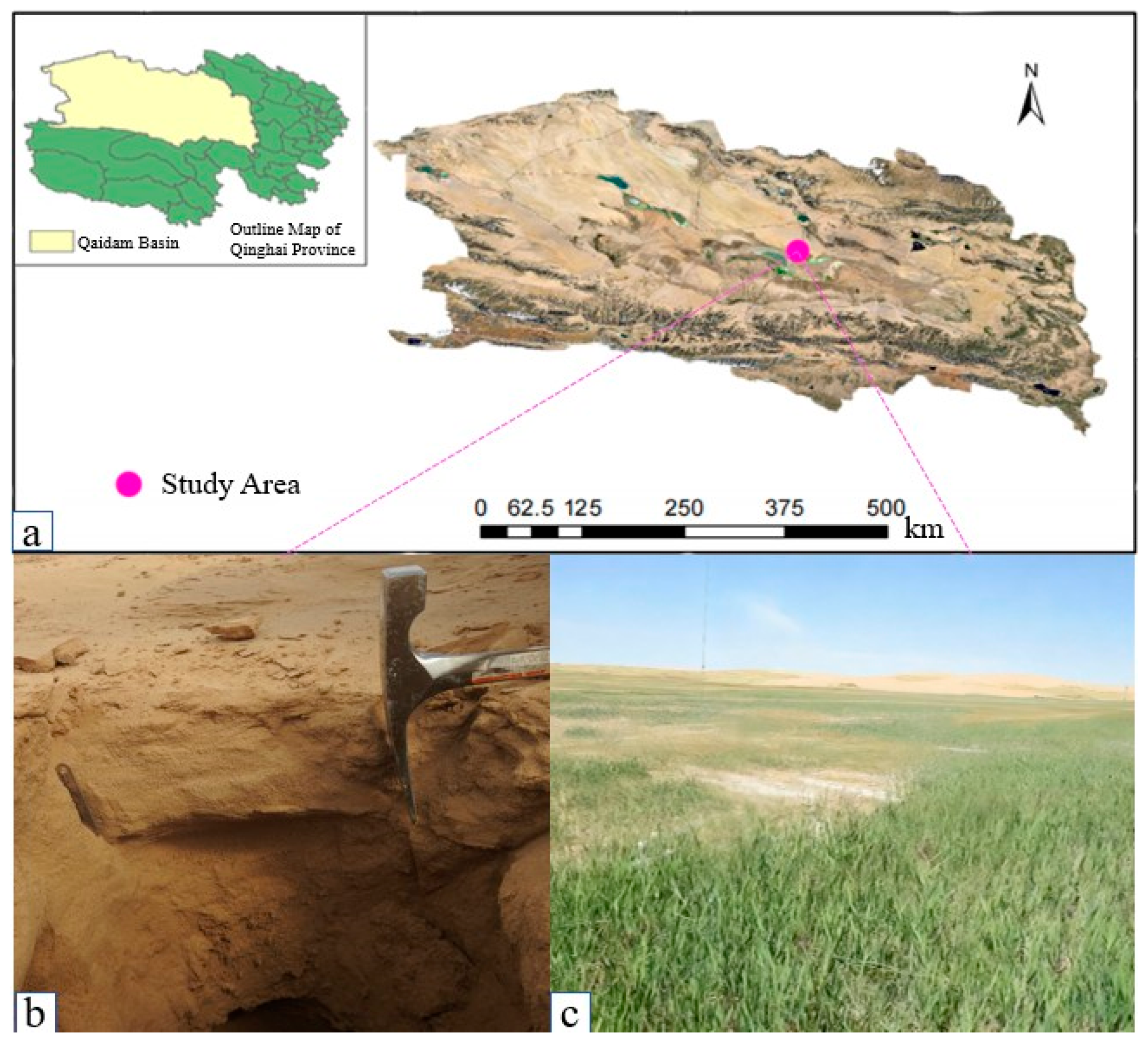
Figure 1. Regional location and sampling points in the study area. (a) Location diagram of the study area; (b) saline soil sampling site; (c) reed specimen collection site.
Applsci 15 11198 g001
Figure 2. Grain size distribution curve of saline sandy soil in the study area.
Applsci 15 11198 g002
Figure 3. Reed fiber: (a) URF; (b) ARF.
Applsci 15 11198 g003
Figure 4. Differences in calcium carbonate precipitation on reed fibers induced by strains under varying cementation solution concentrations.
Applsci 15 11198 g004
Figure 5. Pull-out test of reed fiber: (a) control group; (b) MICP treatment group.
Applsci 15 11198 g005
Figure 6. Strain growth curve.
Applsci 15 11198 g006
Figure 7. Urease activity of three urease-degrading microorganisms under temperature gradient.
Applsci 15 11198 g007
Figure 8. The principle of microbial-induced adsorption precipitation to produce calcium carbonate minerals.
Applsci 15 11198 g008
Figure 9. Comparative SEM micrographs of calcium absorption by different strains on reed fibers (×100): (a) A80; (b) Bp; (c) Sp.
Applsci 15 11198 g009
Figure 10. Surface structure of reed fiber: (a) URF; (b) ARF.
Applsci 15 11198 g010
Figure 11. Microscopic characteristics of mineralization and adsorption of the A80 strain: (a) URF; (b) ARF.
Applsci 15 11198 g011
Figure 12. The amount of calcium adsorbed by strain.
Applsci 15 11198 g012
Figure 13. Microstructure of calcium induced by strain adsorption at different concentrations of cementation solution. URF: (a) 1 mol/L, (b) 2 mol/L, and (c) 3 mol/L. ARF: (d) 1 mol/L, (e) 2 mol/L, and (f) 3 mol/L).
Applsci 15 11198 g013aApplsci 15 11198 g013b
Figure 14. Pull-out test analysis. (a) Effect of reed fiber embedding length on the bond strength. (b) Effect of different cementing solution concentrations on the bond strength of the ARF group.
Applsci 15 11198 g014
Figure 15. Strain retention rate under different conditions: (a) fiber length and grouting times; (b) fiber treatment (URF vs. ARF); (c) initial dry density; (d) cementation solution concentration.
Applsci 15 11198 g015
Figure 16. Comparison of calcium carbonate production under different conditions: (a) fiber length (mm) and content (%), (b) fiber length (mm) and content (%) (URF vs. ARF comparison), (c) initial dry density (g/cm3), and (d) concentrations of cementing solution (mol/L).
Applsci 15 11198 g016
Figure 17. Analysis of compressive strength under different conditions: (a) fiber length (mm) and content (%), (b) specimen type (plain soil, URF, ARF, MICP, URF + MICP, ARF + MICP), (c) initial dry density (g/cm3), and (d) concentrations of cementing solution (mol/L).
Applsci 15 11198 g017
Figure 18. Comparison of the compressive failure modes of specimens. (a) Raw soil sample; (b) MICP; (c) 10 mm (0.5%); (d) 15 mm (0.5%); (e) 20 mm (0.5%); (f) 25 mm (0.5%); (g) 30 mm (0.5%); (h) 15 mm (0.6%).
Applsci 15 11198 g018
Figure 19. Microstructure of the fiber reinforced-MICP solidified saline soil. (a) Microstructure of sand reinforced by single reed fiber (predominant inter-particle pores; fibers bond with sand particles mainly via friction, showing weak adhesion); (b) Microstructure of sand after MICP treatment (CaCO3 deposition begins to fill inter-particle pores); (c) Microstructure of sand after MICP treatment (high-magnification view of CaCO3 deposits binding sand particles into a cohesive mass); (d) Microstructure of sand with URF + MICP (reed fibers distributed among sand particles; fibers act as attachment sites for bacteria, initiating uniform CaCO3 deposition in pores and on fiber surfaces); (e) Microstructure of sand with URF + MICP (fibers distributed throughout sand matrix, facilitating bacterial colonization and CaCO3 accumulation); (f) Microstructure of sand with URF + MICP (CaCO3 encases fibers, improving adhesion and pull-out resistance between fibers and sand particles); (g) Microstructure of sand with ARF + MICP (ARF integrated into sand matrix, CaCO3 effectively bonds sand particles around fibers); (h) Microstructure of sand with ARF + MICP (high-magnification view of ARF-sand particle interaction enhanced by CaCO3 deposition); (i) Microstructure of sand with ARF + MICP (ARF surface completely coated by CaCO3; porosity reduced due to extensive CaCO3 filling, sand particles bonded more securely); (j) Microstructure of sand with ARF + MICP (ARF surface fully covered by CaCO3, promoting strong interfacial bonding with sand particles); (k) Microstructure of sand with ARF + MICP (under load: CaCO3 peels off from ARF surface, initiating fiber pull-out); (l) Microstructure of sand with ARF + MICP (under load: overall pull-out of ARF fibers (with CaCO3 detachment), leading to failure of reinforcement effect).
Applsci 15 11198 g019
Figure 20. Schematic diagram of reed fiber-MICP solidified soil.
Applsci 15 11198 g020
Table 1. Types and contents of soluble salts in chloride saline silty sand.
Sampling Depth (m)pHTypes of Easily Soluble Salts (g/kg)Total Salt Content (g/kg)Types of Saline Soil
CO32−HCO3ClSO42−K+Na+Ca2+Mg2+
0.08.1500.4612.431.801.920.811.732.4639.60Chloride Saline Soil
Table 2. Physical properties of the reed fiber.
NameColorLength (mm)Thickness (mm)Tensile Strength (MPa)Moisture Content (%)Cross-Sectional Shape
Reed FiberLight Yellow600.19~0.21610.133.6%Rectangular
Table 3. TSA culture medium.
TSA Medium ComponentsDosage/(g·L−1)
Tryptone17 g
Soy peptone3 g
NaCl5 g
K2PHO42.5 g
Glucose2.5 g
Table 4. Comparison of the key mechanical properties and parameters for microbial-natural fiber synergistic soil improvement.
Source of StudySoil Type ImprovedFiber Type and Modification MethodKey Parameters (Fiber/Curing System)Core Mechanical Property IndicatorsInterface and Microscopic CharacteristicsFailure Mode
Present StudyPlateau saline soilAlkali-modified reed fiber (ARF)Length: 15 mm, content: 0.5%; cementing solution: 3.0 mol/L, dry density: 1.55 g/cm3Unconfined compressive strength (UCS) = 2082.85 kPa, 2.99 times higher than conventional MICP group; peak strain = 4.12%Fiber tensile strength = 12.45 N (26.7% higher than unmodified reed fiber (URF)); surface roughness Ra = 1.23 μm; CaCO3 coverage rate = 85.3%Ductile failure
Imran, A.; Gowthaman, S.; Nakashima, K.; Kawasaki, S. (2020) [26]Quartz sandUnmodified jute fiberLength: 15 mm, content: 3.0%; cementing solution concentration not specifiedOptimal UCS ≈ 610 kPa, approximately 2.0 times higher than pure MICP group; peak strain not reportedFibers provide attachment sites for CaCO3 precipitation, reducing specimen brittlenessQuasi-ductile failure
Patel, C.; Patel, R.; Patel, S. (2022) [27]Fine sandUnmodified coir fiberAspect ratio: 182, content: 0.3%; cementing solution: 3.0 mol/LCohesion increased by 6 times compared with pure MICP group; internal friction angle = 42° (1.4 times higher than pure MICP group); UCS not measuredCaCO3 fills pores, and fibers enhance inter-particle constraintBrittleness reduction
Patel, C.; Patel, R.; Patel, S. (2022) [28]Quartz sandUnmodified sisal fiberLength: 10 mm, content: 0.2%; enzyme-induced calcium carbonate precipitation (EICP) curing systemOptimal UCS ≈ 450 kPa, 4.0 times higher than pure EICP group; peak strain data fluctuated and was not quantifiedFibers provide nucleation sites on their surface, forming a “bridging network”; CaCO3 crystals are interwovenEnhanced ductile characteristics
Li, Q.F.; Xing, Z.G.; Dang, B.; (2024) [29]Silt in seasonal frozen regionsUnmodified lignin fiberContent: 1.5%; cementing solution concentration not specified, dry density not specifiedUCS = 420 kPa (after 10 freeze–thaw cycles), 17.5% higher retention rate than pure MICP group; peak strain = 1.8%CaCO3 content was 426.6% higher than pure MICP group; a dense cemented structure formed among fibers, CaCO3, and soil particlesSemi-brittle failure
Chen, H.; Li, X.; Zhang, Q. (2023) [30]SandUnmodified natural fiberContent not specified; cementing solution concentration not specifiedPeak strain = 1.6% after 5 wet–dry cycles (300% higher than non-fiber group); UCS retention rate = 65%Fibers inhibited the spalling of CaCO3 crystals and reduced the increase in porosityDuctile failure
Disclaimer/Publisher’s Note: The statements, opinions and data contained in all publications are solely those of the individual author(s) and contributor(s) and not of MDPI and/or the editor(s). MDPI and/or the editor(s) disclaim responsibility for any injury to people or property resulting from any ideas, methods, instructions or products referred to in the content.