Abstract
Supercritical carbon dioxide (SC-CO2) jetting has emerged as a promising technique for rock fracturing due to its superior physical properties such as low viscosity, high diffusivity, and zero surface tension. However, the complex interaction mechanisms between SC-CO2 jets and heterogeneous rock media remain inadequately understood. In this study, a coupled Smooth Particle Hydrodynamics–Finite Element Method (SPH-FEM) framework is established to simulate the dynamic fracturing process of rocks under SC-CO2 jet impact. The Riedel–Hiermaier–Thoma (RHT) constitutive model is incorporated to describe the nonlinear damage evolution of brittle rocks, and key material parameters are calibrated via sensitivity analysis and SHPB experimental validation. A series of numerical simulations are performed to investigate the effects of jet standoff distance, jet velocity, and rock lithology (marble, granite, red sandstone) on fracturing efficiency. Damage area, damage volume, and a novel metric—block size distribution—are employed to quantify the fracturing quality from both macro and meso scales. The results indicate that SC-CO2 jets outperform conventional water jets in creating more extensive and homogeneous fracture networks. An optimal standoff distance of 1–2 cm and a velocity threshold of 0.2 cm/μs are identified for maximum fracturing efficiency in marble. Furthermore, smaller block sizes are achieved under higher velocities, indicating a more complete and efficient rock fragmentation process. This study provides a comprehensive numerical insight into SC-CO2 jet-induced rock failure and offers theoretical guidance for optimizing green and water-free rock fracturing techniques in complex geological environments.
1. Introduction
With the continuous growth of global energy demand and the advancement of unconventional resource exploitation, rock fracturing technologies have become increasingly important in fields such as oil and gas extraction, mineral resource development, and underground engineering [1,2,3,4,5]. Currently, the most widely used rock-breaking techniques are hydraulic fracturing and blasting. Hydraulic fracturing enhances hydrocarbon recovery by injecting high-pressure fluid into subsurface reservoirs to initiate and propagate fractures [6]. However, this technique is heavily dependent on water resources, which severely limits its application in arid or water-scarce regions [7]. Furthermore, the chemical additives commonly used in fracturing fluids pose risks of groundwater contamination and ecological damage. In clay-rich formations, hydraulic fracturing may also cause reservoir damage, such as pore clogging and clay swelling, which ultimately reduce permeability and production efficiency [8].
Blasting, another conventional method, exhibits relatively high energy efficiency in fracturing hard rock masses [9,10]. Nonetheless, it suffers from drawbacks such as intense ground vibrations, which may endanger nearby infrastructure and workers, and uncontrolled fracture propagation that can result in excessive rock damage or incomplete fracture networks [11]. Additional safety hazards, including flyrock and toxic gas emissions, further constrain its applicability in underground operations. These limitations highlight the urgent need for a safer, more efficient, environmentally friendly, and broadly applicable rock fracturing technology [12].
In recent years, alternative jet-based methods such as nitrogen jets and liquid CO2 phase-change jets have been proposed to address these challenges [13]. However, nitrogen jets suffer from low density and pressure, leading to inadequate fracturing performance in dense formations [14]. Although liquid CO2 phase-change jets can release high pressure through phase transition to induce rock failure, their complex control requirements and high operational costs hinder widespread application [15]. Against this backdrop, supercritical carbon dioxide (SC-CO2) jets have emerged as a promising green rock-breaking technology due to their unique thermophysical properties [16,17].
SC-CO2 is a fluid above its critical temperature (31.1 °C) and pressure (7.38 MPa), characterized by high density, low viscosity, high diffusivity, and zero surface tension [18]. Unlike hydraulic fracturing, SC-CO2 does not introduce water into the reservoir, thus avoiding water-sensitive swelling and preventing residual fluid contamination. Its gas-like diffusivity enables deep penetration into microfractures, facilitating the formation of complex and interconnected fracture networks, which significantly enhances reservoir permeability and resource recovery [19,20,21]. SC-CO2 jet technology has shown remarkable promise for a wide range of subsurface engineering applications, including geothermal resource development, stimulation of shale gas reservoirs, and enhancement of coalbed methane recovery.
Despite its promise, the underlying mechanisms of SC-CO2 jet-induced rock fracturing remain insufficiently understood. The process involves highly nonlinear fluid–solid interactions, multi-scale crack propagation, and dynamic phase behavior [22,23,24]. Existing studies primarily focus on macroscopic fracture morphology under varying jet parameters, while challenges remain in multi-field coupling modeling, representation of non-Newtonian fluid characteristics, and nonlinear damage evolution of rock materials [25]. Moreover, current evaluations rely mainly on macroscopic indicators such as damage area or volume, but lack mesoscopic-level analyses of fracture products—particularly block size distribution—which are essential for understanding fragmentation efficiency, crack uniformity, and implications for post-fracture operations.
In response to these gaps, this study establishes a coupled SPH-FEM numerical model to simulate the rock fracturing process under SC-CO2 jet impact. The Riedel–Hiermaier–Thoma (RHT) constitutive model is employed to describe the dynamic failure behavior of brittle rocks. By incorporating both damage volume and block size distribution as multi-scale evaluation metrics, this research provides quantitative insights into SC-CO2 jet-induced fracturing and offers theoretical guidance for optimizing environmentally sustainable and water-free fracturing technologies.
2. Methodology
2.1. SPH-FEM Coupling
To accurately capture the complex dynamic response of rocks under high-velocity SC-CO2 jet impact, a coupled Smooth Particle Hydrodynamics–Finite Element Method (SPH-FEM) framework is employed Figure 1. The SPH method is particularly suitable for modeling large deformations, free surface flows, and fluid fragmentation without mesh entanglement issues. It enables robust tracking of jet propagation and fluid-solid interaction in the near-nozzle zone [26]. In contrast, the Finite Element Method (FEM) offers high accuracy and clear stress–strain response modeling in solid materials, making it ideal for representing the mechanical behavior of bulk rock domains. In this study, the SC-CO2 jet region is modeled using SPH particles, while the surrounding rock specimen is discretized with FEM solid elements. A contact-based coupling algorithm is adopted to ensure dynamic equilibrium and information exchange at the SPH–FEM interface.
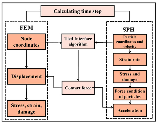
Figure 1.
The process of SPH-FEM coupling.
The calculation process of the SPH-FEM coupling algorithm begins by determining the node coordinates and displacement values, which provide the necessary data for tracking the movement of both the rock and SC-CO2 fluid particles. Next, a contact-based coupling algorithm is used to couple the SPH particles with the FEM nodes, enabling dynamic interaction and information exchange between the fluid and solid domains. This is particularly crucial in high-velocity impact scenarios, ensuring accurate fluid-solid coupling. The coordinates and velocities of the particles are then updated to properly track the movement of the SC-CO2 jet and its interaction with the rock surface. Subsequently, strain rate, stress, and damage are calculated to understand the deformation and failure of the rock material under impact. Finally, the force conditions of the particles are assessed, which affect their acceleration and, consequently, the movement of the rock. This ensures that momentum transfer between the fluid and solid is correctly modeled. By integrating the FEM and SPH methods, the contact-based coupling algorithm ensures that the fluid (SC-CO2) and solid (rock) domains remain dynamically balanced throughout the simulation, especially in high-speed impact scenarios.
2.2. Particle Jet Rock-Fracturing Model
In this study, a hybrid numerical algorithm was employed to construct a particle jet rock-fracturing model. The explicit dynamic method was applied to numerically simulate the rock-breaking processes induced by both water jets and SC-CO2 jets. By controlling the interaction time between SC-CO2 particles and the rock, as well as varying the jet standoff distance and velocity parameters, the fracturing mechanism was analyzed in depth. The finite element model of the rock, as shown in Figure 2, uses a cylindrical geometry with a diameter of 20 cm and a height of 40 cm, discretized into approximately 1.4 million mesh elements, providing a high level of detail for simulating the rock’s mechanical behavior under SC-CO2 jet impact. The coupling region was refined with denser meshing, while the jet model was developed using the Smoothed Particle Hydrodynamics (SPH) method and simplified into a circular incident surface with a radius of 0.5 cm. In addition, the time step is set to 1 × 10⁻³ s, which is determined based on the stability criterion to ensure the convergence of numerical calculation.
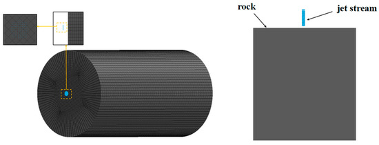
Figure 2.
The Rock Model and Corresponding Mesh Structure.
In the boundary condition settings of the numerical simulation, a non-reflective boundary layer was applied to the lateral and bottom boundaries of the rock model in order to eliminate stress wave reflections at the boundaries, thereby avoiding numerical interference in the evolution of rock damage. To reduce computational complexity, several reasonable simplifications were made for the particle jet impact process: the particle flow field was assumed to be uniformly distributed, and the collision coupling effects between discrete particles were neglected; the rock medium in its initial state was considered as an ideal intact material without pre-existing fractures or defects, and the influence of in situ confining pressure on the damage evolution process was ignored. To further reveal the interaction mechanism between SC-CO2 jets and rock, multiple numerical simulations under different working conditions were conducted, with the specific experimental schemes detailed in Table 1.

Table 1.
SPH Model Parameter Variables.
2.3. Mechanical Constitutive Model
2.3.1. Rock Constitutive Model
The RHT constitutive model is suitable for multi-failure surface coupling processes, allowing for a more detailed description of the progressive damage behavior of brittle materials under complex loading conditions [27,28,29]. It is particularly appropriate for application in numerical simulations of high-velocity jet-induced rock fracturing. In this study, the RHT constitutive model for rock, denoted as MAT_RHT, was adopted for the simulations.
The RHT constitutive model consists of three stages—elastic, linear hardening, and damage softening—and is used to describe the evolution characteristics of brittle materials under complex loading conditions. In the elastic stage, the material follows Hooke’s law, exhibiting a linear stress–strain relationship. In the linear hardening stage, stress gradually increases with the accumulation of plastic strain, which can be represented by a constitutive hardening equation. In the damage softening stage, the material progressively deteriorates, and stress decreases with the evolution of the damage variable until final failure occurs. Overall, the model couples the equation of state, strength criteria, and damage evolution equations to characterize the complete material behavior from initial loading to final failure. The following chapters will analyze the key equations of the three stages in detail, among which Tables S1–S6 (Supplementary Materials) list the specific parameters of the RHT constitutive model.
- (1)
- Failure Surface Equation
The equivalent stress strength on the failure surface is defined as a function of pressure , Lode angle , and strain rate :
where is uniaxial compressive strength; is failure surface parameter; ; is failure surface exponent; is normalized pressure; is the dynamic strain-rate enhancement factor, which provides a corresponding dynamic amplification coefficient for the static failure surface:
where is compressive strain-rate exponent; is tensile strain-rate exponent.
In the RHT model, the Lode angle factor reflects the directional dependence of the deviatoric stress tensor:
where is the ratio of the extension and compression meridians, , , B is the load angle correlation coefficient, , J2 and J3 are the second and third invariants of the strain tensor, and is the strain tensor.
- (2)
- Elastic Limit Surface Equation
The elastic limit surface is determined by the failure surface:
where is the elastic strength-to-failure surface strength ratio which is determined by two input parameters: tensile elastic strength and compressive elastic strength . The cap function at the elastic limit surface restricts elastic stresses under hydrostatic pressure, which reduces the contribution of elastic deformation to material damage while mitigating volume expansion caused by plastic flow during shear.
where = is the pressure at which the material’s pores begin to crush, preventing the material from remaining elastic under high pressure.
- (3)
- Linear Hardening Stage
The RHT model incorporates a mathematical description of the linear hardening stage to effectively characterize the strain hardening behavior of brittle materials. When the equivalent stress in rock does not reach the hardening limit, the system exhibits a typical elastic response. Once the stress exceeds this threshold, the material enters an elastoplastic deformation stage accompanied by the continuous accumulation of plastic strain. During this stage, the yield stress increases proportionally with the accumulated plastic strain according to the linear hardening model, demonstrating a linear evolution of the stress–strain relationship.
During hardening, the current yield surface is determined based on the elastic limit surface and the failure surface:
where G is the shear modulus. From Equations (10) and (20), we can obtain the following:
where is accumulated equivalent plastic strain for the linear strengthening stage, and is the shear modulus reduction coefficient.
- (4)
- Damage Softening Stage
Starting from the hardening stage, additional plastic strain leads to material damage and strength degradation. The damage is accumulated according to the following expression:
where is the equivalent plastic strain increment, , and are the damage constants, is the minimum loss strain, and the failure surface after damage is as follows:
The shear modulus after damage is given by the following:
where is the residual shear modulus.
The calculation formulas for the compressive strain-rate exponent and the tensile strain-rate exponent in the RHT constitutive equations are as follows:
The shear modulus can be calculated based on elastic wave theory:
2.3.2. SC-CO2 Model
The physical parameters of SC-CO2, such as density and dynamic viscosity, can be represented by the MAT_NULL material model. In addition, for the dynamic solution process, volume deformation must be described by the state equation. SC-CO2 can be described by a linear polynomial state equation considering internal energy [30,31,32,33]:
where , , and represent density, initial density and energy per unit volume, respectively; , , , , , and are constant parameters of the medium, ; adiabatic index , and respectively, represent specific heat capacity under constant pressure and specific heat capacity under constant volume.
SC-CO2 is a dense gas with molecular kinetic energy. Under high pressure, the molecular spacing of SC-CO2 is very small. Therefore, the internal energy of SC-CO2 consists of potential energy and kinetic energy. 1 mol SC-CO2 can be obtained by the following formula:
where represents the molecular kinetic energy affected by temperature, which is calculated similarly to that of an ideal gas, and represents the molecular potential energy.
where represents the number of molecules, = 6.0221023 is the Avogadro constant; , , and respectively, represent the mass, molar mass, gas constant and Boltzmann constant, and = 6 is the degree of freedom of CO2.
SC-CO2 can be modeled as a van der Waals gas to calculate its molecular potential energy. When the medium undergoes expansion, this gas must resist both external forces and internal intermolecular interactions. For 1 mol van der Waals gas, the combined molecular attraction on either side of the cross-section is , and the applied force can be expressed as follows:
Therefore, the increase in potential energy can be obtained by the following formula:
The integral above is obtained as follows:
where is the gravitational parameter between carbon dioxide gas molecules; represents the molar volume of carbon dioxide; is the integral constant, for a thin medium, when its volume is infinite, = 0. can be expressed as follows:
The energy per unit volume of SC-CO2 can be calculated by Formulas (22), (23) and (28), and the parameters of CO2 material are shown in Table 2.

Table 2.
CO2 Material Reference.
3. Numerical Analysis of Rock Fracture by SC-CO2 Jet
3.1. Effect of Jet Standoff Distance on Rock-Fracturing Performance
To analyze the effect of standoff distance on rock fracturing, this study conducts jet impact simulations on marble using two media: SC-CO2 and water. The simulations adopt the failure element area and volume as evaluation indices for fracturing performance. The failure element area serves as a key indicator to assess the degree of rock fracture and the failure mode, as it quantifies the regions where stress and strain exceed the material failure criteria, effectively describing the fracturing process under loading or impact [34]. The failure element volume provides information about the extent of damage within the model under specific loading conditions, thereby helping to elucidate the fracture mechanism and evaluate impact resistance [35,36].
By setting the particle jet velocity to 0.2 cm/μs and the jet duration to 150 μs, the fracturing behavior under standoff distances ranging from 0.5 to 3 cm was analyzed. As shown in Figure 3, the variation curves of standoff distance with time indicate that, for water particles, both the failure element area and volume gradually increase over time. However, the increments are relatively small, and as the standoff distance increases, the fracturing effect of water particles on the rock does not show significant improvement. This clearly demonstrates the relatively low efficiency of water particles in rock fracturing. In contrast, SC-CO2 particles, owing to their unique physical properties such as high diffusivity, low density, and compressibility, are able to more effectively damage the rock structure during high-velocity impact. Consequently, the failure element area and volume exhibit more favorable growth trends, with SC-CO2 particles producing a much larger damaged region. The results indicate that SC-CO2 particles have a superior impact fracturing effect on rock compared with water particles.
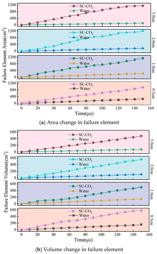
Figure 3.
Effect of penetration distance on crushing degree.
As shown in Figure 4, the failure element area of SC-CO2 particles increases initially and then decreases with the standoff distance. This behavior can be explained by the fact that, at very short distances, diffusion is insufficient, resulting in limited damage. Within the range of 1–2 cm, however, diffusion becomes more effective, leading to a significant increase in failure area and an improvement in fracture volume. Beyond this range, both the damaged area and volume decrease due to constraints imposed by jet radius and diffusion limits.
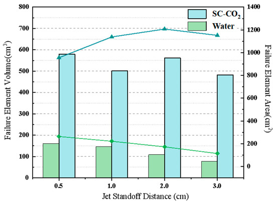
Figure 4.
Volume and area changes in rock failure unit.
In contrast, water particles exhibit weaker fracturing performance because their high viscosity and low diffusivity hinder efficient energy transfer into the rock. As the standoff distance increases, both the failure area and volume caused by water particles decrease further.
Overall, SC-CO2 particles, owing to their high diffusivity, low viscosity, and superior energy transfer capacity, maintain strong fracturing effectiveness even at larger standoff distances, with an optimal range around 1–2 cm. These characteristics highlight the great potential of SC-CO2 jets in rock-breaking applications where extensive damage and efficient energy delivery are required.
3.2. Effect of Jet Velocity on Rock-Fracturing Performance
Jet velocity and standoff distance are the core control parameters that jointly determine the magnitude of kinetic energy input, thereby influencing crack initiation and propagation rates. To reveal the differences in fracturing mechanisms of various rock types, the SC-CO2 jet velocity was set in the range of 0.05–0.3 cm/μs, with the standoff distance fixed at 1 cm and the jet duration at 150 μs, the corresponding actual rock block size is generally less than 800 mm, in order to investigate the effect of jet velocity on rock-fracturing performance.
As shown in Figure 5, when the jet velocity is relatively low, the failure element volume of marble exhibits a gradual and noticeable increase, with the growth curve rising rapidly, indicating that the material strength and deformation capacity of marble have already been significantly degraded under such conditions. As the velocity further increases, the failure volume of marble shows an almost linear growth trend. Overall, marble demonstrates a substantial increase in failure volume even at low impact velocities, suggesting that it is more susceptible to damage; at higher velocities, the growth in failure volume becomes particularly pronounced, revealing a distinct brittle fracture behavior.

Figure 5.
Volume of rock failure unit.
4. Damage Evolution and Mechanism of SC-CO2 Jet-Induced Rock Fracturing
4.1. Rock Chronology Damage Cloud Map Analysis
To further investigate the damage evolution and stress variation in rock failure induced by SC-CO2 jets, this section analyzes the impact simulation results on red sandstone with an incident velocity of 0.2 cm/μs, a standoff distance of 1 cm, and a jet duration of 150 μs. The sequential damage cloud maps and sectional views are shown in Figure 6.
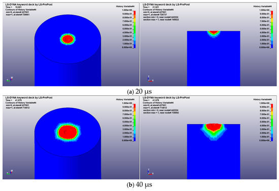
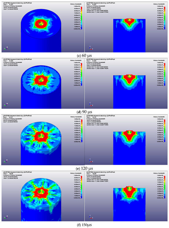
Figure 6.
Red sandstone damage change cloud map and section.
As observed in Figure 6, when high-velocity particles strike the rock surface, the initial damage concentrates in the central area of the top surface, exhibiting pronounced stress concentration. The sectional view indicates that this region has already experienced initial damage but has not yet propagated into deeper layers, while the 3D view highlights the symmetric characteristics of the damage distribution.
With continued loading, particularly after 60 μs, the damage zone progressively expands radially and longitudinally from the center. The extent of the highly damaged region increases markedly, and the appearance of yellow and green areas in the surrounding region indicates that stress has been transmitted to a broader volume. The sectional view further reveals that cracks radiate outward from the center and gradually penetrate into deeper rock layers, ultimately forming a typical funnel-shaped failure pattern.
In the later stage (approximately after 120 μs), the severely damaged region at the top nearly spans the entire surface and continues to propagate downward, resulting in throughgoing failure. The extent of the highly damaged central zone reaches its maximum, while the radial cracks gradually stabilize. The sectional view further confirms the symmetric distribution of cracks and their radial extension, with the upper part of the rock nearly completely destroyed.
In summary, the fracturing process of red sandstone under SC-CO2 jet impact can be described as stress concentration initiating local damage, followed by the radial expansion of cracks accompanied by progressive damage accumulation, and ultimately leading to the formation of longitudinal throughgoing failure.
4.2. Shear Wave Propagation and Rock Fracturing Characteristics
As the primary energy carrier of impact loading, stress waves play a decisive role in determining the initiation location of cracks, their propagation direction, and the efficiency of energy dissipation. Investigating the propagation of stress waves in rock and their intrinsic relationship with fracturing characteristics is therefore of significant theoretical importance. To explore the correlation between stress wave propagation and rock fracturing behavior, numerical simulations were conducted, with the corresponding stress wave propagation cloud maps and fracturing results shown in Figure 7 and Figure 8, respectively.
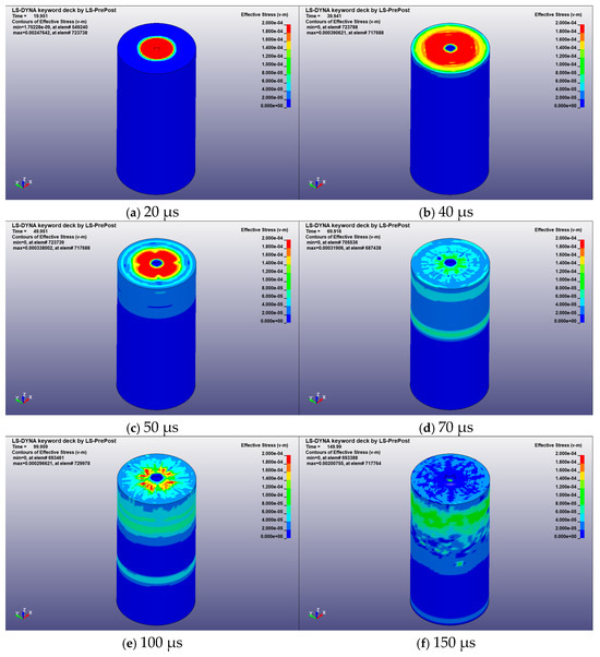
Figure 7.
Stress wave propagation in red sandstone.
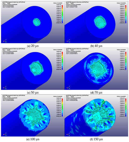
Figure 8.
Crushing Process of Red Sandstone.
In the initial stage of impact loading, stress waves emanate from the loading point and rapidly diffuse outward in a ring-shaped pattern. At this stage, the central area of the rock surface bears extremely high stress, leading to the earliest plastic deformation and the initiation of cracks. However, the extent of crack propagation in both radial and longitudinal directions remains limited, with only minor fissures forming near the impact point, while the overall rock structure largely remains intact without significant signs of failure.
After 20 μs, as the stress waves propagate, the cloud maps clearly show that the stress distribution gradually expands outward. Stress continues to accumulate within the rock and extends radially and longitudinally. As illustrated in Figure 4, Figure 5, Figure 6 and Figure 7, cracks propagate radially from the impact point in a radiation-like pattern, while annular cracks begin to intersect with radial ones, causing small fragments to separate from local regions. At this stage, driven by stress waves, crack propagation and rock fragmentation accelerate. Radial stress wave propagation promotes the growth of radial cracks, while longitudinal propagation drives cracks deeper into the rock, progressively forming an interconnected fracture network.
By 70 μs, in the mid-stage of impact, stress waves have diffused throughout a larger region of the rock, indicating that stress has been largely transmitted through the rock body, though the peak stress remains concentrated in the severely fractured top region. The fracture maps show cracks fully penetrating the rock cross-section, with distinct block separations, particularly severe at the top surface. The propagation of stress waves into deeper regions confirms that energy has been dissipated over a broader volume, though the maximum stress still concentrates near the top.
After 100 μs, stress waves continue to spread toward the bottom and edge regions of the rock, accompanied by ongoing energy dissipation. The cloud maps reveal that the stress distribution gradually becomes more uniform. Although the crack propagation rate begins to slow, the tendency for block separation becomes more pronounced. By the time the stress waves reach the bottom surface, the residual energy is insufficient to initiate new cracks and only accelerates the coalescence of existing cracks, further promoting the detachment and separation of rock blocks.
Overall, owing to its low viscosity and high diffusivity, SC-CO2 can rapidly infiltrate rock pores and pre-existing fractures, generating localized high-pressure zones that reduce effective stress and weaken the cementing material (Figure S1, Supplementary Materials). This process induces a combined failure mode involving tensile and shear mechanisms, manifested as a composite crushing–splitting–shearing pattern, with a clear energy transfer path and spatiotemporal evolution. In the initial impact stage, the high-velocity jet produces stress waves that propagate outward in a ring-like manner, creating a localized crushing zone at the rock surface and initiating crack formation. As the stress waves attenuate, the gas-wedge effect of SC-CO2 dominates crack propagation, with fluid pressure at crack tips driving secondary cracks to extend along the direction of minimum principal stress. This leads to the development of a complex fracture network, significantly enhancing rock permeability. Meanwhile, the phase-change characteristics of SC-CO2 further promote the growth and extension of microfractures. When damage accumulation reaches a critical level, throughgoing failure occurs at the rock surface, crack propagation ceases, and the fracturing process stabilizes.
5. Conclusions
Based on the SPH-FEM coupling method and the RHT constitutive model, this study systematically investigated the rock fracturing process induced by SC-CO2 jets, revealing the fracture patterns and damage mechanisms under varying standoff distances, jet velocities, and lithological conditions. The numerical simulation results not only confirm the superior rock-breaking capability of SC-CO2 compared to conventional water jets, but also further clarify its advantages in energy transfer, crack propagation, and damage evolution. In addition, this study qualitatively incorporates the concept of block size distribution to interpret mesoscale fragmentation characteristics. Although the block size distribution was not explicitly computed, the spatial evolution of damaged zones, failure element volumes, and fracture connectivity patterns effectively reflects the variation in rock block sizes under different jet conditions. Through comparative analysis, the optimal parameter ranges and application scenarios of SC-CO2 jet fracturing in practical rock-breaking operations are identified, providing theoretical guidance for the development of green and efficient rock-fracturing technology. The main conclusions are as follows:
(1) Owing to its low viscosity, high diffusivity, and compressibility, SC-CO2 jet fracturing produces a more extensive fracture network inside the rock, achieving significantly better fracturing efficiency than water jets.
(2) An optimal standoff distance of 1–2 cm was identified. Increasing jet velocity markedly enhances fracturing intensity, with velocities above 0.2 cm/μs exhibiting typical brittle failure characteristics.
(3) Different rocks exhibit varying fracture sensitivity and failure modes. Marble tends to fracture easily even at low velocities, whereas granite requires higher velocities to generate significant cracking.
(4) The SC-CO2 jet fracturing process follows a sequence of stress concentration, radial crack propagation, and longitudinal throughgoing failure, ultimately forming a typical funnel-shaped fracture pattern and greatly improving rock permeability.
(5) The assumption of “no in situ confining pressure” may influence the final results to some extent, and future studies should consider incorporating in situ confining pressure to more accurately reflect the real behavior of SC-CO2 jet fracturing.
(6) Future research will focus on experimental validation and model improvement to more accurately characterize the behavior of SC-CO2 and enhance its engineering applicability. In addition, complex thermodynamic and multiphase flow models should be considered to more realistically describe the phase behavior of SC-CO2 under high-temperature and high-pressure conditions.
Supplementary Materials
The following supporting information can be downloaded at: https://www.mdpi.com/article/10.3390/app152111357/s1, Figure S1: Failure Element Volume; Table S1: Diatite RHT constitutive model parameters; Table S2: RHT constitutive model parameters for red sandstone; Table S3: Granite RHT constitutive model parameters; Table S4: Sensitivity coefficient of different parameters of marble; Table S5: Sensitivity coefficient of different parameters of red sandstone; Table S6: Sensitivity coefficient of different granite parameters.
Author Contributions
Conceptualization, Y.L. and T.M.; methodology, C.L.; software, C.L.; validation, Y.L., L.S. and X.T.; formal analysis, K.P.; investigation, K.L.; resources, C.L.; data curation, L.S.; writing—original draft preparation, Y.L.; writing—review and editing, T.M.; visualization, T.M.; supervision, T.M.; project administration, Y.L.; funding acquisition, Y.L. All authors have read and agreed to the published version of the manuscript.
Funding
This research was funded by the National Key Research and Development Program of China (Grant No. 2021YFC2900400), the National Key Research and Development Program of China–2023 Key Special Project (Grant No. 2023YFC2907400), The Seed Fund Cultivation Project of Ocean College, Zhejiang University (2025BS002).
Institutional Review Board Statement
Not applicable.
Informed Consent Statement
Not applicable.
Data Availability Statement
Data will be made available on request.
Conflicts of Interest
The authors declare that they have no known competing financial interests or personal relationships that could have appeared to influence the work reported in this paper.
References
- Zhang, R.; Lv, C.-J.; Ren, Q.-K.; Wang, Y.; Liao, Y.; Zhang, Z. A new fracability evaluation model for complex lithologies fractured shale oil reservoir. Therm. Sci. 2024, 28, 1121–1126. [Google Scholar] [CrossRef]
- Lind, S.J.; Rogers, B.D.; Stansby, P.K. Review of smoothed particle hydrodynamics: Towards converged Lagrangian flow modelling. Proc. R. Soc. A Math. Phys. Eng. Sci. 2020, 476, 201908001. [Google Scholar] [CrossRef]
- Assefa, E.; Tilahun, K.; Assefa, S.M.; Jilo, N.Z.; Pantelidis, L.; Sachpazis, C. Stability evaluation of tunnels in steeply dipping layered rock mass using numerical models: A case study. Sci. Rep. 2025, 15, 2046. [Google Scholar] [CrossRef]
- Steiakakis, E.; Xiroudakis, G.; Lazos, I.; Vavadakis, D.; Bazdanis, G. Stability Analysis of a Multi-Layered Slope in an Open Pit Mine. Geosciences 2023, 13, 359. [Google Scholar] [CrossRef]
- Zhang, C.; Ye, J.; Liu, N.; Xie, Q.; Hu, M.; Li, L. True triaxial modeling test of high-sidewall underground caverns subjected to dynamic disturbances. J. Rock Mech. Geotech. Eng. 2025, 17, 2109–2132. [Google Scholar] [CrossRef]
- Xie, S.; Jiang, Z.; Lin, H.; Ma, T.; Peng, K.; Liu, H.; Liu, B. A new integrated intelligent computing paradigm for predicting joints shear strength. Geosci. Front. 2024, 15, 101884. [Google Scholar] [CrossRef]
- Suboyin, A.; Rahman, M.; Haroun, M. Hydraulic fracturing design considerations, water management challenges and insights for Middle Eastern shale gas reservoirs. Energy Rep. 2020, 6, 745–760. [Google Scholar] [CrossRef]
- Ma, T.; Hu, X.; Liu, H.; Peng, K.; Lin, Y.; Chen, Y.; Luo, K.; Xie, S.; Han, C.; Chen, M. Elastic modulus prediction for high-temperature treated rock using multi-step hybrid ensemble model combined with coronavirus herd immunity optimizer. Measurement 2025, 240, 115596. [Google Scholar] [CrossRef]
- Qiu, X.; Shen, W.; Guo, Z.; Chen, H.; Shi, X. Effect of in-situ stresses on fracturing performance of crater blasting under different resistance lines. J. Cent. South Univ. 2023, 30, 2686–2700. [Google Scholar] [CrossRef]
- Ma, T.; Chen, C.; Shen, L.; Luo, K.; Jiang, Z.; Liu, H.; Hu, X.; Lin, Y.; Peng, K. A novel social network search and LightGBM framework for accurate prediction of blast-induced peak particle velocity. Front. Struct. Civ. Eng. 2025, 19, 645–662. [Google Scholar] [CrossRef]
- Xue, H.; Gao, Y.; Zhang, X.; Tian, X.; Wang, H.; Yuan, D. Directional Blasting Fracturing Technology for the Stability Control of Key Strata in Deep Thick Coal Mining. Energies 2019, 12, 4665. [Google Scholar] [CrossRef]
- Yin, H.; Zhou, J.; Jiang, Y.; Xian, X.; Liu, Q. Physical and structural changes in shale associated with supercritical CO2 exposure. Fuel 2016, 184, 289–303. [Google Scholar] [CrossRef]
- Weißenfels, C. Simulation of Additive Manufacturing Using Meshfree Methods; Springer Nature: Durham, NC, USA, 2022. [Google Scholar]
- Pan, C.; Xie, L.; Li, X.; Liu, K.; Gao, P.; Tian, L. Numerical investigation of effect of eccentric decoupled charge structure on blasting-induced rock damage. J. Cent. South Univ. 2022, 29, 663–679. [Google Scholar] [CrossRef]
- Cai, C.; Wang, B.; Huang, Z.; Yue, W.; Wang, H.; Gao, Y.; Feng, Y.; Yang, Y.; Gao, C. Comparison with the effect of the cyclic liquid nitrogen jet and liquid nitrogen immersion cooling on the deterioration of mechanical properties of high temperature rocks. Geoenergy Sci. Eng. 2024, 243, 213295. [Google Scholar] [CrossRef]
- Li, J.; Zhang, G.; Liu, H.; Li, J.; Zhang, S.; Cheng, X. Study on Influencing Factors of Liquid Carbon Dioxide Blasting in Rock Cutting. Recent Pat. Eng. 2024, 18, 140–151. [Google Scholar] [CrossRef]
- Huang, M.; Kang, Y.; Wang, X.; Hu Yi Li, D.; Cai, C.; Chen, F.; Coelho, A. Effects of Nozzle Configuration on Rock Erosion Under a Supercritical Carbon Dioxide Jet at Various Pressures and Temperatures. Appl. Sci. 2017, 7, 606. [Google Scholar] [CrossRef]
- Wang, H.; Li, G.; He, Z.; Shen, Z.; Wang, M.; Wang, Y. Mechanism study on rock breaking with supercritical carbon dioxide jet. At. Sprays 2017, 27, 383–394. [Google Scholar] [CrossRef]
- Wang, Z.; Zhong, J.; Pan, C.; Jiang, Y. Application of supercritical carbon dioxide jet to recycle waste tire rubber: An experimental and optimization study. J. Supercrit. Fluids 2023, 192, 105790. [Google Scholar] [CrossRef]
- Cai, C.; Li, B.R.; Zhang, Y.Y.; He, W.; Yang, Y.; Kang, Y.; Wu, J. Fracture propagation and induced strain response during supercritical CO2 jet fracturing. Pet. Sci. 2022, 19, 1682–1699. [Google Scholar] [CrossRef]
- Cheng, Y.; He, D.; Ma, T.; Lin, H.; Hu, X.; Liu, H. Hybrid data-driven model and shapley additive explanations for peak dilation angle of rock discontinuities. Mater. Today Commun. 2024, 40, 110194. [Google Scholar] [CrossRef]
- Mukun, L.; Gang, W.; Weimin, C.; Pu, S.; Ni, H.; Shi, X. Heat-fluid-solid coupling mechanism of supercritical carbon dioxide jet in rock-breaking. Pet. Explor. Dev. Online 2021, 48, 1450–1461. [Google Scholar]
- Wang, C.; Shi, X.; Zhang, W.; Elsworth, D.; Cui, G.; Liu, S.; Wang, H.; Song, W.; Hu, S.; Zheng, P. Dynamic analysis of heat extraction rate by supercritical carbon dioxide in fractured rock mass based on a thermal-hydraulic-mechanics coupled model. Int. J. Min. Sci. Technol. 2022, 32, 225–236. [Google Scholar] [CrossRef]
- Yang, C.; Hu, J.; Ma, S. Numerical investigation of rock breaking mechanism with supercritical carbon dioxide jet by SPH-FEM approach. IEEE Access 2019, 7, 55485–55495. [Google Scholar] [CrossRef]
- Ma, T.; Luo, R.; Shen, L.; Ye, B.; Wang, X.; Sun, H. Modified Herschel–Bulkley–Papanastasiou model considering particle size distribution to debris flow rheological properties. Phys. Fluids 2025, 37, 023127. [Google Scholar] [CrossRef]
- Linforth, S.; Tran, P.; Rupasinghe, M.; Nguyen, N.; Ngo, T.; Saleh, M.; Odish, R.; Shanmugam, D. Unsaturated soil blast: Flying plate experiment and numerical investigations. Int. J. Impact Eng. 2018, 125, 212–228. [Google Scholar] [CrossRef]
- Song, S.; Xu, X.; Ren, W.; Liu, S.; Jiang, J. Determination and application of the RHT constitutive model parameters for ultra-high-performance concrete. Structures 2024, 69, 107488. [Google Scholar] [CrossRef]
- Xu, H.; Wen, H. A computational constitutive model for concrete subjected to dynamic loadings. Int. J. Impact Eng. 2016, 91, 116–125. [Google Scholar] [CrossRef]
- Hooman, R.; Mehdi, A.; Ebrahim, F. Investigating the effects of confining pressure and loading rate on damage propagation and mode I stress intensity factor of granite using the RHT constitutive model. Geomech. Geophys. Geo-Energy Geo-Resour. 2025, 11, 79. [Google Scholar]
- Gholamhossein, S.; Hamidreza, B.; Mohsen, A.; Majid, N. Solubility measurement of Ceftriaxone sodium in SC-CO2 and thermodynamic modeling using PR-KM EoS and vdW mixing rules with semi-empirical models. Case Stud. Therm. Eng. 2024, 61, 105074. [Google Scholar]
- Yang, S.; Jesus, A.; Meng, D.; Nie, P.; Darabi, R.; Azinpour, E.; Zhu, S.; Wang, Q. Very high-cycle fatigue behavior of steel in hydrogen environment: State of the art review and challenges. Eng. Fail. Anal. 2024, 166, 108898. [Google Scholar] [CrossRef]
- Meng, D.; Li, Y.; He, C.; Guo, J.; Lv, Z.; Wu, P. Multidisciplinary design for structural integrity using a collaborative optimization method based on adaptive surrogate modelling. Mater. Des. 2021, 206, 109789. [Google Scholar] [CrossRef]
- Guo, Y.; Meng, D.; Pan, L.; Zhang, J.; Yang, S. Reliability evaluation of precision hot extrusion production line based on fuzzy analysis. Structures 2024, 64, 106553. [Google Scholar] [CrossRef]
- Zhang, M.; Yang, L.; Zhang, Z.; Chen, L.; Li, Y. The influence of SC-CO2 on the shales’ fracture behavior described by using ultra-fast time resolution method and the damage fracture constitutive model: A case study of the Cretaceous Qingshankou formation in Gulong Depression, Songliao Basin, NE China. Theor. Appl. Fract. Mech. 2024, 134, 104705. [Google Scholar] [CrossRef]
- He, C.; Mishra, B.; Yuan, W.; Waang, X.; Shi, Q. Investigation of the dynamic behavior and fracturing mechanism of granite. Fuel 2024, 360, 130579. [Google Scholar]
- Herrmann, W. Constitutive equation for the dynamic compaction of ductile porous materials. J. Appl. Phys. 1969, 40, 2490–2499. [Google Scholar] [CrossRef]
Disclaimer/Publisher’s Note: The statements, opinions and data contained in all publications are solely those of the individual author(s) and contributor(s) and not of MDPI and/or the editor(s). MDPI and/or the editor(s) disclaim responsibility for any injury to people or property resulting from any ideas, methods, instructions or products referred to in the content. |
© 2025 by the authors. Licensee MDPI, Basel, Switzerland. This article is an open access article distributed under the terms and conditions of the Creative Commons Attribution (CC BY) license (https://creativecommons.org/licenses/by/4.0/).