Challenges for construction processes and opportunities that must be permanently monitored to ensure the adequate building, correct operation, and adequate level of safety of these structures are discussed and analyzed in this section. Also, climate threats, extreme geological events such as earthquakes, and the deterioration of bridge materials due to high use affect bridge structural stability and functionality. Finally, some aspects of architecture, engineering, construction, and structural health monitoring (AECSHM) of bridges are discussed.
4.1. Challenges in New Digital Technology Tools to Support Bridge Construction
Currently, a series of digital tools are being implemented in Peru to improve aspects of efficiency and precision in bridge infrastructure construction activities. Thus, in many projects, the installation of prefabricated or modular structural elements in both concrete and steel is being implemented. In the case of concrete, prestressed concrete beams or slabs and post-tensioned concrete, which allows for longer-span beams reaching 40 m, are used.
Regarding steel elements, some sections or segments are part of the deck of cable-stayed bridges or suspension bridges, where 10 m long units can be assembled and mounted as modular pieces. On the other hand, there is the use of BIM (Building Information Modeling), which consists of a 5D virtual model of the bridge infrastructure to be built, studying the progress of the project both on the spatial scale and on the temporal scale. A virtual three-dimensional model is generated with all the structural elements and their environment, also coupling a fourth 1D dimension with the construction processes and programming over time, and finally adding a fifth 1D dimension by adding construction costs and expenses to the model [
19,
20,
21].
Finally, it is important to mention the use of UAVs or drones to support the construction aspects of bridge projects, where it is possible to (i) make topographic surveys of the study sector using LiDAR systems, (ii) take photographs of the construction process and analyze its evolution over time, generating a 3D model using photogrammetry, and (iii) generate heat maps of the built infrastructure and identify areas of failure or weakness of sensitive or vulnerable structural elements through the use of thermal cameras. The use of UAVs allows for significant time savings in generating 3D models and avoids the risk of personnel accidents when accessing complex construction conditions [
22,
23,
24,
25,
26].
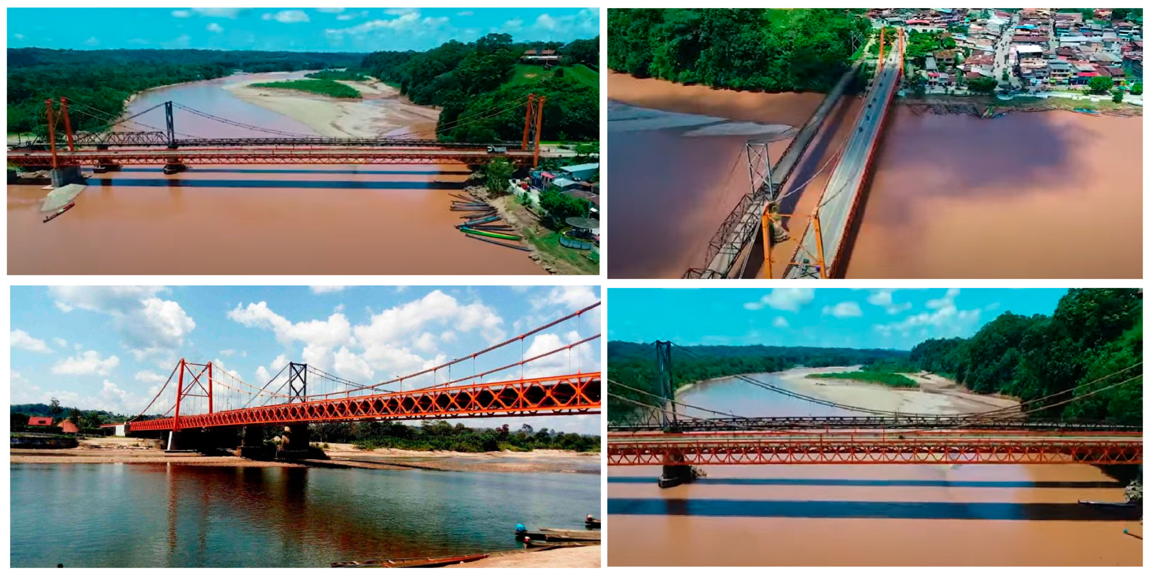
The first example is the Nanay Cable-Stayed Bridge Project, where the BIM (Building Information Modeling) and DfMA (Design for Manufacturing and Assembly) methodologies were implemented. The application of these methodologies in this project was a cutting-edge milestone in Peru, since it was the first time that a large-scale infrastructure project had implemented this new construction concept in the country. The lack of significant sources of aggregates for concrete in the project location (jungle of Peru) was an important factor in selecting composite “steel–concrete” solutions, allowing the designer to minimize the use of concrete. In this sense, a composite cable-stayed bridge was the concept with a competitive edge solution [
27,
28].
The Nanay cable-stayed bridge was designed to be built using successive cantilevers with 10 m segments, symmetrically, on each side of each of the pylons. The project considered that the assembly of the steel structure was carried out using mobile lifting systems. Each steel structure module is made up of two main lateral plate girder beams of 1.5 m height and an interior central beam of 0.3 m height, transverse beams spaced every 3.5 m, stiffeners, bolts and shear connectors. On the other hand, the deck slab was designed to be made from reinforced concrete, which is made up of prefabricated panels that are monolithically joined together by means of concrete joining strips built in situ. In addition, the substructure of the Nanay bridge is made up of an abutment and a pylon on each side of the Nanay River. The foundation is deep, using piles dug 60 m deep and with a diameter of 2 m. Finally, the bridge accesses, both on the left and right banks, are of a frame type with reinforced concrete columns and a crossbeam.
For the execution of the piles, an operations platform was previously prepared, which had to be 2 m above the water table or the maximum water level for the construction period. The construction of the piles was not carried out within the Nanay River. To achieve this, the span and total length of the bridge were increased. Thus, the piles were located outside the width of the river’s water surface in order to carry out the construction work during the dry season of the Nanay River (May–October). The piles were built with benthic mud support and materialized with reinforced concrete.
On the other hand, after the piles were built, the construction of the pylons considered the following phases: (i) construction of the deep foundations, (ii) construction of columns below the level of the lower crossbeam, (iii) construction of the lower crossbeam, (iv) construction of the column base above the level of the lower crossbeam, (v) construction of columns above the level of the lower crossbeam, (vi) construction of the upper crossbeam, and (vii) construction of columns above the level of the upper crossbeam.
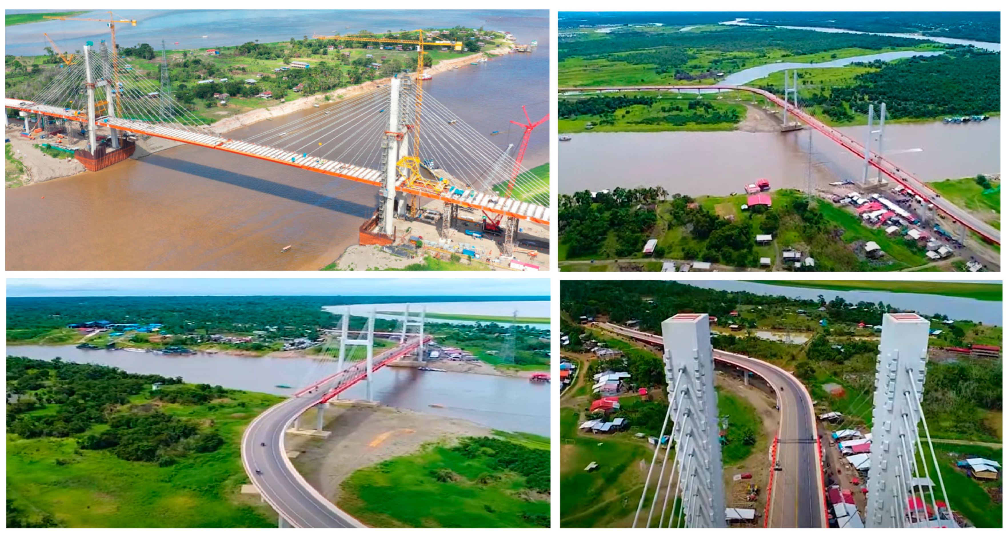
The bridge deck was then built using successive 10 m segmental cantilevers. The segments are composite sections, with plate girder steel beams and concrete slabs joined by shear connectors. The elements of the metal structure were manufactured in the city of Lima, where they were then transported to the project area. The concrete slabs were prefabricated in the civil works area, and after assembly, they were joined by concrete strips built on-site. This is how the segment assembly used mobile lifting systems (see
Figure 16).
In the above, the sequence of assembly of the segments was as follows: (i) The elements of the metal structure that are in the river raft were lifted by means of cables by the mobile lifting systems up to the level of the bridge deck work area. (ii) The metal elements were assembled by joining the lifted elements to the previous segment by means of connection bolts by the assembly operators. (iii) Once the assembly of the metal segment was finished, the metal segment was connected to the respective stay or cable, which was anchored in the pylon. (iv) The prefabricated slab panels were then lifted from the raft, and the concrete panels were placed on the template of the metal segment already assembled and supported by the stay cables of the bridge. (v) Four mobile lifting systems were used, two for each pylon, and each system was provided at its front with two hydraulic lifting jacks. (vi) The union between concrete panels was made by means of concrete strips that were placed on-site, where the stay cables were then tensioned, inducing significant pre-compression in the concrete slab. The construction process described above was supported by two high-lift cranes located on the side of each of the bridge pylons (see
Figure 17).
Finally, the aerodynamic stability of the bridge was analyzed. In this sense, at the location of the Nanay bridge, the Peruvian Design Code establishes a design wind speed of 95 km/h at 10 m above the ground for a return period of 50 years. Despite the use of a torsional weak open section, the use of an H-pylon configuration with two planes of cables allowed the bridge to achieve a ratio that is within the limits to prevent flutter instability. Wind tunnel testing was conducted to further ensure the stability of the bridge during construction and operation.
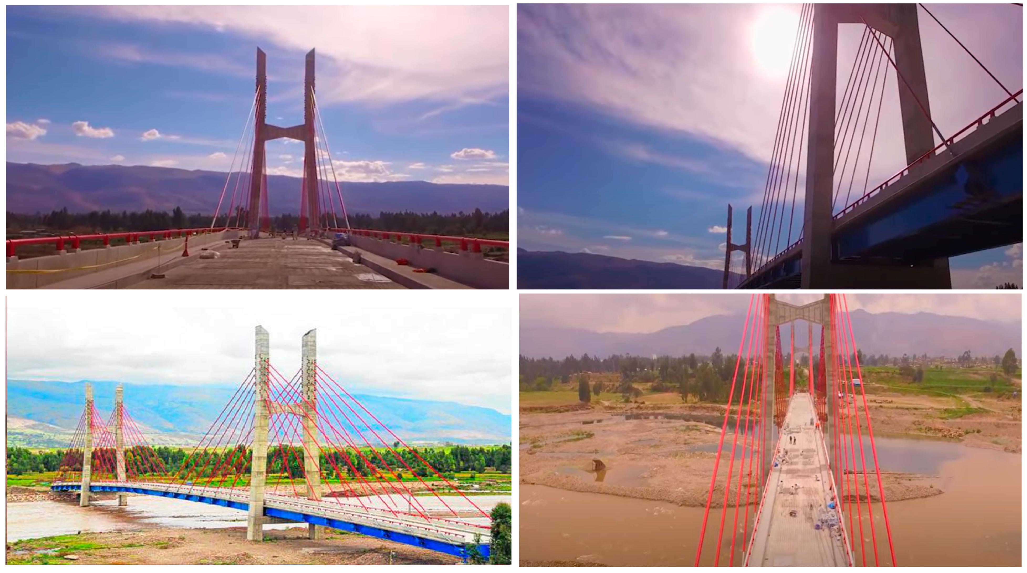
A second example corresponds to the La Joya Virgen de Chapi Bridge Project, where the bridge is of a structural steel arch type, where the BIM (Building Information Modeling) methodology was implemented together with the DfMA (Design for Manufacturing and Assembly) concept with the following purposes: (i) carry out the collaborative work of the different project actors, (ii) reduce errors, deviations, and uncertainties as much as possible in the engineering, construction, and project management stages, and (iii) control the risks of the construction process, considering the industrial manufacturing of components (avoiding on-site work if possible), transportation, and assembly of different elements of the bridge infrastructure, among others.
First, through BIM, which involved a virtual model of the La Joya Virgen de Chapi bridge, it was possible to properly coordinate the activities of the different actors, such as designers, construction contractors, supervisor or inspectors of civil works, and clients. This is how the entire technical file of the project, such as calculation reports, engineering drawings, technical specifications, and manuals, was properly managed using BIM, reducing interference and optimizing the time of professionals from different disciplines such as architecture, civil engineering, hydraulic engineering, hydrology, geotechnical engineering, structural engineering, road engineering, and topography, among others (see
Figure 18).
Second, through BIM, it was possible to reduce a large number of possible errors, deviations, and uncertainties in (i) the project’s engineering documents and drawings, (ii) the construction processes of the infrastructure on site, adequately coordinating the scheduling of the construction times of each civil works activity within reasonable time frames, and (iii) the adequate control of the expenses and costs of the work through effective management of human resources, machinery resources, material resources, and financial resources [
30].
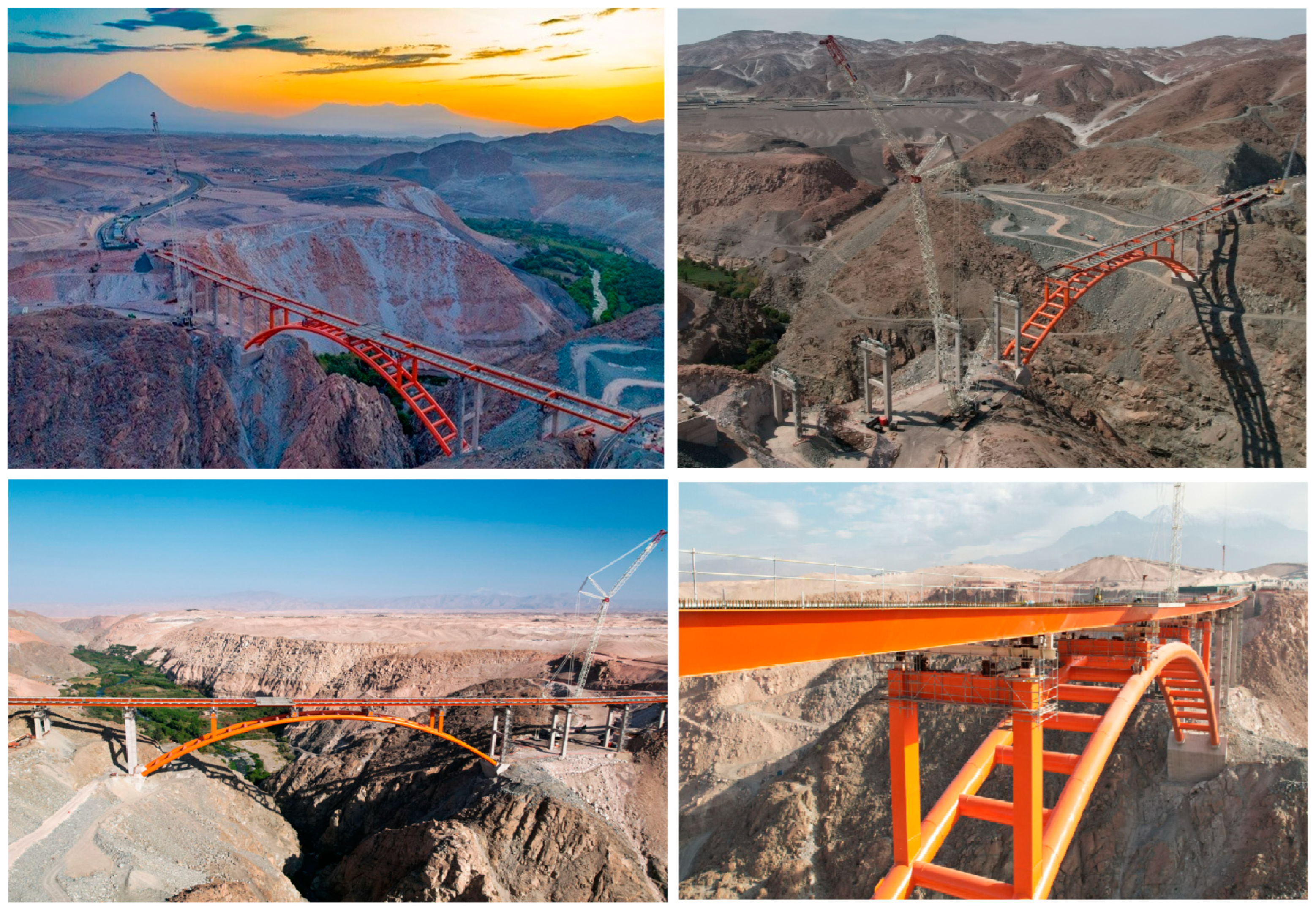
Also, third, by integrating the BIM methodology with the DfMA (Design for Manufacturing and Assembly) concept, a modular construction process for the arch structure was implemented, where the arch was built using steel metal parts manufactured in a factory in Italy under controlled quality conditions. Once the different pieces of the arch were made, they were transported by ship to Peru, where they were then transported by truck from the port of Callao to the project area. Once the pieces were at the project site, assembly activities were carried out using cranes, materializing the construction of the arch in two parts. In addition, assembly was carried out to ensure the proper connection between each of the pieces. Finally, once the assembly of the arch on site was finished, the installation of the bridge deck was carried out by launching the section of said structure from one abutment to another abutment using cables and hydraulic jacks.
The implementation of the BIM and DfMA methodologies has allowed for substantial improvements in the performance of bridge design/construction projects in Peru. For example, it is possible to mention that reductions in construction times of around 20% have been achieved; in addition, a decrease in construction costs of 15% has been recorded, and the amount of waste on site has also been reduced by 10% (See
Figure 19).
Finally, this article presents an incipient and promising paradigm shift, from building to DfMA, in bridge infrastructure projects in Peru, fostering the displacement of workers from on-site to off-site activity, and the expansion of interdisciplinary architecture, engineering, construction, and structural health monitoring (AECSHM) collaboration [
31,
32,
33].
Lean construction is a project management approach for bridge construction that is being applied in South America, specifically in Peru, which helps in the design of construction systems in a dynamic environment [
30]. The objective is to maximize value for the client through a permanent effort focused on eliminating and reducing waste, a term that is complex to visualize but that, once materialized and applied, helps in exponentially improving construction processes.
In both South America and Peru, lean construction has been applied effectively, paying attention to the principles of this work methodology [
34,
35]:
Eliminate everything that does not add value: The main basis of this work methodology refers to the elimination of the steps from the workflow that do not add any type of value to the product (building, housing, road, highway, bridge, civil work, industrial work, etc.).
Add value to construction: Before starting the project itself, it is essential to have a clear understanding of the client’s needs. All designers involved in the work must participate in alignment meetings and have an in-depth knowledge of the profile of the audience for each project. In this way, it is possible to develop competitive advantages and deliver works that really make sense for the end consumer.
Reduce variability: Standardized processes are essential for lean construction. Although each project has its peculiarities and it is almost impossible to escape unforeseen events, it is always possible (and ideal) to adopt work patterns that reduce variation between one project and another. In this way, the project becomes uniform and consistent, with more satisfied clients upon delivery of the work.
Just in time: A lack of planning over time can lead to losses and delays. Therefore, one of the principles of lean construction is the optimization of work cycles, i.e., the time needed to perform tasks. With good planning, it is possible to deliver work in a shorter time, have employees focused on specific tasks, and have a more accurate estimate of work steps.
Make processes transparent: Transparent construction management makes it easier to identify points of error, as all the necessary information is always available to the people who need it. To have more transparent processes and ensure continuous improvement, it is essential to be simple, reduce friction, eliminate visual obstacles on the construction site, have an open communication flow, and ensure a comfortable work environment.
4.4. Opportunities for Structural Health Monitoring of Bridges Against Deterioration Due to Use of Materials
An important issue that must be monitored through continuous monitoring over time is the effect of the deterioration of materials due to environmental conditions in the bridge infrastructure project. Cycles of night and day temperature changes, cycles of temperature changes from winter to summer, moisture content, liquid and solid precipitation, among others, cause internal changes and alterations in the construction materials used in bridges, such as wood, concrete, and steel. These environmental conditions induce deformations, displacement, rotations, sulfation, and corrosion, among others, in bridge infrastructure [
38,
42,
43]. By combining wireless sensors with the use of the IoT and artificial intelligence, it is possible to measure different parameters and monitor changes in the key properties of structural elements in bridges in real time [
42,
44]. The use of UAVs or drones that have thermal cameras allows for obtaining heat maps of the structural elements of bridges and identifying areas of cracking and fracture in reinforced concrete structures and excessive corrosion in steel structures. The use of UAVs allows the bridge to continue providing normal operation to the public without traffic interruptions day or night [
22,
23]. Nevertheless, creep and shrinkage effects have to be considered in terms of long-term behavior for the structural health monitoring of bridge infrastructures. In this sense, precast deck systems also have several advantages from a construction point of view, such as superior concrete quality, the possibility of implementing a modular construction scheme, and the fact that there are fewer weather constraints, since the volumes of cast-in-place concrete are significantly reduced. For example, for the Nanay bridge, pre-cast slab panels with dimensions of 3.20 m × 7.30 m, cured at least 60 days before their installation on the bridge, were used to minimize creep and shrinkage effects.
Structural health monitoring for bridge structures generally refers to the process of designing, developing, and implementing a damage detection or characterization strategy for the real-time assessment of structural conditions.
A typical structural health monitoring system includes four main components:(i) A sensor network, (ii) data processing system (including data acquisition, transmission, and storage), (iii) a health assessment system to support decision-making, and (iv) manual inspection by engineers and risk-reduction specialists.
The structural health monitoring process generally involves monitoring a structure over a certain period of time, either short- or long-term, using an appropriate set of sensors and devices.
Likewise, manual monitoring must be complemented with online digital monitoring. It is important that engineers and specialists also carry out on-site inspections, observing possible damage to the structure, to define levels of deterioration/vulnerabilities and make better decisions.


