Abstract
This study proposes a hybrid optimization algorithm (IFWA-SA) integrating an improved fireworks algorithm with simulated annealing for sparse array synthesis in multiple-input multiple-output (MIMO) radar systems. The innovation lies in synergistically combining the multidimensional directional explosion mechanism of the fireworks algorithm for global exploration with simulated annealing’s probabilistic jumping strategy for local optimization. Initial populations generated via Sobol sequences eliminate local clustering from random initialization. During global exploration, the proposed discrete variant of the fireworks algorithm, tailored for sparse array optimization, significantly enhances the search efficiency, while temperature-controlled probabilistic optimization refines array aperture and element spacing to escape local optima during local refinement. Comparative experiments with particle swarm optimization (PSO), simulated annealing (SA), genetic algorithm (GA) and gray wolf optimization (GWO) demonstrated that the proposed method effectively suppresses sidelobes. On average, the IFWA-SA reduced the peak sidelobe level (PSL) by about 1.3–3.8 dB compared with the benchmark algorithms, confirming its superior convergence capability and effectiveness in synthesizing high-performance sparse arrays.
1. Introduction
Multiple-Input Multiple-Output (MIMO) radar has emerged as a prominent area of research in the field of radar due to its remarkable capabilities in spatial diversity, frequency diversity, and waveform diversity. These capabilities enable the formation of larger observation apertures and higher sampling densities, thereby facilitating enhanced surveillance capabilities and accuracy [1,2,3]. However, the prevailing array configurations typically employ common topologies, such as a uniform line array, a parallel line array, or a uniform circular array. The multi-receiver and multi-transmitter systems inherent to these structures frequently result in an escalation in system complexity, thereby impeding the engineering and practicality of radar systems. In contrast, sparse array technology enhances the virtual aperture by increasing element spacing, which suppresses mutual coupling, reduces noise correlation, and leverages low redundancy to minimize resource waste. These improvements collectively boost computational efficiency. Consequently, integrating sparse arrays with MIMO radar sparsification has emerged as a pivotal trend in modern radar systems [4,5,6].
Sparse array optimization has been demonstrated to enhance antenna performance by strategically adjusting the positions of array elements. The optimization and design methodologies of traditional linear arrays can be categorized into five distinct approaches: metaheuristic algorithms [7], Fourier transform-based synthesis [8], convex optimization [9], matrix decomposition techniques [10], and compressed sensing [11]. In comparison to conventional arrays, MIMO radar arrays necessitate the consideration of both transmitting and receiving arrays, thereby increasing their complexity. Metaheuristic algorithms have emerged as vital tools for antenna array synthesis due to their superior convergence characteristics and robust optimization capabilities. Compared with conventional optimization methods, these nature-inspired techniques demonstrate three notable advantages: rapid convergence speed, enhanced global search ability, and exceptional resilience in addressing complex electromagnetic problems. These merits have facilitated their extensive adoption in sparse array optimization. Successful implementations include particle swarm optimization (PSO) [12], the genetic algorithm (GA) [13], ant colony optimization (ACO) [14], the invasive weed optimization (IWO) algorithm [15], the artificial bee colony (ABC) algorithm [16], harmony search (HS) [17], spider monkey optimization (SMO) [18], antlion optimization (ALO) [19], the cuckoo search algorithm (CS) [20], the grasshopper optimization algorithm (GOA) [21], gray wolf optimization (GWO) [22], the mayfly algorithm (MA) [23], and the jellyfish search (JS) algorithm [24].
Recent advancements have expanded these techniques through algorithmic innovations. Sun et al. [25] improved the binary brainstorming optimization (ImBBSO) method in three ways and used it for pattern synthesis of linear sparse arrays. Wang et al. [26] proposed a Teaching Quality Evaluation Based Differential Evolutionary Algorithm (TQEDE) by combining Levy flight and adaptive parameter optimization. Li et al. [27] first applied the dandelion optimization (DO) algorithm to linear antenna array radiation pattern synthesis, achieving ultra-low sidelobes and deep nulls through optimization of excitation amplitudes and element spacing. Zhao et al. [28] proposed the chaotic inertia-weighted wild horse optimization algorithm (IERWHO), which enhances optimization performance through chaotic initialization and nonlinear parameter adaptation. Mou et al. [29] employed the sand cat swarm optimization algorithm (SCSO) for array synthesis to optimize multiple parameters while accounting for mutual coupling effects.
Aiming to address the limitations of existing stochastic optimization methods, such as slow convergence and susceptibility to local optima, this paper proposes an improved fireworks-simulated annealing algorithm. A Sobol sequence is used to generate the initial population to improve the uniform distribution of the population. Given the discrete nature of the array optimization problem, the conventional fireworks algorithm was adapted into a discrete variant to enhance its applicability to sparse array synthesis. Furthermore, by integrating the annealing mechanism from simulated annealing into the improved fireworks algorithm, the proposed method effectively suppresses peak side lobe levels while maintaining fast convergence during sparse array optimization.
The rest of the paper is structured as follows: Section 2 presents the MIMO radar sparse array signal model. Section 3 details the fundamental mechanics of the fireworks algorithm (FWA), proposes innovative strategies for the enhanced IFWA-SA algorithm, and provides a comprehensive optimization workflow with mathematical formulations. Section 4 demonstrates the effectiveness of the IFWA-SA algorithm through four comprehensive simulation case studies. Section 5 concludes the paper.
2. MIMO Sparse Array Signal Model
The objective of this section is to establish a mathematical model for the array optimization problem. It is essential to emphasize that the number of transmitting elements Nt, the number of receiving elements Nr, and their respective physical apertures Lt and Lr serve as predetermined constraints in this study. These constraints collectively determine the theoretical performance bound of the virtual array. In particular, the maximum virtual aperture Lv = Lt + Lr defines the fundamental limit of angular resolution.
Under this framework, the degrees of freedom in the optimization are confined to the distribution of element positions and the weighting coefficients. In this work, the weighting coefficients are fixed at unity (i.e., uniform weighting is applied), thereby focusing the optimization solely on the element positions. This approach provides a more effective strategy for achieving optimal performance in peak sidelobe level (PSL) suppression.
Among various performance metrics, the peak sidelobe level (PSL) is selected as the primary optimization objective, based primarily on the following three considerations:
Mission Relevance: In strong clutter environments, a globally low sidelobe level generally contributes more significantly to overall system performance in target detection compared to deep local nulls or extremely high mainlobe sharpness;
Physical Constraints: The mainlobe width is largely constrained by the total system aperture, leaving limited room for further improvement. In contrast, PSL is highly sensitive to the array element layout, offering greater potential for optimization;
Algorithm Robustness: Optimizing for PSL does not require prior knowledge of interference directions, making the results applicable to a wider range of sensing scenarios and enhancing the generalizability and practicality of the method.
MIMO radar sparse array optimization aims to enhance system robustness under varying operational conditions while simultaneously improving spatial resolution, reducing peak sidelobe levels (PSLs), and increasing signal-to-noise ratio (SNR) through strategic antenna placement. To achieve these objectives, this study adopts the PSL of the equivalent virtual transceiver beam pattern as the optimization criterion, defined as
where is the sum of the weight coefficients; is the sum of the weight coefficients; The mainlobe region is intelligently distinguished from the sidelobe regions by introducing the parameter . By excluding the mainlobe from the calculation of sidelobe peaks, this approach ensures that the optimization process effectively suppresses sidelobe levels without unduly broadening the mainlobe. and denotes the integrated filter output at the receiver. The parameter is expressed as:
where is the scanning direction and is the observation direction.
In the synthesis of sparse arrays, two primary modeling approaches are prevalent. The first is the continuously apertured sparse array, where element positions are freely optimized within a continuous spatial domain. The second is the uniform-grid-based sparse array, where element placement is constrained to predefined grid points, typically integer multiples of a half-wavelength (λ/2).
Although the former approach offers greater degrees of freedom and the potential for superior beam pattern performance, its optimization process can yield unrealistically small inter-element spacings. These sub-wavelength spacings conflict with the physical dimensions of practical antenna elements and exacerbate mutual coupling effects, thereby severely compromising practical implementation.
In contrast, the uniform-grid-based approach avoids excessively close element spacing by imposing a minimum inter-element distance constraint equal to the grid size (typically ≥ λ/2). This ensures physical realizability. Furthermore, this formulation transforms the design problem from continuous-variable optimization to discrete combinatorial selection—specifically, identifying an optimal subset of grid points for element placement. While the resulting combinatorial problem is NP-hard, its discrete nature allows for the application of well-established discrete optimization techniques. This improves the robustness, reproducibility, and practical applicability of the obtained solutions.
Furthermore, constraining the element positions to integer multiples of λ/2 not only complies with the minimum spacing requirement in array physical design, but also ensures theoretical symmetry of the radiation pattern. As a result, the spatial spectrum scanning interval can be reduced to [0, 1]. A brief derivation of this property is provided below [30].
The general expression for the radiation pattern of an arbitrary structured array under the far-field narrowband assumption is:
where denotes the weighting coefficients and represents the element positions. The following expression can then be derived:
When the weighting coefficients are real-valued, the relation holds. Therefore, the power spectrum of the radiation pattern satisfies:
This implies that when the element positions are constrained to integer multiples of λ/2, the radiation pattern exhibits symmetry about u = 1. Furthermore, since the radiation pattern of any linear array satisfies even symmetry, i.e., p(u) = p(−u), the pattern originally defined over u ∈ [−2, 2] can be fully characterized within the interval u ∈ [0, 1] under this constraint. Therefore, this study is conducted under the constraint that element positions are restricted to integer multiples of λ/2.
The integrated virtual equivalent transceiver beam consists of two levels, one for conventional beam formation and the other for virtual equivalent transmit beam formation, and the integrated effect is the product of the beam responses of the two levels. This paper investigates a single base MIMO radar based on far-field conditions. In this case, it can be considered that the azimuth angles of the transmit and receive arrays are approximately the same, and the array element spacing of both the transmit and receive arrays is an integer multiple of the half-wavelength.
For a system with M transmit elements and N receive elements, the integrated receiver output is formulated as:
where of the transmit direction map; and are the weighting coefficients of the beam formation at the transmitter and receiver (when only the position of the array element is optimized, the weighting coefficients ), The steering vectors and for the desired direction are defined as:
where and denote the positions of the transmitting and receiving array elements, respectively, with the expression:
Sparse arrays occupy fixed -spaced grids. Their positions can be represented by binary codes. For example, a transmit element position vector [0, 1, 2, 6] (in units) corresponds to the binary code [1, 1, 1, 0, 0, 0, 1]. Here, “1” indicates an element exists at the grid, while “0” indicates no element.
3. Related Algorithms
3.1. Traditional Fireworks Algorithm (FWA)
As a population optimization algorithm, the traditional fireworks algorithm is inspired by the phenomenon of fireworks exploding in the night sky. This algorithm typically incorporates four core components: (1) Explosion Operator, (2) Mutation Operator, (3) Mapping Rule, and (4) Selection Strategy [31].
Each firework has a dimension of D and consists of N randomly initialized D-dimensional 0/1 vectors, denoted as . Each vector represents a firework constructed by concatenating a transmit-sequence and a receive-sequence.
- (1)
- Explosion Operator: The number of sparks and explosion radius are, respectively, defined as:
Displacement operation: For each firework , explosive sparks are generated by applying displacement operations based on and :
where is the displaced value of the k-th dimension of firework ; is the original value of the k-th dimension of ; denotes a uniformly distributed random number within the interval .
- (2)
- Mutation Operator: The mutation operation is implemented through Gaussian variation, defined as:
- (3)
- Mapping rule: Newly generated sparks may exceed the feasible domain in certain dimensions. To ensure feasibility, a modulo operation is applied to remap these values:
- (4)
- Selection Strategy: A modified roulette wheel selection strategy is applied:
Elitism Preservation: The best individual is preserved directly. Roulette Selection: The remaining N − 1 individuals are selected probabilistically. The selection probability for each individual is defined as:
where K is the total number of sparks and represents the cumulative Euclidean distance between and all other sparks, calculated as:
where is the Euclidean distance between sparks and .
3.2. Improved Fireworks Algorithm (IFWA)
3.2.1. Sobol Sequence Initialization
When the Firework Algorithm (FWA) employs random initialization to generate the initial population, the resulting points often exhibit uneven spatial distribution within the search domain, leading to unintended local clustering or sparse coverage. To mitigate this limitation, Sobol sequences (a class of low-discrepancy quasi-random sequences) are adopted to ensure uniform sampling in high-dimensional spaces. The generation mechanism utilizes precomputed direction numbers derived from binary bitwise operations based on powers of 2, guaranteeing optimal homogeneity across all dimensions [32].
The initialization of fireworks via Sobol sequences is formalized as:
where is the initial value of the j-th dimension for the i-th firework; N and D represent the population size and problem dimensionality, respectively; denotes the i-th quasi-random number from the Sobol sequence; [ ] indicates the rounding operation; and define the upper and lower bounds of the j-th dimension.
3.2.2. Discrete Improvement Fireworks Algorithm
- (1)
- Improved explosion strategy for fireworks algorithm
Traditional Firework Algorithm (FWA) is designed for continuous optimization problems. However, array optimization problems are inherently discrete and typically formulated as binary combinatorial optimization tasks. Consequently, the standard FWA framework cannot be directly applied to such discrete scenarios. The core mechanism of FWA, particularly the explosive spark generation process, requires adaptation to discrete representations to ensure compatibility with binary search spaces.
The perturbation intervals for the transmit and receive arrays are dynamically adjusted based on the explosion radius calculated from Equation (13). Specifically, a smaller corresponds to fewer perturbed elements in the array sequences, while a larger results in a higher number of perturbed elements. This adaptive mechanism ensures efficient exploration-exploitation balance within the discrete search space.
The reverse order operation is executed by inverting array elements within the selected interval. As illustrated in Figure 1, this perturbation mechanism swaps symmetric element pairs: specifically, the i-th element with the (i + k)-th element, the (i + 1)-th with the (i + k − 1)-th, and so forth. Crucially, the first and last elements of the array sequences remain fixed at 1 and are excluded from positional perturbations.
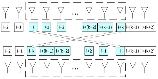
Figure 1.
Fireworks Explosion Strategy.
- (2)
- Discrete Fireworks Mutation Operation
The mutation method is defined as follows: After excluding the first and last positions, randomly select an integer number of 1 s from the remaining positions and change them to 0 s. During each mutation, to ensure the number of array elements remains unchanged, an equivalent number of 0 s at randomly selected positions must simultaneously be changed to 1 s.
- (3)
- Discrete Fireworks Mapping Strategy
To ensure that the solutions generated during the optimization process consistently satisfy the physical constraints and predefined requirements of the array structure, we designed a feasibility-repair based binary mapping rule. The core idea is to repair and enforce constraints on the binary vectors after each operator (e.g., explosion, mutation) generates a new solution, thereby guaranteeing feasibility. This rule primarily consists of the following aspects:
- Endpoint Element Constraint
The first and last elements of both the transmit and receive arrays must always remain active. This ensures maximal utilization of the effective aperture of the array and prevents aperture shrinkage caused by missing edge elements.
- b.
- ActiveElementCountConstraint
The number of active elements in the transmit and receive arrays must strictly equal the predefined target values Nt and Nr, respectively. This constraint ensures that the solutions do not deviate from the problem setup (e.g., too many or too few active elements).
- c.
- FeasibilityRepairMechanism
If the number of active elements exceeds the target value:
All active elements are identified, excluding the endpoints. From the remaining middle section, excess elements are randomly selected and deactivated until the target count is reached.
If the number of active elements is below the target value:
All inactive elements are identified. A number of elements equal to the deficit are activated (in sequential order) to restore the total to the target value.
This repair process guarantees that each solution strictly satisfies both the fixed number of active elements and the endpoint activation conditions.
- d.
- BinaryMappingConsistency
Unlike modulo operations commonly used in continuous-domain algorithms, this rule performs repairs directly in binary space. All operations are executed on 0/1 variables, inherently aligning with the discrete nature of the problem. This avoids the inconsistency of continuous mappings when applied to binary optimization problems.
- e.
- FeasibilityPreservation
After repair, every individual satisfies:
and
Through the application of this repair rule, solutions produced either from Sobol initialization or subsequent operator updates can be consistently adjusted into feasible array configurations that satisfy the structural constraints. This mechanism ensures that the fixed number of active elements and the endpoint activation conditions are maintained throughout the optimization process, thereby preserving feasibility without requiring additional external penalties.
3.3. Fusion of IFWA and SA Algorithms (IFWA-SA)
The IFWA possesses global search capabilities to explore broad solution spaces and escape local optima. To enhance convergence, this paper integrates IFWA with simulated annealing (SA), proposing the IFWA-SA algorithm. By incorporating SA’s probabilistic acceptance mechanism and temperature-dependent local search, the algorithm dynamically adjusts solution acceptance probabilities (prioritizing global exploration at high temperatures and local exploitation at low temperatures). Simultaneously, IFWA’s global search ensures exploration-exploitation balance, improving both search efficiency and solution quality in complex spaces.
The simulated annealing mechanism allows probabilistic acceptance of inferior solutions, enhancing the ability of the algorithm to escape local optima. Each firework generates new candidate solutions through explosion and mutation. The fitness function evaluates solution quality, with the quality difference between candidates defined as:
During each iteration of candidate solution generation, inferior solutions (ΔF > 0) are accepted with probability P(ΔF), determined by the quality difference ΔF and current temperature T. Superior solutions (ΔF ≤ 0) are automatically accepted. The acceptance probability is calculated as follows:
The probability of accepting a worse solution is controlled by the temperature decay in simulated annealing. As the algorithm proceeds iteratively, the temperature is gradually reduced and the decay strategy is as follows:
where is the current temperature and is the attenuation factor (usually taking values from 0.9 to 0.99).
3.4. Optimization Steps
Step 1: Generate the initial fireworks population using Equation (19).
Step 2: Calculate the fitness value of each individual in the initial population.
Step 3: Check if the termination condition is met. If satisfied, terminate the algorithm and output the optimized sparse array design; otherwise, proceed to Step 4.
Step 4: Enter the iterative loop. Calculate the number of sparks and the explosion radius of fireworks based on Equations (12) and (13). Generate sparks through the explosion strategy.
Step 5: Perform a mutation operation to generate mutated sparks.
Step 6: Apply the simulated annealing mechanism to control the acceptance probability of inferior solutions using temperature parameters, thereby avoiding local optima.
Step 7: Select the next-generation fireworks population via a roulette wheel strategy. Sparks with larger distances from others have higher selection probabilities. Return to Step 3.
The flowchart of the IFWA-SA algorithm is illustrated in Figure 2. In addition, the pseudo code of the proposed IFWA-SA algorithm is shown in Algorithm 1.
| Algorithm 1: IFWA-SA Algorithm |
| Input: Population size N, maximum evaluations Max_NFE, number of transmit/receive elements (Nt, Nr), explosion parameters M, A, mutation probability, simulated annealing parameters (Tstart, a). |
| Output: Optimized sparse array element positions X* |
| Generate initial fireworks population X using Sobol sequences; Repair to satisfy feasibility constraints (endpoint fixed, number of active elements = Nt, Nr); Evaluate fitness of each individual according to PSL criterion; |
| while evaluations < Max_NFE do |
| Compute number of sparks and explosion radius Equations (12) and (13); Generate sparks via discrete explosion strategy; Apply mutation operator to produce new sparks; Repair solutions to enforce feasibility constraints; For each new spark: Calculate ΔF relative to current solution; if ΔF ≤ 0 then Accept new solution; else Accept with probability P = exp(−ΔF/T); end Update temperature T = aT; Select next-generation population: Preserve best solution (elitism); Select remaining N − 1 individuals using distance-based roulette strategy Equations (17) and (18); end |
| Return the best solution X* with minimum PSL. |
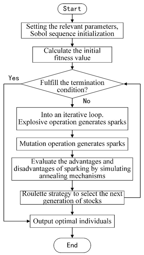
Figure 2.
Flowchart of the IFWA-SA algorithm.
4. Simulation Results and Discussions
To validate the effectiveness and feasibility of the proposed method, four simulation experiments were conducted. Case 1 carried out a comprehensive analysis of the three enhancement strategies integrated into the IFWA-SA algorithm. Case 2 compared the proposed algorithm with four benchmark methods—genetic algorithm (GA), particle swarm optimization (PSO), adaptive selection, and gray wolf optimizer (GWO)—to evaluate their performance in sparse array optimization. In both Case 1 and Case 2, the average spacing between the transmitting and receiving array elements was fixed at 2λ. Simulation Case 3 further demonstrated the generality of the algorithm by optimizing array layouts under different average element spacing constraints. Case 4 performed a robustness analysis from three distinct aspects. All simulations were executed using MATLAB 2018b on a computer equipped with an Intel i5-10210U CPU and 16 GB of RAM.
The algorithms included in the simulation are stochastic search-based swarm intelligence algorithms. Due to their inherent stochastic nature during the optimization process, Monte Carlo simulations were implemented to ensure statistically reliable performance analysis. The stability of the IFWA-SA algorithm was assessed through 50 independent runs, with the mean values of the outcomes calculated to ensure robustness.
To ensure a fair comparison among all algorithms, an equal computational budget was allocated for each trial. The optimization process was terminated once the maximum number of function evaluations (Max_NFEs = 10,000) was reached. This approach ensures that performance comparisons are based on equivalent computational cost rather than iteration count, which provides a more reliable metric for stochastic optimizers.
For population-based algorithms (GA, PSO, GWO, and IFWA-SA), the population size was set to 20. Therefore, these algorithms executed 500 iterations within the computational budget (10,000 evaluations/20 population size). In contrast, the SA algorithm, which processes one solution per iteration, was run for 10,000 iterations.
This study evaluates the antenna array optimization algorithm’s performance through radiation pattern synthesis and convergence curve analysis. The pattern synthesis in two-dimensional rectangular coordinate system can visualize the radiation energy distribution of antenna array. Convergence curves track the objective function value or solution trajectory during iterative optimization, enabling quantitative assessment of algorithmic performance and convergence behavior. A steeper slope in the convergence curve indicates rapid approach toward the optimal solution within fewer iterations, demonstrating higher optimization efficiency.
4.1. Simulation Case 1
A typical MIMO radar sparse array configuration was established with the following parameters: The transmit array consisted of Nt = 16 elements arranged on a grid with spacing of integer multiples of 0.5λ within the range . Similarly, the receive array comprised Nr = 8 elements positioned on a 0.5λ spaced grid over . To ensure a fair comparison, identical initial population sizes and parameter settings were adopted for both algorithms. A step-by-step simulation of the three enhancement strategies proposed in IFWA-SA was conducted to examine the effectiveness of each strategy.
4.1.1. Performance of Sobol Initialization
This subsection presents a detailed evaluation of the first enhancement—the Sobol sequence initialization strategy. To isolate and quantify its contribution to the overall algorithm performance, a comparative analysis was conducted between the original FWA and a modified version that incorporates solely the Sobol initialization (denoted as Sobol-FWA).
Upon reaching the maximum number of iterations , a comparison of the search accuracy between the original FWA and the Sobol–FWA was carried out. The resulting peak sidelobe levels (PSL) are summarized in Table 1. The beam pattern comparison in Figure 3 clearly demonstrates that the array optimized using FWA-Sobol achieves lower sidelobe levels. The comparative results clearly demonstrate the performance improvement achieved by the Sobol initialization strategy. Specifically, the Sobol–FWA yielded a lower average PSL of −22.40 dB, compared to −21.64 dB with the standard FWA, indicating a more consistent and superior optimization capability across multiple runs. Furthermore, the best-case PSL also improved from −24.24 dB to −24.33 dB.

Table 1.
Comparison of side lobe levels and iteration counts for the two algorithms.
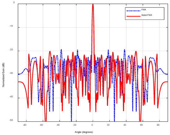
Figure 3.
Radiation patterns obtained by FWA and Sobol-FWA.
Figure 4 illustrates their respective iteration processes. By combining the iteration counts in Table 1 with Figure 4, we can obtain, the Sobol–FWA required fewer iterations to converge (852 vs. 937), confirming its faster convergence behavior under the same termination condition. These numerical results affirm that the use of Sobol sequences enhances both the solution quality and computational efficiency of the algorithm.
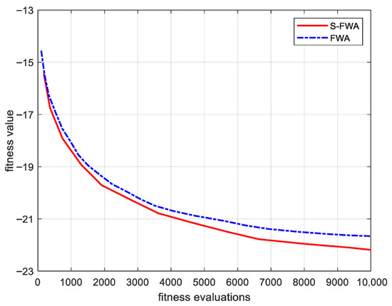
Figure 4.
Convergence curves of FWA and Sobol-FWA.
This demonstrates that Sobol sequences, with their high uniformity and ergodicity, can provide a set of higher-quality initial solutions for algorithms. This lays a stronger foundation for subsequent optimization processes and effectively avoids the risk of getting stuck in local optima due to poor random initialization.
4.1.2. Performance of Discretization Strategies
To evaluate the effectiveness of the proposed discrete improvement strategies for the Fireworks Algorithm (FWA), we conducted a comparative analysis between the standard continuous FWA and the discretized version (denoted as D-FWA).
Figure 5 compares the beam patterns synthesized by the original continuous FWA and the discrete-improved FWA (denoted as D-FWA). It can be observed that the D-FWA achieves significantly lower sidelobe levels and smoother radiation patterns. Meanwhile, the convergence curves in Figure 6 show that the D-FWA converges more steadily and avoids oscillations caused by infeasible solutions in the standard FWA.
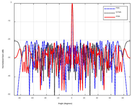
Figure 5.
Comparison of radiation patterns obtained by FWA, D-FWA, and the IFWA.
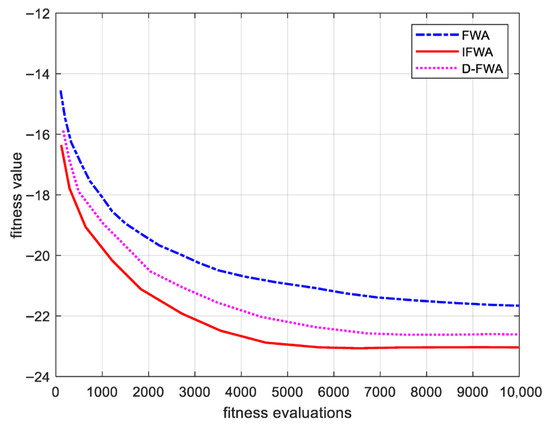
Figure 6.
Convergence curves of FWA, D-FWA, and the IFWA.
Quantitatively, the discrete strategy reduced the average PSL from −21.8602 dB to −22.6120 dB and improved the best-case PSL from −24.2306 dB to −24.6275 dB. Moreover, the number of iterations required for convergence decreased by approximately 11%, indicating an improvement in both efficiency and solution quality. These results confirm that tailoring the explosion, mutation, and mapping operators to the discrete binary domain is essential for sparse array optimization. The discretization not only ensures strict compliance with physical design constraints but also accelerates convergence by preventing wasted evaluations on invalid solutions.
Furthermore, when the Sobol initialization strategy is combined with the discretization mechanism (forming the IFWA), performance improves even more. As shown in Figure 5 and Figure 6, the IFWA achieves both faster convergence and lower sidelobe levels than either Sobol-FWA or D-FWA individually. Specifically, the average PSL further decreases to −23.5498 dB, and the best-case value approaches −24.87 dB. This demonstrates that Sobol initialization provides a uniformly distributed starting population that prevents poor initial clustering, while the discretization strategy guarantees feasibility and efficiency during subsequent optimization. Their combination produces a complementary effect: Sobol initialization strengthens global exploration at the beginning, and discretization ensures robust convergence later, thereby maximizing the optimization potential of the fireworks algorithm.
4.1.3. Performance of the SA Strategy Integration
The third enhancement strategy integrates simulated annealing (SA) into the IFWA framework to further refine local search capability. While the discrete FWA ensures global exploration, it may still stagnate around local optima in highly multimodal search spaces. By incorporating SA’s probabilistic acceptance rule, the algorithm gains the ability to accept slightly inferior solutions during high-temperature stages, thus escaping local traps and enabling deeper exploration of the solution landscape.
Figure 7 shows the beam mode synthesis results, where IFWA-SA achieves lower sidelobe levels compared to the standalone IFWA. As demonstrated by the convergence curves in Figure 8, IFWA-SA not only converges faster during early iterations but also continues to optimize in later stages, whereas IFWA risks getting stuck in local optima during the later phase.
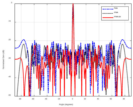
Figure 7.
Comparison of radiation patterns obtained by FWA, IFWA, and the IFWA-SA.
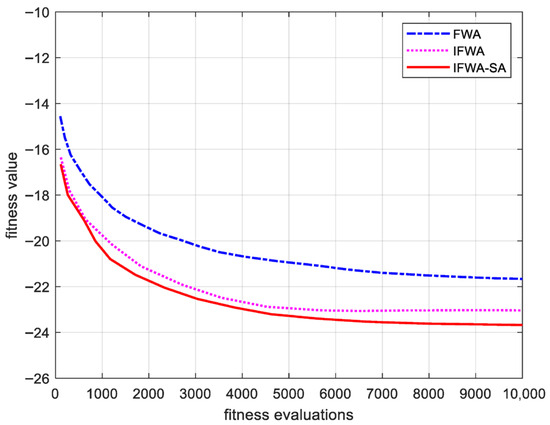
Figure 8.
Convergence curves of FWA, IFWA, and the IFWA-SA.
From the statistical results, the average PSL improved from −22.0391 dB (IFWA) to −23.8640 dB with IFWA-SA, while the best-case PSL reached −25.08 dB. Furthermore, the variance of the final solutions was significantly reduced, demonstrating enhanced robustness across independent Monte Carlo runs. This stability indicates that the annealing mechanism helps the algorithm maintain consistent performance despite the stochastic nature of metaheuristic optimization.
In summary, the SA integration complements the discrete FWA by striking a better balance between global exploration and local exploitation. The hybrid IFWA-SA not only yields superior optimization accuracy but also exhibits greater robustness and reliability, validating the necessity of this fusion strategy in sparse array synthesis.
4.2. Simulation Case 2
To further validate the generality and competitiveness of the proposed approach, the IFWA-SA algorithm was compared with four representative metaheuristic optimizers—Genetic Algorithm (GA), Particle Swarm Optimization (PSO), Simulated Annealing (SA), and gray wolf optimizer (GWO)—under identical computational budgets.
The selection of parameters for intelligent optimization algorithms significantly influences their performance and efficiency in solving optimization problems. Therefore, the parameter configuration strategies employed for each algorithm in this study are elaborated below. Rather than adopting fixed values directly from the literature, the key parameters of each algorithm were carefully tuned within recommended ranges through preliminary experimental tests. This ensures that each algorithm operates under a relatively reasonable configuration tailored to the specific problem domain, thereby mitigating comparison biases arising from improper parameter settings.
Genetic Algorithm (GA): The crossover probability Pc and mutation rate Pm were tested within the ranges {0.7, 0.75, 0.8} and {0.01, 0.05, 0.08}, respectively. After evaluation, Pc = 0.75 and Pm = 0.05 were selected, as they provided a satisfactory balance between convergence speed and stability.
Particle Swarm Optimization (PSO): The learning factors c1 and c2 were examined over the set {1.5, 2.0, 2.5}, along with a linearly decreasing inertia weight w from 0.9 to 0.4. The configuration c1 = c2 = 2.0 was ultimately adopted due to its most robust performance.
Simulated Annealing (SA): The initial temperature T0, attenuation factor α, and termination temperature were tuned within {500, 1000, 1500}, {0.9, 0.95, 0.98}, and {0.005, 0.01, 0.015}, respectively. The values T0 = 1000, α = 0.98, and a termination temperature of 0.01 were determined to be optimal.
Gray Wolf Optimizer (GWO): For this algorithm, the convergence coefficient a, which controls the exploration–exploitation balance, was investigated. Building upon the classic linear decrease strategy a:2→0, various final values afinal ∈ {0, 0.01, 0.1} were tested to assess their effect on local refinement accuracy. The influence of the social hierarchy coefficient A under conditions ∣A∣ > 1 and ∣A∣ < 1 was also compared. Results indicated that the canonical setting a:2→0, as recommended in the original literature, already delivered strong global exploration and local exploitation capabilities, with consistent and stable performance. Thus, this baseline configuration was retained.
IFWA-SA: The key parameters include the explosion amplitude constant, maximum number of sparks, and minimum number of sparks. Initial tests were conducted with the explosion constant in {35, 40, 45, 50, 55, 60}, which showed that a value of 50 achieved the best trade-off between convergence accuracy and stability. Similarly, the maximum and minimum number of sparks were determined to be 20 and 2, respectively.
Through the above parameter tuning process, all algorithms were compared under a unified computational budget, with each being moderately optimized within literature-recommended ranges. This approach minimizes bias due to parameter selection and ensures that the results more faithfully reflect the actual performance of each algorithm in the sparse array optimization problem.
Table 2 shows the key parameter settings of each algorithm. Table 3 lists the optimized array element positions generated by the five algorithms.

Table 2.
The relevant parameters of each algorithms.

Table 3.
Optimized element positions obtained by each algorithm.
Statistical results across 50 Monte Carlo trials are provided in Table 4. Several important observations can be drawn:

Table 4.
Comparison of sidelobe levels optimized by the five algorithms.
The primary metric for evaluation is the Peak Sidelobe Level (PSL). The proposed IFWA-SA algorithm achieves a mean PSL of −23.85 dB over 50 Monte Carlo trials, which is 1.27 dB to 3.82 dB lower than the mean values obtained by the other four algorithms. This significant improvement is consistent across all statistical measures: IFWA-SA also delivers the best minimum PSL (−25.07 dB), the best maximum PSL (−21.86 dB), and the best median PSL (−23.68 dB). Crucially, the exceptionally low standard deviation of 0.88 dB for IFWA-SA indicates superior robustness and stability, as it consistently produces high-quality solutions with minimal performance fluctuation across different runs. In contrast, while PSO and GWO can occasionally find very good solutions (evidenced by their low min PSL), their higher standard deviations (1.63 dB and 1.64 dB, respectively) signify less reliability.
The computational time, measured for a fixed budget of 10,000 function evaluations, presents a critical trade-off. The IFWA-SA algorithm requires an average of 226.68 s per run. This is higher than the computation time of GA (173.54 s) and GWO (217.51 s) but is notably lower than that of SA (289.06 s) and PSO (301.26 s). The increased time cost of IFWA-SA is attributed to its more complex hybrid structure, which involves generating multiple sparks and executing the simulated annealing acceptance criterion each iteration. However, this computational overhead is justified by the algorithm’s decisively superior performance. The significantly lower and more stable PSL values achieved by IFWA-SA imply that it offers a far better performance-to-computation ratio; achieving a comparable PSL with the other algorithms would likely require a much larger computational budget from them, if it is achievable at all.
These findings clearly demonstrate that the proposed IFWA-SA not only achieves the best sidelobe suppression but also delivers more reliable results across repeated runs.
The radiation patterns in Figure 9 provide a visual comparison of the synthesized arrays. From the global view in Figure 9a, IFWA-SA maintains the lowest sidelobe floor across the entire angular domain. The zoomed-in view in Figure 9b further highlights the mainlobe and adjacent sidelobe regions, showing that IFWA-SA achieves clean suppression of the sidelobe peaks without sacrificing mainlobe sharpness. This characteristic is particularly valuable in MIMO radar applications, where strong clutter or jamming signals may occur in unknown directions.
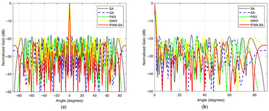
Figure 9.
Comparison of antenna array patterns optimized by different algorithms: (a) Global view, (b) zoomed-in view.
The convergence trajectories in Figure 10 and Figure 11 offer insights into the algorithmic dynamics. The average fitness curve of IFWA-SA (Figure 10) shows a rapid initial descent and stable convergence to a value far superior to the others, demonstrating its effective balance between global exploration and local exploitation. The GA and SA converge relatively slowly and become trapped at higher sidelobe levels (≈−22 dB), while PSO and GWO converge more quickly but display oscillatory behavior due to premature convergence.
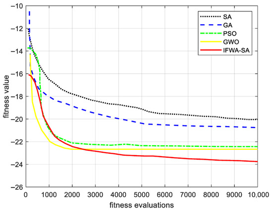
Figure 10.
Average fitness trajectory of the best individual over 50 trials.
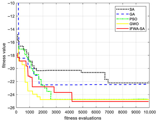
Figure 11.
The fitness trajectory of the global optimum solution.
Figure 11, depicting the trajectory of the global best solution found across all runs, shows that while IFWA-SA’s initial convergence rate is competitive, it continues to refine the solution beyond the point where other algorithms stagnate. This highlights the enhanced capability of the hybrid IFWA-SA strategy to escape local optima and navigate towards the global optimum, a direct benefit of combining the population-based search of IFWA with the probabilistic fine-tuning of SA.
4.3. Simulation Case 3
To demonstrate the universality of the proposed algorithm, the positions of the transmitter and receiver elements were optimized for different average inter-element spacings. The spacings ranged from 0 to 32λ for the transmitter and 0 to 16λ for the receiver. By varying the number of transmitter and receiver elements, different average spacings were obtained.
Table 5 shows the optimized positions of the array elements obtained using the IFWA-SA algorithm for different average inter-element spacings.

Table 5.
Optimized element positions.
As shown in Figure 12, (a)–(d) illustrates the array element configurations after optimization for systems with (8, 4), (12, 6), (16, 8), and (20, 10) transmitter and receiver elements, respectively.
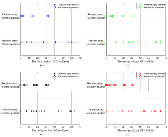
Figure 12.
Result diagram of optimized sensor locations for different average sensor spacing: (a) The number of array elements is (8, 4); (b) the number of array elements is (12, 6); (c) the number of array elements is (16, 8); (d) the number of array elements is (20, 10).
The results in Table 6 and Figure 13 clearly demonstrate a fundamental and expected trade-off in sparse array design: the achievable PSL performance is inversely correlated with the average inter-element spacing.

Table 6.
Performance of the IFWA-SA in 50 runs with different average array element spacing.
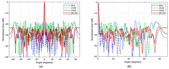
Figure 13.
Antenna array pattern synthesis results with different average array element spacing: (a) global view; (b) zoomed-in view.
As the array becomes sparser (i.e., the average spacing increases), the optimized PSL progressively increases (worsens). The system with the largest average spacing (8, 4 configuration, average spacing = 32λ/7 ≈ 4.57λ for transmit and 16λ/3 ≈ 5.33λ for receive) yields the highest mean PSL of −16.83 dB. This is because a sparser array has fewer degrees of freedom (fewer elements) to precisely shape the beam pattern and suppress sidelobes. The resulting aperture has larger gaps, which leads to higher grating lobes and increased average sidelobe levels, as clearly visible in the pattern for the (8, 4) configuration in Figure 12a.
Conversely, as the number of elements increases and the average spacing approaches the fundamental limit of λ/2 (i.e., the array becomes less sparse), the optimization algorithm has more control variables to work with. This allows for more effective suppression of sidelobes. The (20,10) configuration, with the smallest average spacing, achieves the best mean PSL of −24.99 dB, which is approximately 8 dB lower than that of the sparsest (8, 4) configuration. The patterns in Figure 13 show a visible and systematic improvement in sidelobe suppression as the number of elements increases.
The consistent inverse relationship between PSL and average spacing—observed across all four tested configurations—validates that the IFWA-SA algorithm correctly internalizes the underlying physics of array synthesis. More importantly, the results highlight the algorithm’s robustness and generality. It proficiently leverages additional elements to minimize PSL when they are available. Crucially, it also performs reliably under stringent sparsity constraints. Even in the most challenging (8, 4) case with average spacings significantly exceeding λ/2, the algorithm successfully synthesizes a layout that achieves a PSL of approximately −17 dB. This result constitutes a substantial improvement over any non-optimized or uniformly sparse layout, demonstrating the value of the optimization even in adverse conditions.
4.4. Discussion and Analysis
4.4.1. Mutual Coupling Analysis
The signal model and optimization process described earlier in this paper both assume ideal isolation between array elements. However, in actual array systems, electromagnetic mutual coupling effects between adjacent antenna elements alter the current distribution across each element. This can lead to pattern distortion and elevate peak side lobe levels (PSL), which is a critical consideration in array design. To evaluate the robustness of sparsely arranged arrays optimized by the IFWA-SA algorithm against this effect, this section employs a classical half-wave dipole mutual impedance model for quantitative analysis.
For two parallel half-wave dipoles placed side-by-side, the mutual impedance can be expressed as a function of their spacing dd normalized by the wavelength λ, i.e., d/λ. This model provides a reasonable approximation for estimating coupling effects in linear arrays. The mutual impedance between two parallel half-wave dipoles, as a function of the normalized spacing d/λ, can be obtained by solving the Hallen or Pocklington integral equations. This model serves as an effective theoretical tool for rapid estimation of mutual coupling in linear arrays. The self-impedance of an isolated half-wave dipole is approximately . The coupling strength can be quantitatively characterized by the following ratio:
In engineering practice, it is generally accepted that the effect of mutual coupling on the radiation pattern is negligible when κ < 0.1 (i.e., below −20 dB). The curve of the radiation impedance changing with the array element spacing is shown in Figure 14.
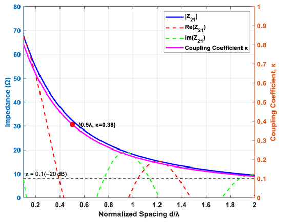
Figure 14.
Curve of the radiation impedance changing with the array element spacing.
The array configuration optimized by the IFWA-SA algorithm—specifically, the best-performing 16-transmit/8-receive array layout (element positions provided in Table 3)—was evaluated for mutual coupling effects. In this sparse array, the minimum center-to-center spacing between any two adjacent elements is = λ/2. Based on the mutual impedance model introduced above, the coupling coefficient at this critical distance is approximately κ ≈ 0.38. The most significant coupling occurs within tightly spaced element clusters in the transmit array, such as the elements located at positions 33, 34, and 35 (in units of λ/2) in the IFWA-SA-optimized result.
To quantify the impact of mutual coupling on radiation performance, the computed mutual impedance matrix was incorporated to perturb the ideal uniform current excitation. A Monte Carlo simulation with 100 independent trials was conducted to assess statistical variations. The results indicate that mutual coupling leads to an average degradation in the peak sidelobe level (PSL) of approximately 0.8 dB for the optimized array. In contrast, the mainlobe beamwidth remained stable and was not significantly affected.
Critically, the performance improvement attributable to the IFWA-SA algorithm itself—a notable PSL gain of 1–3 dB compared to algorithms such as GA and PSO, as shown in Table 4—substantially outweighs the degradation induced by mutual coupling. Moreover, in practical MIMO radar system implementations, additional techniques such as isolators, decoupling networks, or active impedance matching can be employed to further suppress coupling effects. In conclusion, the performance superiority of the sparse array layout synthesized by the proposed IFWA-SA algorithm exhibits strong robustness against inherent mutual coupling effects.
4.4.2. Array Gain Analysis
Array Gain (AG) is a key performance metric that measures an array’s ability to detect weak signals in noisy environments. It is defined as the ratio of the output signal-to-noise ratio () to the single-channel input signal-to-noise ratio (), expressed in decibels (dB). The exceptional coherent processing capability of the virtual array in a MIMO radar system is directly reflected in its array gain. To validate the effectiveness of the sparse array optimized by the IFWA-SA algorithm under noisy conditions, this section analyzes its array gain characteristics as a function of the input SNR.
For a MIMO radar system with uniform weighting operating in an isotropic noise environment, the ideal array gain AG_ideal is given by:
where = 16 is the number of transmitting elements and = 8 is the number of receiving elements. Substituting these values yields a theoretical maximum gain of .
The actual gain performance of the array was evaluated through Monte Carlo simulations. The desired signal was assumed to be a complex sinusoidal wave incident from the boresight direction (u = 0), and the background noise was modeled as additive white Gaussian noise (AWGN), independent and identically distributed across all receiving channels. For each given input SNR_in, the output SNR_out was computed over 100 independent trials, and the array gain was statistically evaluated as . The simulation employed the optimal sparse array layout obtained by the IFWA-SA algorithm (see Table 3 for element positions).
As supported by the results in Figure 15, the measured array gain closely agrees with the theoretical value of 21.07 dB for SNR_in ≥−20 dB, with a deviation of less than 0.4 dB. This indicates that under conventional SNR conditions, the optimized sparse array effectively leverages the advantages of the virtual aperture, achieving coherent signal integration while suppressing noise incoherently, thereby attaining performance consistent with theoretical expectations.
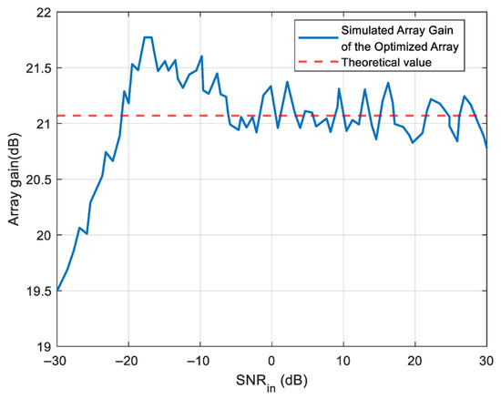
Figure 15.
Array gain versus input SNR for the optimized sparse array.
As SNR_in decreases below −20 dB, a slight attenuation in array gain is observed, which is consistent with statistical expectations. Under an extreme condition of SNR_in = −30 dB, the mean array gain is approximately 19.52 dB, representing a reduction of about 1.55 dB from the theoretical value. This phenomenon aligns with established statistical behavior, attributable to increased noise interference in the signal correlation process at low SNR levels.
4.4.3. Position Uncertainty Analysis
To assess the robustness of the sparse array layout optimized by the IFWA-SA algorithm against practical deployment uncertainties, a position uncertainty analysis was conducted. In real-world MIMO radar systems, factors such as installation errors, mechanical vibrations, and environmental disturbances may cause deviations of the actual element positions from their designed values, which can potentially degrade the array pattern performance.
The element positions were perturbed by applying random offsets to the ideal grid points. These offsets followed a Gaussian distribution with zero mean and a standard deviation of σ, ensuring that the vast majority of the positional errors fall within a quarter-wavelength (λ/4) range (which corresponds to σ = λ/12).
The beampatterns of the optimized array, with and without position perturbations, are compared in Figure 16. The results indicate that the average PSL of the nominal array is −23.85 dB, while the PSL degrades to approximately −22.95 dB under positional perturbations. To provide a statistically reliable assessment, 100 Monte Carlo trials were performed. The average PSL under perturbed conditions was −22.87 dB, with a standard deviation of 0.42 dB. This corresponds to an average performance degradation of about 0.98 dB.
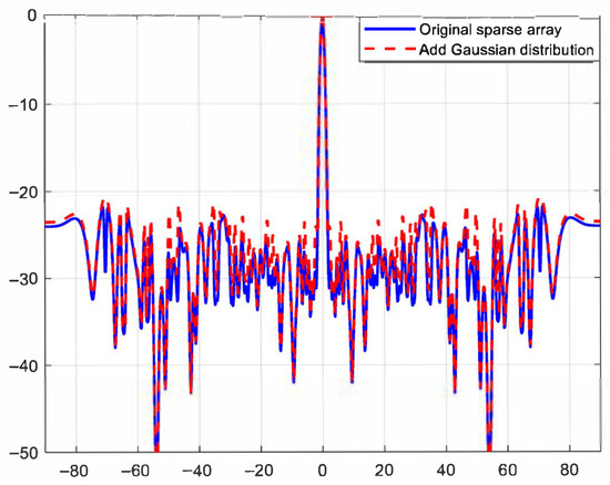
Figure 16.
Beampattern robustness of the optimized array under positional perturbations.
5. Conclusions and Prospects
In this work, an improved hybrid optimization algorithm (IFWA-SA) was proposed for sparse MIMO radar array synthesis. The method incorporated Sobol sequence initialization to enhance population uniformity, a discretized fireworks algorithm adapted to sparse array optimization, and a simulated annealing mechanism for probabilistic acceptance of inferior solutions.
Through simulations experiments, the effectiveness of the proposed approach was quantitatively verified. For the benchmark (16, 8) MIMO radar array configuration, a mean peak sidelobe level (PSL) of –23.85 dB was achieved, corresponding to a reduction of 1.27–3.82 dB compared with GA, PSO, SA, and GWO. The best-case PSL reached −25.07 dB, while the variance across 50 Monte Carlo trials was only 0.88 dB, confirming enhanced robustness. Although the average computational time of 226.68 s was slightly higher than GA and GWO, it was lower than SA and PSO, indicating a favorable trade-off between sidelobe suppression and computational cost. Compared with conventional optimization techniques, the proposed IFWA-SA exhibited stronger robustness and lower sidelobe levels, while the main limitation was the increased parameter sensitivity and slightly higher computational complexity. These results demonstrate that the IFWA-SA is an effective and practical tool for sparse array optimization in MIMO radar systems.
Future studies could explore integrating the IFWA-SA algorithm with composite convex optimization (CO) methods to establish a synergistic framework that leverages their complementary advantages. The IFWA-SA algorithm performs well in terms of convergence, but is highly parameter sensitive. Therefore, the introduction of an adaptive mechanism to reduce parameter dependence may help to compensate for the shortcomings of the method. In addition, future work will extend the optimization objective beyond sidelobe suppression to incorporate multiple performance metrics (e.g., mainlobe width, null depth, and gain ripple), thereby enabling a systematic analysis of trade-offs and achieving more comprehensive array performance. Furthermore, the effectiveness of the algorithm should be extended to other types of antenna arrays, such as optimizing elliptical antenna arrays and concentric rings.
Author Contributions
Conceptualization, L.D. and Y.L.; Methodology, L.D., J.Z. and Y.L.; Software, J.Z.; Writing – original draft, J.Z.; Supervision, L.D. and Y.L. All authors have read and agreed to the published version of the manuscript.
Funding
This research was supported by the Key Research and Development Program of Science and Technology of Jilin Province, China (Grant No. 20230203142SF).
Institutional Review Board Statement
Not applicable.
Informed Consent Statement
Not applicable.
Data Availability Statement
The original contributions presented in the study are included in the article, further inquiries can be directed to the corresponding author.
Acknowledgments
We would like to thank the reviewers for their comments and suggestions on the revision of this paper. We wouldlike to thank the Changchun Computing Center for providing technical support and powerful computing capacity during this study.
Conflicts of Interest
The authors declare no competing interests.
References
- Zhang, X.; Wang, X.; Huang, J.; So, H.C. Joint design of antenna selection and transmit linear array beamformer for integrated radar and communications. Digit. Signal Process. 2024, 144, 104281. [Google Scholar] [CrossRef]
- Shaikh, A.H.; Dang, X.; Ahmed, T.; Huang, D. New Transmit-Receive Array Configurations for the MIMO Radar With Enhanced Degrees of Freedom. IEEE Commun. Lett. 2020, 24, 1534–1538. [Google Scholar] [CrossRef]
- Tahcfulloh, S. Transmit-Receive Subarrays for MIMO Radar Array Antenna. Int. J. Adv. Sci. Eng. Inf. Technol. 2021, 11, 12–19. [Google Scholar] [CrossRef]
- Yin, J.; Ma, R.; Lin, M.; Zhou, S. Colocated MIMO Radar Waveform-Array Joint Optimization for Sparse Array. Sensors 2023, 23, 4375. [Google Scholar] [CrossRef] [PubMed]
- Liang, C.; Wang, Y.; Yang, Z.; Hu, X.; Pei, Q.; Gu, W.; Zhang, L. Cooperative Automotive Radars with Multi-Aperture Multiplexing MIMO Sparse Array Design. Electronics 2022, 11, 1198. [Google Scholar] [CrossRef]
- Shao, W.; Hu, J.; Ji, Y.; Pan, J.; Fang, G. Phase Error Correction in Sparse Linear MIMO Radar Based on the Equivalent Phase Center Principle. Remote Sens. 2024, 16, 3685. [Google Scholar] [CrossRef]
- BouDaher, E.; Hoorfar, A. Comparison of nature-inspired techniques in design optimization of non-uniformly spaced arrays in the presence of mutual coupling. Digit. Signal Process. 2020, 105, 102780. [Google Scholar] [CrossRef]
- Keizer, W.P.M.N. Linear Array Thinning Using Iterative FFT Techniques. IEEE Trans. Antennas Propag. 2008, 56, 2757–2760. [Google Scholar] [CrossRef]
- Prisco, G.; D’Urso, M. Maximally Sparse Arrays Via Sequential Convex Optimizations. IEEE Antennas Wirel. Propag. Lett. 2012, 11, 192–195. [Google Scholar] [CrossRef]
- Liu, Y.; Liu, Q.H.; Nie, Z. Reducing the Number of Elements in Multiple-Pattern Linear Arrays by the Extended Matrix Pencil Methods. IEEE Trans. Antennas Propag. 2014, 62, 652–660. [Google Scholar] [CrossRef]
- Zhang, W.; Li, L.; Li, F. Reducing the Number of Elements in Linear and Planar Antenna Arrays With Sparseness Constrained Optimization. IEEE Trans. Antennas Propag. 2011, 59, 3106–3111. [Google Scholar] [CrossRef]
- Boeringer, D.W.; Werner, D.H. Particle swarm optimization versus genetic algorithms for phased array synthesis. IEEE Trans. Antennas Propag. 2004, 52, 771–779. [Google Scholar] [CrossRef]
- Tian, Y.-B.; Qian, J. Improve the performance of a linear array by changing the spaces among array elements in terms of genetic algorithm. IEEE Trans. Antennas Propag. 2005, 53, 2226–2230. [Google Scholar] [CrossRef]
- Quevedo-Teruel, O.; Rajo-Iglesias, E. Ant Colony Optimization in Thinned Array Synthesis With Minimum Sidelobe Level. IEEE Antennas Wirel. Propag. Lett. 2006, 5, 349–352. [Google Scholar] [CrossRef]
- Karimkashi, S.; Kishk, A.A. Invasive Weed Optimization and its Features in Electromagnetics. IEEE Trans. Antennas Propag. 2010, 58, 1269–1278. [Google Scholar] [CrossRef]
- Goudos, S.K.; Siakavara, K.; Sahalos, J.N. Novel Spiral Antenna Design Using Artificial Bee Colony Optimization for UHF RFID Applications. IEEE Antennas Wirel. Propag. Lett. 2014, 13, 528–531. [Google Scholar] [CrossRef]
- Guney, K.; Onay, M. Optimal synthesis of linear antenna arrays using a harmony search algorithm. Expert Syst. Appl. 2011, 38, 15455–15462. [Google Scholar] [CrossRef]
- Al-Azza, A.A.; Al-Jodah, A.A.; Harackiewicz, F.J. Spider Monkey Optimization: A Novel Technique for Antenna Optimization. IEEE Antennas Wirel. Propag. Lett. 2016, 15, 1016–1019. [Google Scholar] [CrossRef]
- Saxena, P.; Kothari, A. Ant Lion Optimization algorithm to control side lobe level and null depths in linear antenna arrays. AEU Int. J. Electron. Commun. 2016, 70, 1339–1349. [Google Scholar] [CrossRef]
- Khodier, M. Comprehensive study of linear antenna array optimisation using the cuckoo search algorithm. IET Microw. Antennas Propag. 2019, 13, 1325–1333. [Google Scholar] [CrossRef]
- Wang, H.; Liu, C.; Wu, H.; Li, B.; Xie, X. Optimal Pattern Synthesis of Linear Array and Broadband Design of Whip Antenna Using Grasshopper Optimization Algorithm. Int. J. Antennas Propag. 2020, 2020, 5904018. [Google Scholar] [CrossRef]
- Wang, T.; Xia, K.-W.; Tang, H.-L.; Zhang, S.-W.; Sandrine, M. A Modified Wolf Pack Algorithm for Multiconstrained Sparse Linear Array Synthesis. Int. J. Antennas Propag. 2020, 2020, 9483971. [Google Scholar] [CrossRef]
- Owoola, E.O.; Xia, K.; Wang, T.; Umar, A.; Akindele, R.G. Pattern Synthesis of Uniform and Sparse Linear Antenna Array Using Mayfly Algorithm. IEEE Access 2021, 9, 77954–77975. [Google Scholar] [CrossRef]
- Durmus, A.; Kurban, R.; Karakose, E. A comparison of swarm-based optimization algorithms in linear antenna array synthesis. J. Comput. Electron. 2021, 20, 1520–1531. [Google Scholar] [CrossRef]
- Sun, L. Synthesis of linear thinned array based on improved binary brain storm optimization. AEU Int. J. Electron. Commun. 2023, 170, 154831. [Google Scholar] [CrossRef]
- Wang, X.; Yao, M.; Zhang, F. Teaching quality evaluation-based differential evolution and its application on synthesis of linear sparse arrays. Soft Comput. 2023, 27, 14735–14758. [Google Scholar] [CrossRef]
- Li, J.; Liu, Y.; Zhao, W.; Zhu, T. Application of Dandelion Optimization Algorithm in Pattern Synthesis of Linear Antenna Arrays. Mathematics 2024, 12, 1111. [Google Scholar] [CrossRef]
- Zhao, W.; Liu, Y.; Li, J.; Zhu, T.; Zhao, K.; Hu, K. A Wild Horse Optimization algorithm with chaotic inertia weights and its application in linear antenna array synthesis. PLoS ONE 2024, 19, e0304971. [Google Scholar] [CrossRef]
- Mou, J.; Wang, J.; Wang, Y.; Xiang, M.; Zhang, L. Pattern synthesis of linear antenna-array for high gain and low sidelobe level based on sand cat swarm optimization algorithm. J. Supercomput. 2024, 81, 318. [Google Scholar] [CrossRef]
- Murino, V.; Trucco, A.; Regazzoni, C.S. Synthesis of unequally spaced arrays by simulated annealing. IEEE Trans. Signal Process. 1996, 44, 119–122. [Google Scholar] [CrossRef]
- Li, J.; Tan, Y. A Comprehensive Review of the Fireworks Algorithm. ACM Comput. Surv. 2019, 52, 121. [Google Scholar] [CrossRef]
- Paulin, L.; Coeurjolly, D.; Iehl, J.-C.; Bonneel, N.; Keller, A.; Ostromoukhov, V. Cascaded Sobol’ sampling. ACM Trans. Graph. 2021, 40, 275. [Google Scholar] [CrossRef]
Disclaimer/Publisher’s Note: The statements, opinions and data contained in all publications are solely those of the individual author(s) and contributor(s) and not of MDPI and/or the editor(s). MDPI and/or the editor(s) disclaim responsibility for any injury to people or property resulting from any ideas, methods, instructions or products referred to in the content. |
© 2025 by the authors. Licensee MDPI, Basel, Switzerland. This article is an open access article distributed under the terms and conditions of the Creative Commons Attribution (CC BY) license (https://creativecommons.org/licenses/by/4.0/).