Article

Study of the Deformation and Instability Characteristics and Treatment of Gentle Tilt-Creeping Open-Pit Mine Slopes Containing Weak Interlayers

1
School of Engineering and Technology, China University of Geosciences (Beijing), Beijing 100083, China
2
Technology Innovation Center for Risk Prevention and Control of Major Project Geosafety, Ministry of Natural Resources, Beijing 100083, China
*
Author to whom correspondence should be addressed.
Appl. Sci. 2025, 15(18), 9960; https://doi.org/10.3390/app15189960
Submission received: 21 July 2025 / Revised: 28 August 2025 / Accepted: 3 September 2025 / Published: 11 September 2025
(This article belongs to the Special Issue A Geotechnical Study on Landslides: Challenges and Progresses)

Abstract

The creep failure of open-pit mine slopes with weak interlayers is one of the main types of slope instability in open-pit mines. The scientific and reasonable treatment of this type of landslide is of great significance for improving the quality of open-pit mining. In this study, we study a gently inclined and creep-type slope with weak interlayers in an open-pit mine in Inner Mongolia, China, and conduct systematic on-site engineering geological investigations, laboratory tests, and numerical simulations. The particle swarm optimization algorithm is introduced, and the creep model combining Burgers and Mohr–Coulomb is selected. Combined with triaxial compression creep test data, the creep model parameters of the weak interlayer soil are intelligently inverted. A typical profile is selected to analyze the stability of the slope. The results show that the creep of the weak interlayer is the main controlling factor for the deformation and failure of the slope. Under natural conditions, a clear continuous plastic zone appears at the front edge of the weak interlayer and the rear edge of the sliding body, resulting in slope instability and large deformation. Our results are in good agreement with the reality of engineering. Furthermore, we study the effectiveness of the local reinforcement treatment method for the weak interlayer. This study shows that local reinforcement of the weak interlayer is one of the most economical and effective means of preventing and controlling landslides. After reinforcement, the plastic zone of the slope only appears near the rear edge of the sliding body and the reinforced rock mass, with a poor connection, and the stability of the slope is good. Our results provide effective technical support for the treatment of this slope and offer a reference for the disaster prevention and mitigation of gently inclined and creep-type open-pit mine slopes with weak interlayers.

1. Introduction

Open-pit mining has the following advantages: sufficient resource utilization, high labor productivity, fast mineral construction, and low cost [1,2]; it is widely used for the extraction of shallow-buried solid minerals. Slopes formed by open-pit mining seriously threaten mining safety and have serious geological and environmental problems [3,4], which are widely present in coal mines [5,6], iron mines [7,8], and copper mines [9,10]. To analyze slope stability, scholars both in China and abroad have carried out a large number of laboratory tests, in situ monitoring, theoretical analysis, and numerical simulations [11,12], resulting in the formation of qualitative analysis methods such as the natural history analysis method, engineering geological analog method, and roping pole projection method, along with quantitative evaluation methods such as the limit equilibrium method, strength reduction method, and gravity loading method. These are all effective research and practical methods to be used for slope stability analysis [13,14]. Scholars have also conducted a large amount of research into bedding slopes containing weak interlayers. He et al. [15] conducted physical model experiments on layered slopes containing weak interlayers under different rainfall conditions, clarifying the deformation characteristics of rocky slopes containing weak interlayers and enriching the countermeasures of slope mitigation. Yang et al. [16] conducted indoor vibration table experiments to compare and study layered slopes containing uniform weak layers, and discontinuous interface seismic tests to reveal the effect of weak interlayers on the dynamic response and deformation of slope rock formations. Li et al. [17] focused on a Sichuan landslide containing a weak interlayer and performed a systematic field investigation, laboratory test, and a numerical simulation; they revealed the landslide mechanism, which provided new ideas and means for the mitigation of the slope along the layer. It cannot be ignored that the creep of rock and soil mass is also one of the main factors causing the deformation and failure of a slope with weak interlayers [18,19]. Yan [20], Liu [21], Ma [22], and Su [23] et al. studied the creep behavior of different mudstones, revealed the creep damage mechanism, and constructed a theoretical model suitable for elucidating the creep characteristics of mudstones. Chai [24], Zhang [25], Li [26], Wang [27], Xue [28] and others carried out systematic field investigations and monitoring, laboratory experiments, theoretical analysis, and numerical simulation studies to elucidate the characteristics of rock and soil creep, revealing the long-term deformation characteristics and failure mechanism of slopes with weak interlayers and providing effective scientific support for engineering mitigation. However, with the development of open-pit mining to deeper and larger areas, open-pit slopes face new scientific and technical challenges [29,30,31].
In this study, we used the slope of an open-pit coal mine in Inner Mongolia as an engineering example. A triaxial compressive creep test of the weak interlayer was carried out, the parameters of the creep model of the weak interlayer were intelligently inverted using the particle swarm optimization algorithm, and the influence of different suitability functions on the inversion results was compared. The typical profile of the pit slope was selected, an in situ scale numerical model was constructed, the long-term deformation and stability characteristics of the gently dipping, creep-slipping, and soft interlayer of the sedimentary mudstone slope were studied, and slope mitigation was realized via the method of local reinforcement of the weak interlayer. Our research results provide scientific support for the mitigation of this type of landslide.

2. Project Overview

The coalfield used as our research area is located in the Inner Mongolia Autonomous Region and is mined in open pits. Long-term coal mining means that a wide range of open-pit mines have been formed, with a maximum length of 5.81 km from east to west, a maximum width of 4.01 km from north to south, and an area of 22.38 km2. The maximum length of the bottom boundary is 4.93 km from east to west, the maximum width from north to south is 2.45 km, and the area is 11.13 km2. The maximum mining depth is 350 m. Under the influence of weak interlayers, the slope of the open pit is slippery, there are large-scale cracks on the ground, and the slope is not very stable (Figure 1), which threatens the safety of mining personnel and machinery and restricts mining developments.
The results of our field investigation show that the main strata in the mining area, from top to bottom, are loose deposits, cultivated soil, red clay, sandy gravel, and mudstone. The coal seam is mainly distributed in the mudstone, and the mudstone contains weak interbedding locally. The typical engineering geological profile of the study area is shown in Figure 2. Moreover, the on-site investigation revealed multiple layers of low-strength interlayers (Figure 3). The stratigraphy of the study area is described below:
Loose deposits: Rock formations are mainly distributed in the north and south dumps, with a thickness of up to 100 m, and the rest are distributed in the slope crest and surface layer of the pit slope around the secondary mining area and the pit, with a thickness of 1.0~22.0 m.
Cultivated soil: Brown-black humus, light yellow sand, light yellow ~ brownish gray silt, gray-white ~ yellow gravel, and a small amount of gray-brown ~ earth yellow ~ light yellow silty clay, silt, and other compositions. The soil is mainly distributed in the upper part of the pit, the east part, and the second mining area, with a continuous and uneven distribution, loose structure, and a thickness of 1.5–63.55 m. This soil collapses easily.
Red clay: Brown red ~ dark red clay, hand-kneaded with a slippery feeling. The composition of the clay is mainly minerals, with water absorption and expansion, and clay plasticity. After water loss and air-drying, it is hard, easy to crumble, and its formation stability is poor. This clay is mainly distributed in the work area, the east side, and the west side of the south row, and the second mining area of the pit, and some sections of the west part and the work area are missing. The thickness of the clay varies greatly, its distribution is discontinuous, and the local lens is distributed, with a thickness of 0.0~34.91 m (average thickness of 30.80 m).
Sandy gravel: Gray-white ~ gray-yellow sandy gravel layer, locally containing manganese nodules, poor sorting, medium roundness, mostly sub-angular ~ sub-round, general particle size of 0.2~3 cm, maximum particle size of 7 cm, containing a small amount of cohesive soil, loose, and with poor formation stability. This gravel is mainly distributed in the pit work area. Its thickness varies greatly, its distribution is discontinuous, and its local distribution is lens-like, with a thickness of 13.64~39.00 m (average thickness of 23.35 m).
Mudstone: Mainly gray-yellow, gray-black, gray-black, with a mud-like structure, layered structural mudstone, sandy mudstone, and black conglomerate-bearing mudstone, followed by light gray, gray-yellow, gray-brown siltstone, fine sandstone, and coarse sandstone. It has a small amount of yellow and gray coarse sandstone or conglomerate coarse-grained sandstone. It locally contains weak interlayers, which are fully weathered ~ strongly weathered mudstone, broken ~ extremely broken, and soft and muddy after saturation (Figure 3).
The groundwater in the study area mainly exists in loose rock pores and bedrock fissures, which can be divided into loose rock pore unconfined water and bedrock fissure confined water. As a result of years of coal mining, the work area has formed a groundwater runoff drainage system centered on the pit. Loose rock pore unconfined water is basically drained; it only exists in low-lying areas and is transformed into platform unconfined water, with only a small amount of water. Comprehensive analysis shows that the hydrogeological conditions in the study area are simple.

3. Creep Parameter Inversion and Model Construction of Weak Interlayer

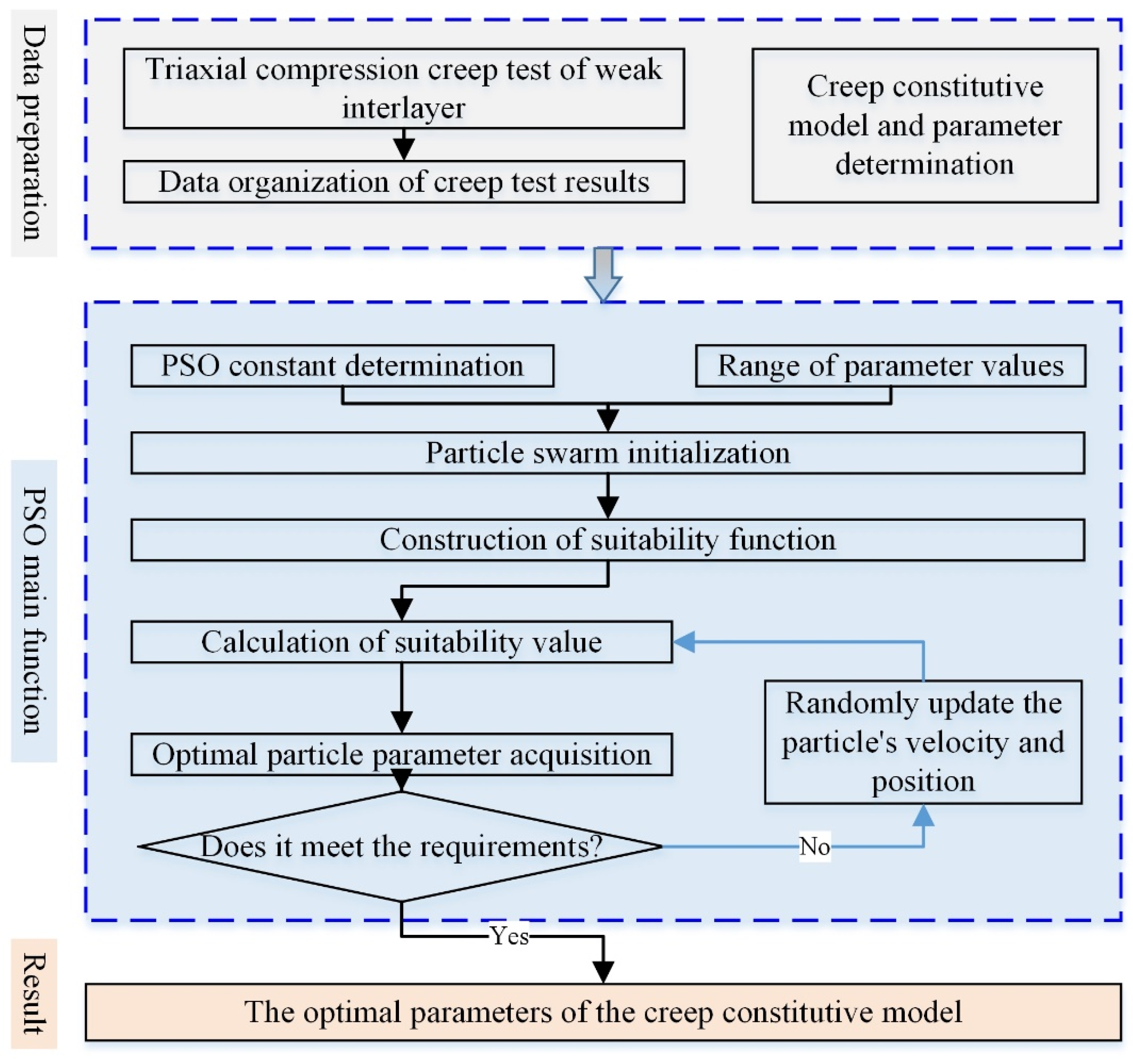
In 1995, inspired by the foraging behavior of birds, American social psychologist J. Kennedy and electrical engineer R. C. Eberhart proposed the particle swarm optimization algorithm (PSO) [32], which has the advantages of fast convergence and high accuracy, and it is widely used to solve optimal solution problems such as the inversion of the mechanical parameters of geotechnical materials [33,34]. In this study, a triaxial compressive creep test of the weak interlayer was carried out, and the particle swarm optimization algorithm was introduced to form the parameter inversion method of the weak interlayer creep model. This creep model, combined with the Burgers model and the Mohr–Coulomb yield criterion, combined with the Boltzmann linear superposition method, realized the theoretical construction of the multi-stage loading test curve of the triaxial compression creep test. Taking the strain difference between the experimental value and the theoretical value and the difference between the test value and the theoretical value of the normalized treatment strain as suitability functions, the inversion of soil creep parameters was carried out, the test results of creep models with different suitability degrees were compared, and the creep model parameters of the weak interlayer were obtained. Combined with the field investigation and engineering experience, the geometric model of typical sections was selected. The research methodology is shown in Figure 4.

3.1. Suitability Function Construction

The suitability function reflects the error between the theoretical and experimental values, which affects the accuracy of the inversion results. In this study, the Burgers–Mohr–Coulomb joint model was selected as the creep model. The creep model has the following characteristics: when the shear stress is less than the yield strength, the model shows Burgers creep model behavior, including attenuation creep and isokinetic creep stages; when the shear stress is equal to the yield strength, the strain increases rapidly, which is manifested as an accelerated creep stage. The schematic diagram of the creep model is shown in Figure 5, and Equation (1) is the one-dimensional expression equation. The strength parameters of the Mohr–Coulomb strength criterion are calculated using the strength values obtained from the laboratory creep test, and the parameters of the Burgers creep model are obtained by inverting the creep curve. In this study, two suitability functions are selected to compare and study their effects on the inversion results: 1. the absolute sum of the difference between the theoretical value and experimental value of the creep strain is the suitability function, as shown in Equation (2); 2. the absolute sum of the difference between the theoretical value and experimental value of the normalized creep strain is the suitability function, as shown in Equation (3). The theoretical value of the strain is calculated using the Boltzmann linear superposition method.
ε 1 = σ 0 E 1 + σ 0 η 1 t + σ 0 E 2 1 e E 2 η 2 t       σ 0 < σ s ε 1                                                                                               σ 0 = σ s
where ε 1 is the axial strain;
  • σ 0 is the uniaxial stress;
  • E 1 , E 2 is Young’s modulus;
  • η 1 , η 2 is the viscosity coefficient;
  • t is the creep time;
  • σ s is the yield strength determined using the Mohr–Coulomb strength criterion.
Figure 5. Schematic diagram of the Burgers–Mohr–Coulomb joint model.
Applsci 15 09960 g005
φ = t = 0 T ε t ε e
φ = t = 0 T ( ε t ε e ) / ε e
where φ is the objective function of the suitability degree;
  • T is the test time in the whole creep test;
  • ε t is the strain theoretical value at time t;
  • ε e is the strain experimental data at time t.

3.2. Creep Model Parameters Inversion

Representative specimens of weak interlayer soil were obtained on site (Figure 6a), and standard soil specimens with a diameter of 38 mm and height of 80 mm were prepared. Based on the geotechnical test manual and relevant literature, the soil specimens were consolidated with 50 kPa, 100 kPa, and 200 kPa, respectively, with a loading rate of 10 kPa/min; the triaxial compression creep test was carried out after the consolidation was completed, and the axial loading rate was 10 kPa/min. The loading scheme under different confining stress is shown in Table 1, and the test is shown in Figure 6.
Figure 7 shows the strain curves and suitability value variation curves of three soil samples with different suitability functions at multi-level loads. The suitability values calculated using different suitability functions decrease rapidly with the increase in the calculation step and gradually tend to be stable values, with good convergence, indicating that the method has a good effect on inverting creep model parameters (Figure 7c,d). However, there are obvious differences in the creep curve results of different specimens inverted with different suitability functions. Based on the suitability function defined via the strain difference, the theoretical values of the creep curves of the three specimens are in good consistency with the test values, especially when the stress difference is high and the strain value is large. Based on the suitability function defined by the normalized strain difference, the theoretical value and experimental value of the creep curves of the three samples have good consistency when the stress difference is low and the strain value is small, and there is a deviation between the two when the stress difference is large and the strain value is large.
In summary, the results of the suitability function inversion defined by the strain difference are used as the creep model parameters, and the strength characteristics are considered. The Burgers–Mohr–Coulomb joint model parameters are shown in Table 2.

3.3. Typical Profile Model Construction

The finite difference numerical simulation software FLAC3D (Version 5.0) was used. A typical slope profile was selected, and a numerical calculation model was established, as shown in Figure 8. The model measures 3043 m long and 513 m high and consists of 685,200 units and 720,048 nodes. The stratigraphic lithology is loose deposits, cultivated soil, clay, gravel, and mudstone from top to bottom. Among them, the mudstone is locally interbedded with a thickness of 0.5–1.0 m and a thick, weak interlayer. The elastoplastic constitutive model of the Mohr–Coulomb strength criterion is used for loose deposits, cultivated soils, clays, gravel, and mudstones; that is, the creep behavior of these rock and soil layers is not considered, and only their loads are considered. Derived from the results of the laboratory tests in the survey report, the physical and mechanical parameters are shown in Table 3. The Burgers–Mohr–Coulomb joint model was used for the weak interlayer, with a density of 1860 kg/m3. The model parameters are shown in Table 2. Moreover, the treatment method for the localized solidification of the weak interlayers was explored.
The bottom surface of the model is constrained by vertical and horizontal displacement, which is a fixed boundary; the normal deformation is constrained around it, and the ground surface is a free surface. The load is the self-weight of the rock and soil mass. In order to accurately evaluate the deformation and failure behavior of the slope, combined with the characteristics of slope deformation, two vertical displacement monitoring points were arranged on the ground surface, numbered 1# and 2#, respectively. Three horizontal displacement monitoring points were established, numbered 3#, 4#, and 5#, respectively. The location of the monitoring points is shown in Figure 8.

4. Results

The creep of the weak interlayer is the main controlling factor of the gentle tilt-creeping slope. Considering the creep behavior of the weak interlayer, this study analyzes the long-term deformation behavior of the slope, including the settlement deformation and horizontal slip deformation of the slope, as well as the distribution of the plastic zone and the plastic deformation of the slope, which provides a scientific basis and support for the mitigation of this type of slope.

4.1. Slope Deformation

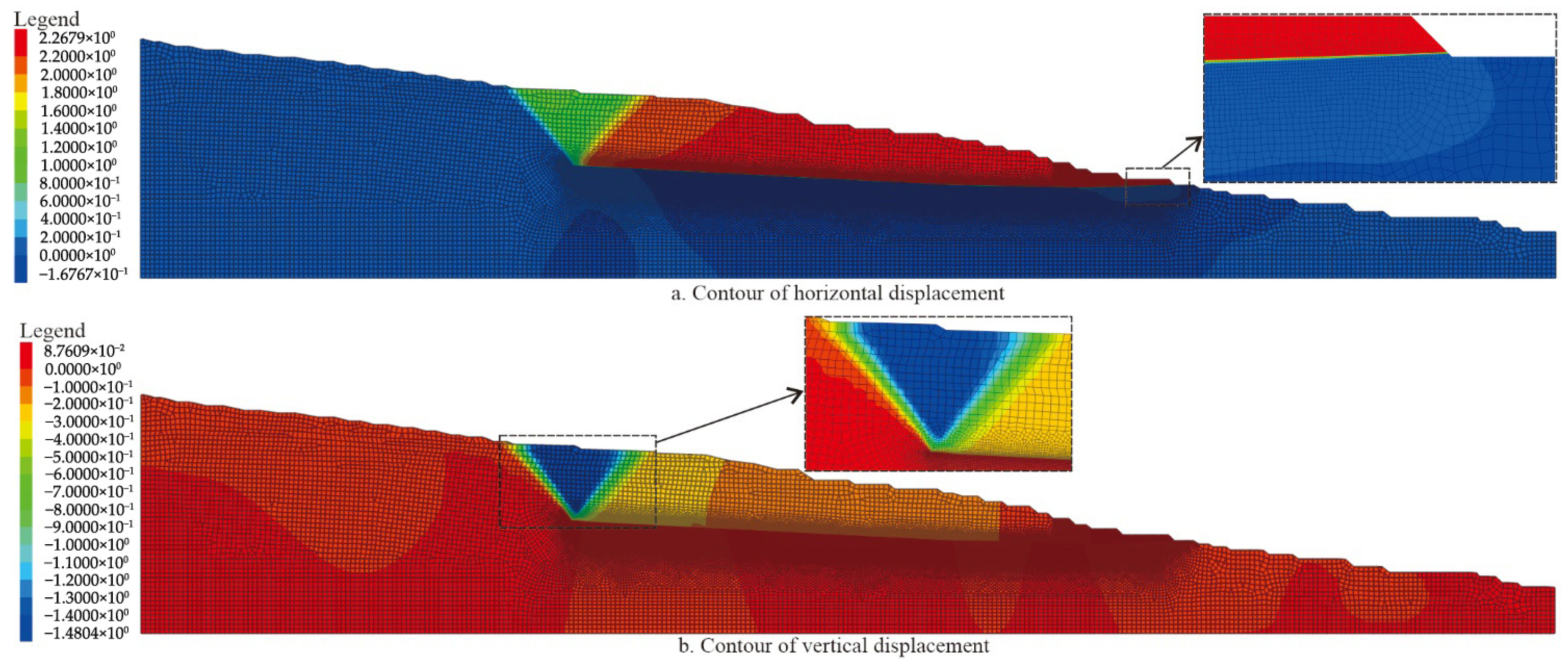
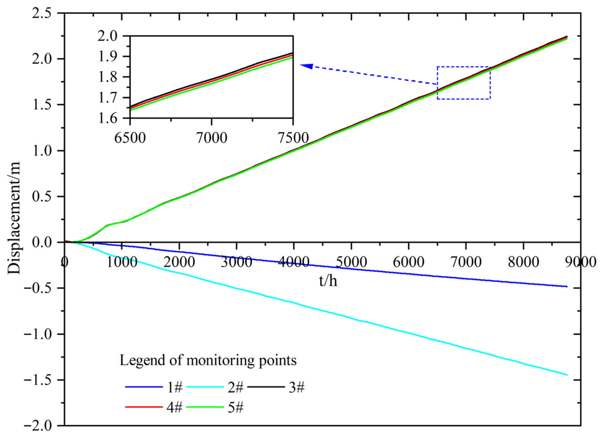
Figure 9 shows the vertical and horizontal displacement contours of the slope after 1 year (8760 h) of slope deformation. Figure 10 shows the displacement curve of the five monitoring points over time. We can see from this figure that the rock and soil mass above the weak interlayer is the main sliding body. The horizontal displacement and vertical displacement of the slope gradually increase, and they are manifested as the constant velocity creep stage. The sliding body has mainly horizontal displacement, and the trailing edge of the sliding body has mainly vertical displacement. In the horizontal direction, the slope slowly slides along the weak interlayer, and the deformation values are basically equal, with a maximum value of 2.27 m after 1 year of free deformation. In the vertical direction, the displacement mainly occurs at the position of the trailing edge of the connection between the sliding body and the sliding bed, and the settlement area is wedge-shaped. The maximum settlement value is about 1.48 m. Therefore, the range and deformation of the sliding body are mainly controlled by the weak interlayer.

4.2. Distribution of Plastic Zone and Plastic Deformation

Figure 11 shows the distribution of plastic zones and the incremental contours of the plastic deformation of the slope after 1 year of free deformation. It can be seen from the figure that the plastic zone is mainly distributed at the trailing edge of the sliding body and the leading edge of the weak interlayer, and the weak interlayer has a large plastic deformation. The maximum value of the strain increment is 0.85. The plastic zone at the trailing edge of the sliding body shows that the rear end of the weak interlayer expands and penetrates to the ground in a direction close to ±45° to form a wedge-shaped body, which is consistent with the deformation law of the slope. Therefore, the deformation of the slope is mainly caused by the creep failure of the weak interlayer and gradually expands to the trailing edge to form a penetrating plastic failure zone at the trailing edge of the sliding body.

4.3. Treatment of Localized Solidification of the Weak Interlayers

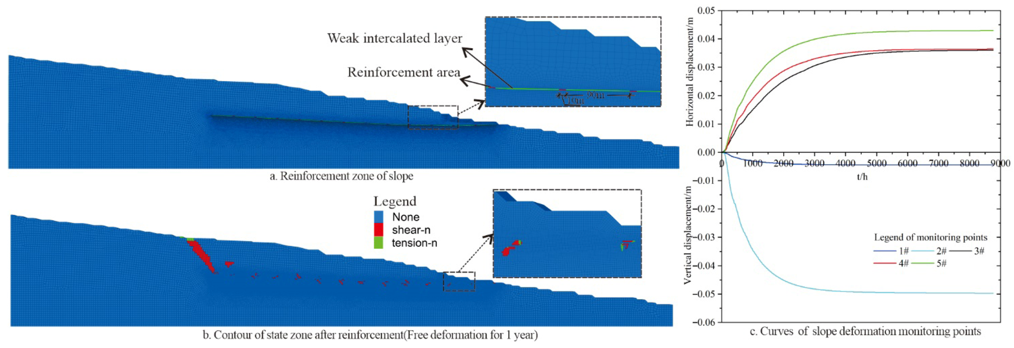
The creep of the weak interlayer is the main controlling factor of the deformation and failure of the landslide. Considering the cost and engineering characteristics, this study initially proposed a scheme for local reinforcement of the weak interlayer to treat the slope (for every 100 m of weak stratum, reinforce 10 m, Figure 12a). By drilling and stirring, the cement and the weak interlayer are mixed to provide the strength and modulus of the weak interlayer, reducing or even eliminating its significant creep behavior. Combined with engineering experience, the physical and mechanical parameters of the weak interlayer soil after reinforcement are shown in Table 4. Figure 12 shows the slope reinforcement scheme, as well as the distribution of plastic zones and the deformation of monitoring points after reinforcement for 1 year. It can be seen from the figure that after local reinforcement, the slope deformation can be effectively controlled, and the maximum values of the settlement deformation of the trailing edge and the horizontal deformation of the sliding body are 4.95 cm and 4.25 cm, respectively, after 1 year of free deformation.

5. Discussion

In this paper, we intelligently inverted the parameters of the soil creep model using the particle swarm optimization algorithm, solving the problem of significant differences in creep parameters at different stress levels. It achieved the averaging of creep model parameters throughout the creep curve, demonstrating excellent convergence efficiency and accuracy [35]. Moreover, it compared the effects of two fitness functions on the parameter inversion results. Using the absolute value of strain as the fitness function (Equation (2)), the inversion results had better suitability at the large strain part of the creep curve; using the normalized processed strain difference as the fitness function (Equation (3)), the inversion results had better suitability at the small strain part of the creep curve. Considering the calculation of slope deformation in this project, the fitness function selected was Equation (2), and the calculation results had good consistency with the actual engineering.
For the gently inclined and creeping-type open-pit slopes with weak interlayers, the slope treatment methods such as anti-slide piles, anchor rods, and large-scale slope cutting have problems like complex construction processes and significant disturbance to the on-site construction, which restrict their application in the slope treatment of open-pit mines [36,37]. This study, based on specific engineering cases, conducted numerical simulation research, revealed the sliding mechanism, and proposed a treatment scheme of local reinforcement for the weak interlayers, which can effectively control the long-term deformation of the slope and has the characteristics of easy construction and low cost, providing an effective reference for the prevention and control of such types of landslides and related projects [38].

6. Conclusions

Combined with a field investigation, indoor test, and numerical simulation, the creep model parameters of the weak interlayer were intelligently obtained, and the deformation and failure characteristics were analyzed. The main conclusions of this study are as follows:
(1)
The creep parameters of the weak interlayer soil are a bulk modulus K of 7.35 MPa, shear modulus G1 of 81.20 MPa, shear modulus G2 of 1.02 MPa, viscosity coefficient η1 of 50.36 MPa∙h, viscosity coefficient η2 of 644.65 MPa∙h, and cohesion c of 21.34 kPa, and the internal friction angle is 9.02°.
(2)
The deformation and failure of this slope are mainly controlled by the weak interlayer, and the sliding body is mainly the rock and soil body above the interlayer. The deformation of the sliding body is mainly the overall horizontal deformation, and the maximum horizontal displacement after 1 year of free deformation reaches 2.27 m. The trailing edge of the sliding body forms a settlement wedge, and the maximum vertical displacement reaches 1.48 m after 1 year. The leading edge of the sliding belt and the trailing edge of the sliding body produce a penetrating plastic zone.
(3)
Local reinforcement of the weak interlayer can effectively control slope deformation. Using the reinforcement scheme of local cement and interlayer soil mixing, the maximum free horizontal deformation and vertical deformation in 1 year are 4.25 cm and 4.95 cm, respectively, and the plastic zone is mainly distributed near the trailing edge of the sliding body and the reinforced soil; it is only partially penetrated.

Author Contributions

Conceptualization, X.W. and H.W.; methodology, X.W. and H.W.; validation, X.W., G.W. and M.W.; investigation, X.W. and G.W.; writing—original draft preparation, X.W. and H.W.; writing—review and editing, X.W. and M.W. All authors have read and agreed to the published version of the manuscript.

Funding

This research received no external funding.

Data Availability Statement

No new data were created.

Conflicts of Interest

The authors declare no conflicts of interest.

References

  1. Ding, X.; Ao, Z.; Zhou, W.; Qin, H.; Yang, Z.; An, W.; Li, X.; Liu, H. Geopolymer-based modification of blasting sealing materials and optimization of blasting block size in coal seams of open pit mines. Int. J. Min. Sci. Technol. 2023, 33, 1551–1562. [Google Scholar] [CrossRef]
  2. Yan, J.; Xing, X.; Li, Z.; Ni, W.; Zhao, L.; Zhu, C.; He, Y. Development of a DFN-based probabilistic block theory approach for bench face angle design in open pit mining. J. Rock Mech. Geotech. Eng. 2024, 16, 3047–3062. [Google Scholar] [CrossRef]
  3. Tao, Y.; Zhang, R.; Du, H. Failure Prediction of Open-Pit Mine Landslides Containing Complex Geological Structures Using the Inverse Velocity Method. Water 2024, 16, 430. [Google Scholar] [CrossRef]
  4. Raza, I.; Ullah, H.; Ehsan, M.I.; Khalid, P.; Iqbal, M.Z.; Rasheed, S. An integrated geophysical and geotechnical solutions for assessing slope instability challenges in open-pit mining: Safeguarding mining operations. Bull. Eng. Geol. Environ. 2025, 84, 83. [Google Scholar] [CrossRef]
  5. Li, G.; Hu, Z.; Wang, D.; Wang, L.; Wang, Y.; Zhao, L.; Jia, H.; Fang, K. Instability mechanisms of slope in open-pit coal mines: From physical and numerical modeling. Int. J. Min. Sci. Technol. 2024, 34, 1509–1528. [Google Scholar] [CrossRef]
  6. Li, Z.; Zhao, Y.; Ren, H.; He, T.; Sun, Y. A Novel Approach to Automatically Identify Open-Pit Coal Mining Dynamics Based on Temporal Satellite Images. Remote Sens. 2025, 17, 1029. [Google Scholar] [CrossRef]
  7. Rezaei, M.; Mousavi, S.Z.S.; Esmaeili, K. Combination of Monte Carlo Simulation and Bishop Technique for the Slope Stability Analysis of the Gol-E-Gohar Iron Open Pit Mine. J. Min. Environ. 2025, 16, 613–632. [Google Scholar]
  8. Wang, C.; Min, H.; Zhu, T.; Wang, H.; Qin, W.; Zhang, G. Failure mechanism and stability analysis of the landslide: A case study for open pit iron mine in Xichang, Sichuan, China. Nat. Hazards 2022, 116, 663–691. [Google Scholar] [CrossRef]
  9. Lashgari, M.; Ozturk, C.A. Slope failure and stability investigations for an open pit copper mine in Turkey. Environ. Earth Sci. 2022, 81, 5. [Google Scholar] [CrossRef]
  10. Wang, F.; Ren, Q.; Jiang, X.; Niu, J.; Chen, B. Engineering geology and mechanism of multiple landslides in a large open-pit mine: The case of the Copper Mine in Qinghai Province, China. Bull. Eng. Geol. Environ. 2023, 82, 147. [Google Scholar] [CrossRef]
  11. Perumalla, R.; Kumar, R.S.; Govindaraj, M. Review of Slope Stability Analysis under Drawdown Conditions for Mine Slopes. Disaster Adv. 2025, 18, 222–227. [Google Scholar] [CrossRef]
  12. Zheng, H.; Jiang, P. The optimal control problem for stability analysis of general slopes. Eng. Geol. 2025, 352, 108089. [Google Scholar] [CrossRef]
  13. Ma, X.; Tao, Y.; Lu, M.; Sharma, A.; Zhang, J. Reliability analysis of soil slopes stabilized with piles under rainfall. J. Rock Mech. Geotech. 2025; in press. [Google Scholar] [CrossRef]
  14. Park, D. Stability analysis of earth slopes with counterweight fill: Kinematic limit analysis. Eng. Geol. 2025, 351, 108027. [Google Scholar] [CrossRef]
  15. He, Z.; Wang, B. Instability Process Model Test for Bedding Rock Slope with Weak Interlayer under Different Rainfall Conditions. Adv. Civ. Eng. 2018, 2018 Pt 2, 8201031. [Google Scholar] [CrossRef]
  16. Yang, H.; Pei, X.; Cui, S.; He, Z.; Lei, J. Effects of weak interlayers on seismic performance of bedding slopes based on shaking table tests. J. Rock Mech. Geotech. Eng. 2025; in press. [Google Scholar] [CrossRef]
  17. Li, J.; Hu, B.; Sheng, J.; Zhang, Z. Failure mechanism and treatment of mine landslide with gently-inclined weak interlayer: A case study of Laoyingzui landslide in Emei, Sichuan, China. Geomech. Geophys. Geo-Energy Geo-Resour. 2024, 10, 61. [Google Scholar] [CrossRef]
  18. Bao, M.; Chen, Z.; Nian, G.; Zhang, L.; Zhu, T. Study on creep properties of weak layer rock of slope under damage coupling. Bull. Eng. Geol. Environ. 2024, 83, 154. [Google Scholar] [CrossRef]
  19. Zhang, F.; Yang, T.; Li, S. Investigation on stability of large bedding slope affected by weak interlayer creep deformation. Mech. Time-Depend. Mater. 2023, 27, 227–250. [Google Scholar] [CrossRef]
  20. Yan, H.; Yu, F.; Zhu, C.; Yuan, J.; Wang, Q.; Wu, J. A new swelling—Creep model for red-bed mudstone and its application. Front. Earth Sci. 2025, 13, 1577262. [Google Scholar] [CrossRef]
  21. Liu, F.; Chen, W.; Yang, Z.; Deng, W.; Li, H.; Yang, T. Landslide Characteristics and Stability Control of Bedding Rock Slope: A Case Study in the Sijiaying Open-Pit Mine. Min. Metall. Explor. 2024, 41, 3007–3022. [Google Scholar] [CrossRef]
  22. Ma, Z.; Liu, W.; Xu, H.; Huo, Y.; Wang, Y.; Li, S. Damage creep model and application for sandy mudstone considering the effect of immersion deterioration. J. Mech. 2024, 40, 325–335. [Google Scholar] [CrossRef]
  23. Su, Y.; Cai, G.; Yin, F.; Shan, Y.; Wang, H. Investigation of the creep behavior and time-dependent constitutive model of red-stratum mudstone fill material in high-fill subgrade. Constr. Build. Mater. 2025, 458, 139560. [Google Scholar] [CrossRef]
  24. Chai, B.; Yin, K.; Du, J.; Xiao, L. Correlation between incompetent beds and slope deformation at Badong town in the Three Gorges reservoir, China. Environ. Earth Sci. 2012, 69, 209–223. [Google Scholar] [CrossRef]
  25. Zhang, S.-L.; Zhu, Z.-H.; Qi, S.-C.; Hu, Y.-X.; Du, Q.; Zhou, J.-W. Deformation process and mechanism analyses for a planar sliding in the Mayanpo massive bedding rock slope at the Xiangjiaba Hydropower Station. Landslides 2018, 15, 2061–2073. [Google Scholar] [CrossRef]
  26. Li, J.; Hu, B.; Sheng, J.; Huang, L. A Fractional-Order Creep-Damage Model for Carbonaceous Shale Describing Coupled Damage Caused by Rainfall and Blasting. Fractal Fract. 2024, 8, 459. [Google Scholar] [CrossRef]
  27. Wang, Z.; Hu, B.; Li, J.; Chen, K.; Zhong, Z.; Zhang, X. Analysis of dynamic disturbance and multistage shear creep damage evolution law of the weak intercalated layers in slope under the influence of coupled damage effect. Int. J. Damage Mech. 2024, 34, 236–269. [Google Scholar] [CrossRef]
  28. Xue, F.; Hu, B.; Zhong, Z.X.; Zhang, H.; Li, H. Study on shear creep characteristics of carbonaceous mud shale at different moisture contents under temperature cycling. Water 2025, 17, 567. [Google Scholar] [CrossRef]
  29. Han, G.; Zhang, C.; Singh, H.K.; Liu, R.; Chen, G.; Huang, S.; Zhou, H.; Zhang, Y. Characterizing large-scale weak interlayer shear zones using conditional random field theory. J. Rock Mech. Geotech. Eng. 2023, 15, 2611–2625. [Google Scholar] [CrossRef]
  30. Liu, D.; Shan, R.L.; Wang, H.; Li, Z.; Tong, X.; Zhao, Y.; Han, T.Y.; Zhao, X.P.; Li, Y.Z.; Bai, H.B.; et al. Study on triaxial creep mechanical properties and creep model of sandy mudstone with initial radial depth damage. Constr. Build. Mater. 2025, 483, 141772. [Google Scholar] [CrossRef]
  31. Liu, G.; Lei, J.; Guo, Z.; Chai, S.; Ren, C. Light weight obstacle detection for unmanned mining trucks in open-pit mines. Sci. Rep. 2025, 15, 9028. [Google Scholar]
  32. Kennedy, J.; Eberhart, R. Particle Swarm Optimization. In Proceedings of ICNN’95—International Conference on Neural Networks; IEEE: New York, NY, USA, 1995; Volume 4, pp. 1941–1948. [Google Scholar]
  33. Gan, L.; Shen, X.; Zhang, H. New deformation back analysis method for the creep model parameters using finite element nonlinear method. Clust. Comput. 2017, 20, 3225–3236. [Google Scholar] [CrossRef]
  34. Wang, H.; Zhang, B.; Yu, X.; Xu, N.; Ye, J. Long-term stability and deformation behaviour of anhydrite mine-out for crude oil storage. Rock Mech. Rock Eng. 2020, 53, 1719–1735. [Google Scholar] [CrossRef]
  35. Aydan, Ö.; Ito, T.; Özcan, N.T.; Özkan, İ.; Rassouli, F. Impression creep tests as index creep testing technique in rock mechanics and rock engineering. Rock Mech. Rock Eng. 2024, 1–26. [Google Scholar] [CrossRef]
  36. Jose, D.; Kolathayar, S.; Nayak, S. 3D finite element analysis of anti-slide pile performance for slope stabilization. Geotech. Geol. Eng. 2025, 43, 74. [Google Scholar] [CrossRef]
  37. Han, C.; Zu, F.; Du, C.; Shi, L. Analysis of excavation stability and reinforcement treatment of the cutting slope under the influence of old goaf. Appl. Sci. 2022, 12, 8698. [Google Scholar] [CrossRef]
  38. Volanis, G.; Galanakis, D.; Bolanakis, N.; Maravelakis, E.; Borg, R.P.; Stavroulakis, G.E. Modelling and Stability Assessment of the Rock Cliffs and Xrobb l-Ġħaġin Neolithic Structure in Malta. Heritage 2024, 7, 2944–2958. [Google Scholar] [CrossRef]
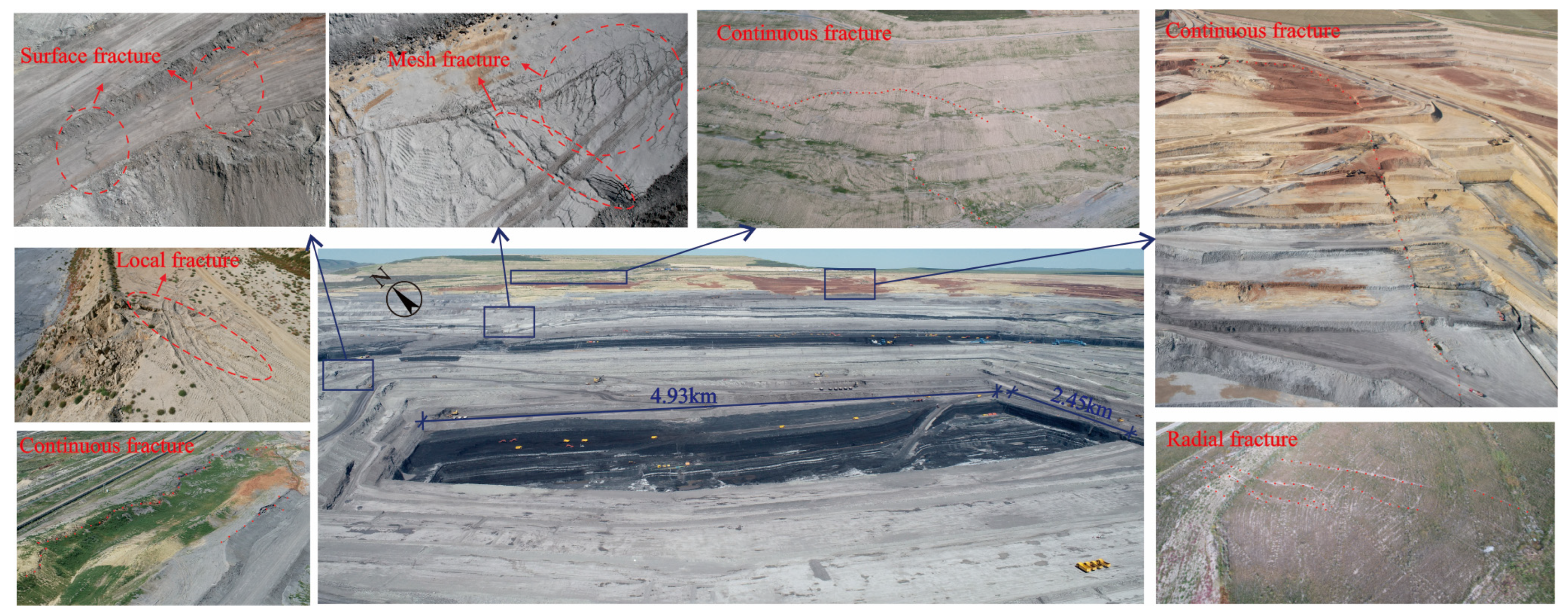
Figure 1. Current status of the study area.
Applsci 15 09960 g001
Figure 2. Typical engineering geological profile of the study area.
Applsci 15 09960 g002
Figure 3. Main weak interlayer exposed in the study area.
Applsci 15 09960 g003
Figure 4. Research methodology.
Applsci 15 09960 g004
Figure 6. Field sampling and laboratory tests.
Applsci 15 09960 g006
Figure 7. Triaxial compression creep test curve and suitability value curve.
Applsci 15 09960 g007
Figure 8. Numerical model.
Applsci 15 09960 g008
Figure 9. Slope displacement contour after 1 year of free deformation.
Applsci 15 09960 g009
Figure 10. Displacement curves of different monitoring points.
Applsci 15 09960 g010
Figure 11. Incremental contour of the plastic zone and plastic strain of the slope after 1 year of free deformation.
Applsci 15 09960 g011
Figure 12. Weak interlayer reinforcement scheme and the distribution and deformation of the plastic zone of the slope after 1 year of free deformation after reinforcement.
Applsci 15 09960 g012
Table 1. Loading scheme.
Confining StressAxial Stress (kPa)Confining StressAxial Stress (kPa)Confining StressAxial Stress (kPa)Duration
(h)
50 kPa10100 kPa20200 kPa30≥20 h
204050≥20 h
306080≥20 h
4080100≥20 h
45100130≥20 h
50120150≥20 h
Table 2. Parameters of the creep model for weak interlayers.
Parameters K / M P a G 1 / M P a G 2 / M P a η 1 / M P a · h η 2 / M P a · h c/kPa φ
Value (suitability function 1)7.3581.201.0250.39644.6521.349.02
Value (suitability function 2)16.470.9238.60734.8260.77
Table 3. Physical and mechanical parameters of rock and soil layers.
Parameters ρ / k g · m 3 E / M P a μc/kPaφ
Loose deposits18702900.273045
Cultivated soils1910510.2641.135.6
Clays1950670.2644.537.5
Gravel197010500.2522336.6
Mudstones204014800.23205.635.7
Table 4. Physical and mechanical parameters of the weak interlayer reinforcement.
Parameters ρ / k g · m 3 E / M P a μc/kPaφ
Reinforcement21403500.21500045
Disclaimer/Publisher’s Note: The statements, opinions and data contained in all publications are solely those of the individual author(s) and contributor(s) and not of MDPI and/or the editor(s). MDPI and/or the editor(s) disclaim responsibility for any injury to people or property resulting from any ideas, methods, instructions or products referred to in the content.