Article

Investigation of Grout Anisotropic Propagation at Fracture Intersections Under Flowing Water

1
School of Resources and Geosciences, China University of Mining and Technology, 1 University Road, Xuzhou 221116, China
2
Yiliang Chihong Mining Co., Ltd., Zhaotong 657602, China
3
National Coal Mine Water Hazard Prevention Engineering Technology Research Center, Suzhou 234000, China
*
Author to whom correspondence should be addressed.
Appl. Sci. 2025, 15(17), 9787; https://doi.org/10.3390/app15179787 (registering DOI)
Submission received: 29 July 2025 / Revised: 3 September 2025 / Accepted: 4 September 2025 / Published: 6 September 2025
(This article belongs to the Special Issue Hydrogeology and Regional Groundwater Flow)

Abstract

Grout propagation is a critical aspect of fracture grouting. This study investigated grout propagation at fracture intersections under flowing conditions using a simplified two-dimensional (2D) fracture network. Transparent soil technology was employed to simulate the porous filling material within the fractures. The results showed that the penetration velocity of grout decreased significantly after passing through an intersection, and the velocity in the main fracture was consistently higher than that in the branch fractures. In the unfilled fracture network, the diffusion ratio between branch and main fractures ranged from 0.35 to 0.88, whereas after filling, it ranged from 0.71 to 0.86. For each intersection, the ratio of grout length in the downstream branch to that in the main fracture (RDM) was positively correlated with branch width. This trend was especially evident in unfilled fractures, whereas in filled fractures, the increase in RDM was much less pronounced. Regarding the upstream ratio (RUM), it was consistently lower than RDM. RUM increased with branch width in unfilled fractures but decreased in filled fractures. Additionally, higher fluid velocity amplified these anisotropic propagation behaviors. Based on the simplified filled fracture model, it was concluded that porous filling materials reduce permeability differences between fractures with different aperture widths. Furthermore, increased flow rate intensified the anisotropic diffusion of grout. This study provides valuable insight into the mechanism of anisotropic grout propagation and offers guidance for engineering grouting applications.

1. Introduction

Grouting, one of the most widely used methods for blocking water and strengthening fractured rock masses [1,2], has been extensively applied in engineering projects [3]. However, due to the complexity of fracture networks, grout diffusion is often uneven and difficult to predict, frequently resulting in unsatisfactory outcomes [4].
To better understand grout diffusion behavior, many scholars have conducted experimental studies on grout propagation mechanisms in simplified fractures [5]. Wang et al. found that grout effectiveness is correlated with the coefficient of variation of aperture width under flowing water conditions when fracture roughness remains constant [6]. Hao et al. studied grout propagation in vertical fractures and revealed that gravity is a key factor influencing grout diffusion [7]. In reality, fractures intersect with each other, forming various types of fracture networks [8]. Recent work by Ding et al. [9] and Chen et al. [10] has demonstrated that grout behaves as a non-Newtonian fluid, and its propagation is strongly affected by the stress conditions and fracture connectivity, further complicating the grout diffusion process in more realistic fracture networks. Among them, the fracture intersections, as components of the fracture network, control the diffusion of the grout [11]. Tian established a cross-fracture model and demonstrated that groundwater tends to flow preferentially into wider fractures [12]. Building on this, Jiang et al. [13] carried out grouting experiments to examine grout propagation characteristics in fracture networks with variable aperture widths, while Zheng et al. [14] showed that anisotropic grout propagation in fracture networks is significantly influenced by fluid velocity. In previous studies, grout diffusion channels in fractures were often simplified as narrow grooves. In reality, however, fractures are frequently filled with sediments or other materials. In some cases, flowing water may also carry sediments, further exacerbating potential hazards [15]. It is generally recognized that factors such as aperture width, porosity, and the particle size of the filling material strongly influence the permeability of filled fractures [16]. Consequently, the diffusion behavior of grout is inevitably affected by the presence of filling media [17]. Nevertheless, due to the concealed nature of grouting processes, incorporating the effect of filling materials further complicates the visualization of grout diffusion, leaving research on grout behavior in filled fractures still very limited. Transparent soil, a novel experimental technique developed in recent years, provides an effective means of achieving visualization for such concealed problems [18,19]. The mechanical properties and permeability of transparent soil have been thoroughly investigated, and its validity and accuracy have been confirmed [20,21,22,23]. Moreover, transparent soil has been successfully applied to study fluid behavior within soil across a wide range of fields [24,25].
In this study, to investigate grout anisotropic propagation at fracture intersections, a simplified two-dimensional fracture network was established. A laboratory-scale experimental setup was designed to simulate grout propagation under dynamic flowing conditions, with transparent soil employed to model porous filling media. Grout propagation behavior at fracture intersections was captured, and the ratio of grout length between branch and main fractures was analyzed. The findings of this study contribute to a deeper understanding of grout propagation characteristics in fracture networks under complex conditions.

2. Materials and Methods

2.1. Background

The Maoping lead–zinc deposit is located in Yunnan Province, China, and is part of the well-known mining area. Figure 1a,b illustrate the location of the study area. To prevent and control water-related hazards, extensive grouting projects and experiments have been carried out in the mining area. However, the on-site diffusion behavior of the grout is difficult to predict, resulting in grouting effectiveness that is not always ideal This is particularly critical for chemical grouts, which are costly; any grout loss can lead to significant economic burdens. Figure 1c,d, respectively, show the complex fracture channels on site and a schematic diagram of the uneven diffusion of grout. To address this issue, this study simplifies the problem and conducts laboratory experiments to investigate grout diffusion along different preferential fractures.

2.2. Fracture Network Model

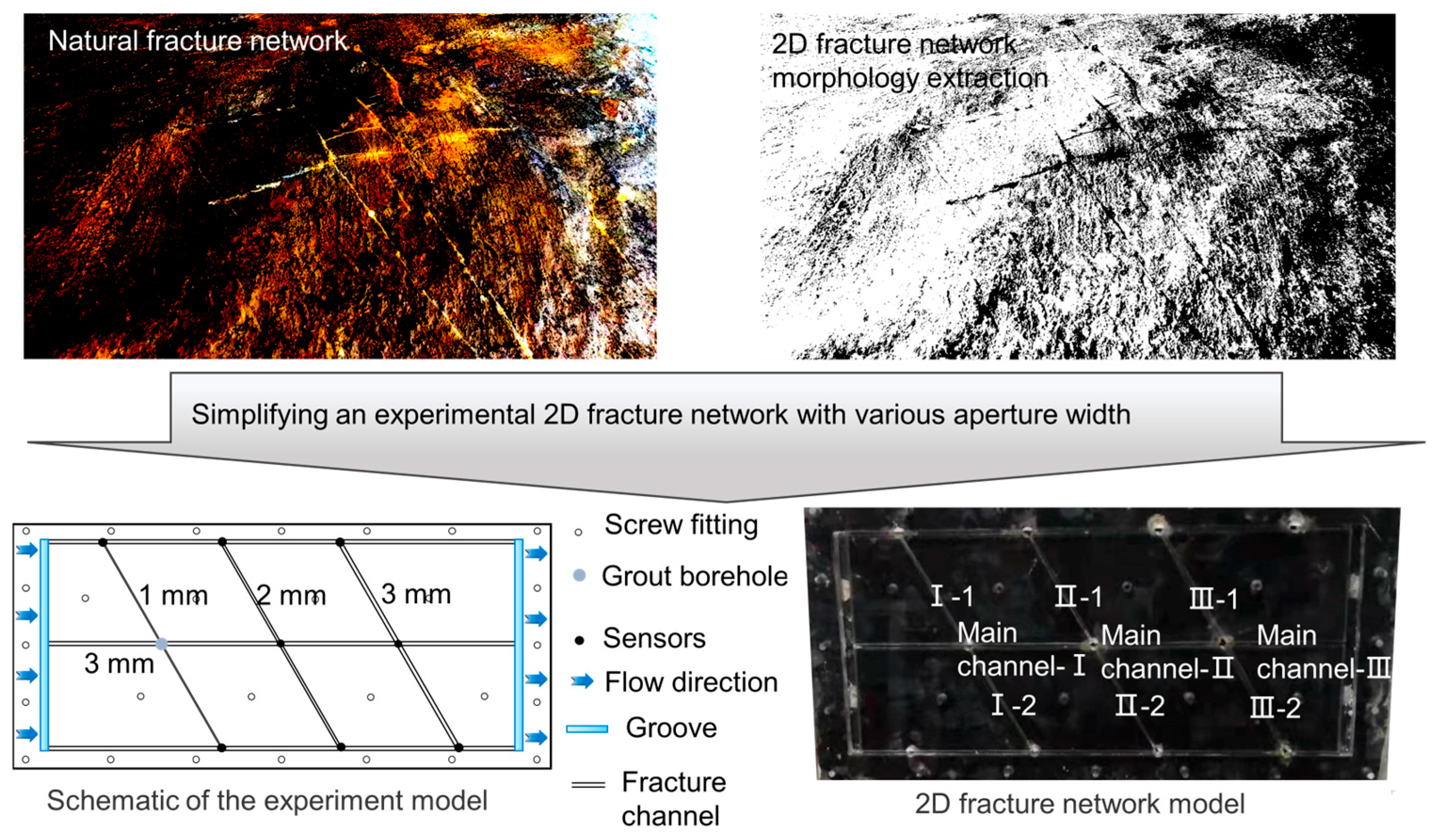
The grout diffuses unevenly at each fracture intersection, and this uneven diffusion is significantly influenced by the geometry of the fracture pathways. In previous studies, Jiang [13] first proposed simplifying the complex fracture intersection patterns in nature using a two-dimensional fracture network and further verified the mechanism of uneven grout diffusion [14]. Building on this previous work, in this study the fracture model was simplified by designing a main fracture with a width of 3 mm intersected by three branch fractures. These three branch fractures are parallel to each other, with apertures of 1 mm, 2 mm, and 3 mm, respectively, and intersect the main fracture at an angle of 60°. The simplified fracture network was established, as shown in Figure 2. The intersections with branch widths of 1 mm, 2 mm, and 3 mm are referred to as intersection I, intersection II, and intersection III, respectively. Two grooves were set at the inlet and outlet of the main pathway to ensure flow stability. The fracture network model was fabricated using polymethyl methacrylate (PMMA), which offers good transparency. It consisted of two plates fastened together with screws. The aperture widths were selected according to the classification by the International Society for Rock Mechanics [26].

2.3. Filling Material

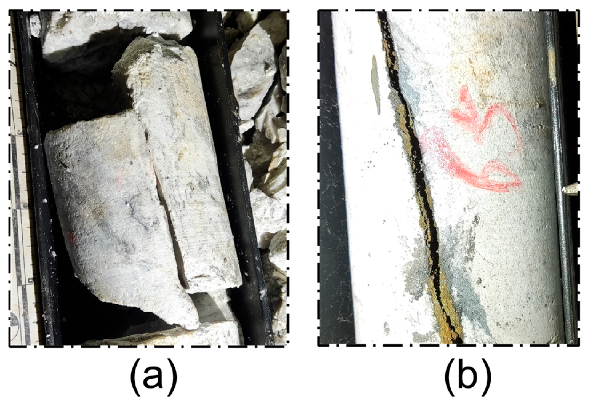
In addition, field investigations in the mining area revealed that many fractures are filled with silty materials (Figure 3b). Shao et al. [16] proposed that the filling medium within the fractures can significantly affect their permeability. To account for the influence of the filling material, this study introduces transparent soil into the grouting channels to enable visual observation.
It has been verified that transparent soil is a good option in visualizing the grout propagation process [27]. Transparent soil is made from transparent solid skeleton and pore fluid with the same refractive index. Fused silica and mixed mineral oil were used in this study. The properties of the mineral oil and fused silica are shown in Table 1 and Table 2, respectively. In the study of the filled fracture, fused silica filled the fracture pathways in advance, acting as the filling material. The mixed mineral oil, which has the same refractive index, acted as the pore fluid and cycled to simulate the flowing water.

2.4. Grout Material

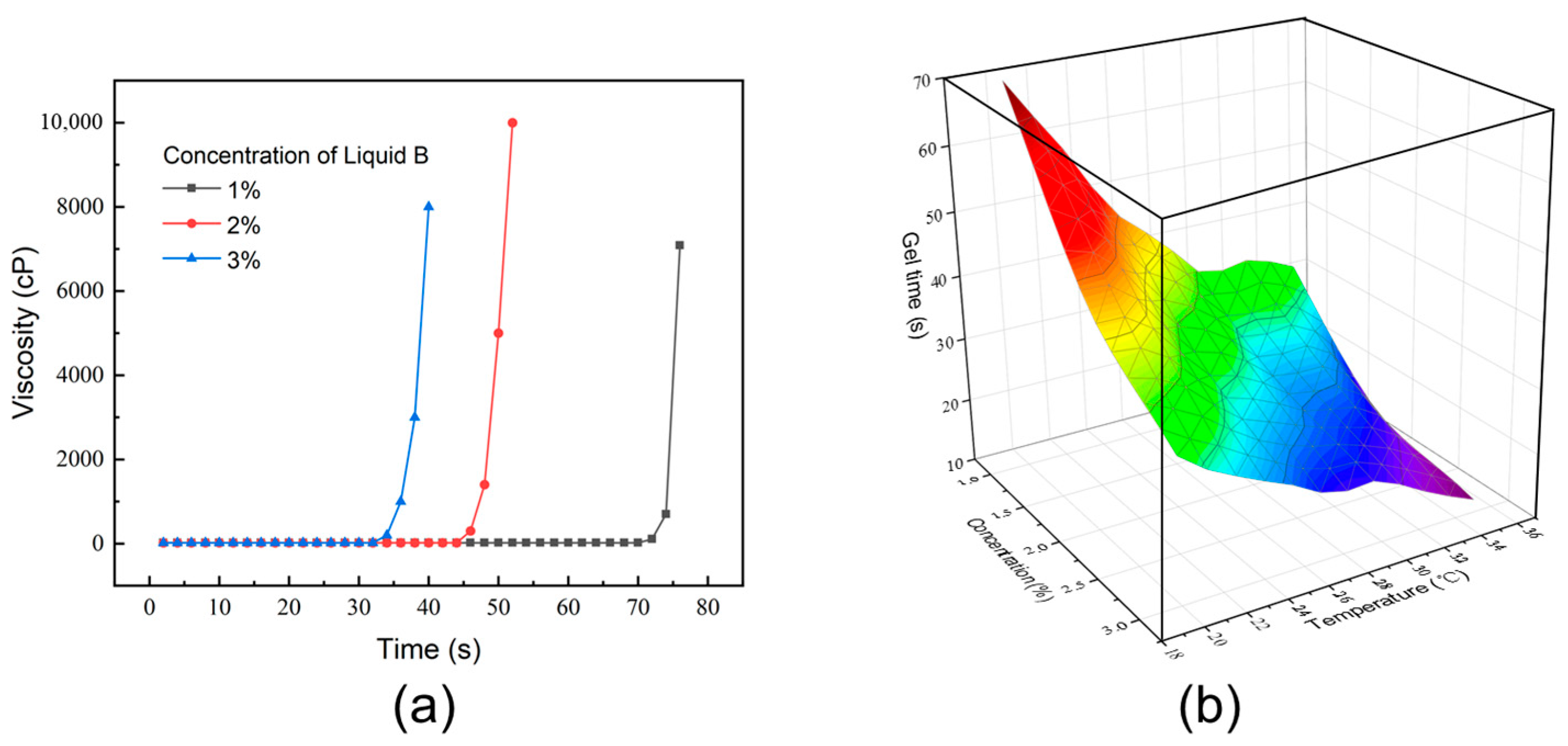
Chemical grout is different from traditional cement grout as it is a kind of fluid with good permeability before gel. The grout used in this experiment is a kind of acrylic chemical grouting material, which has been extremely popular in engineering. Especially, it is a good choice for grouting in the narrow fracture because of its low viscosity, good permeability, and stable rheological properties before gel. This grout material consists of the main resin composition and the curing agent. The curing agent is a kind of soluble powder, and solutions with different concentrations can vary the gel time. Figure 4a shows the viscosity changes with different concentrations of curing agent at 20 °C.
The law for the variation in viscosity with time of this material can be expressed as
μ t = μ 0 + A e k t
where μ t and μ 0 are the viscosity at time t and the initial time, respectively.
In addition, this material is sensitive to temperature and the gel time will change when the temperature changes. The relationship among gel time, concentration of curing agent, and temperature is shown in Figure 4b. The gel time decreases with the increase in temperature and the concentration of curing agent. During the experiment, the temperature is controlled at 20 °C and the concentration of curing agent is 2%.

2.5. Experimental Setup

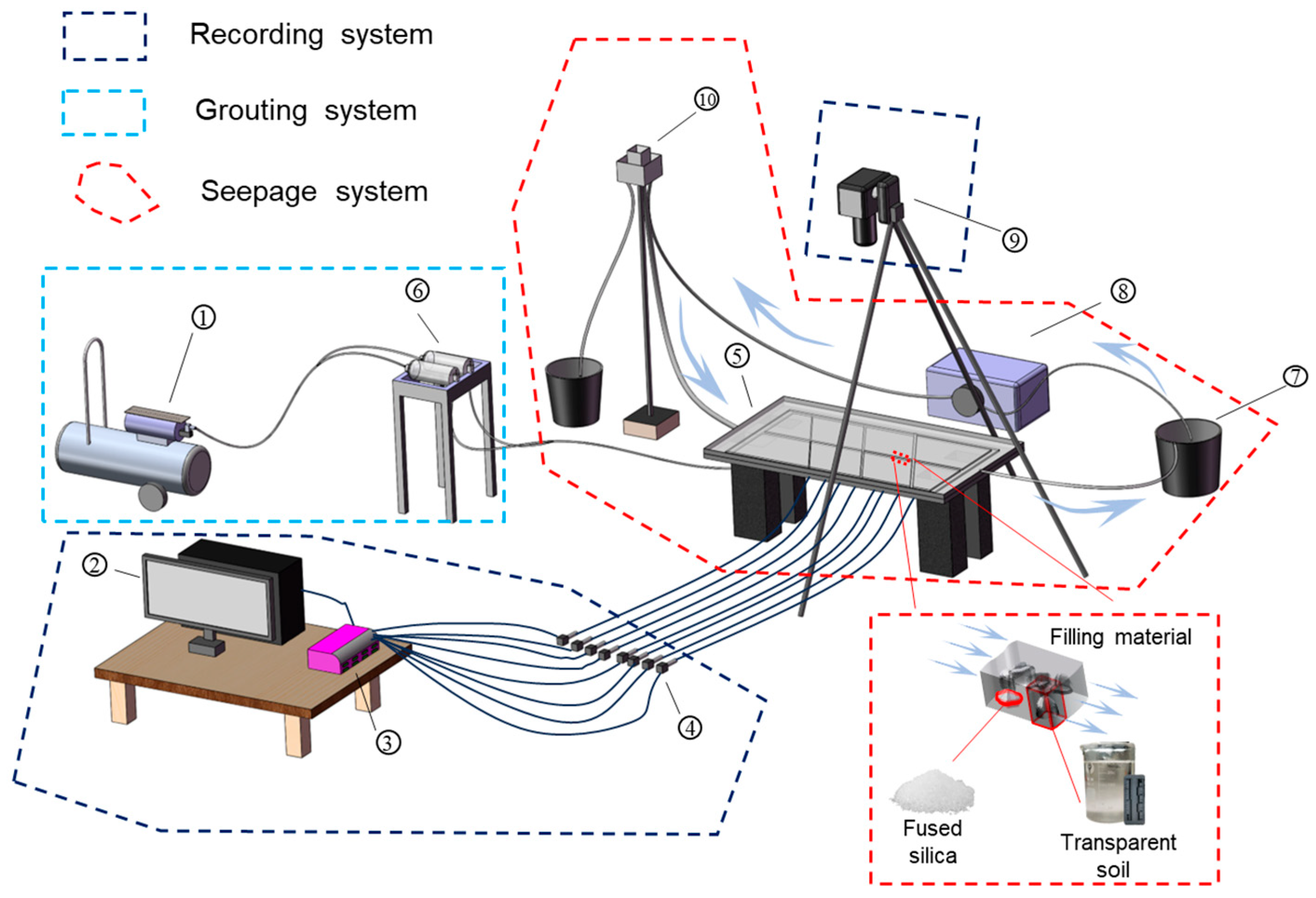
The experimental setup is shown in Figure 5 and can be divided into three parts: the seepage system, the grouting system, and the recording system. First, before grouting, the prepared mineral oil mixture was placed in the fluid storage bottle. Then, the peristaltic pump delivered the fluid to the water level control device. The water level control device provides a stable fluid flow to the fracture model to simulate seepage through the fracture network. Its height can be adjusted to control the initial water pressure. The blue arrows indicate the fluid circulation.
In the study of grouting in filled fractures, the fracture pathway was pre-filled with fused silica to simulate a filled fracture. Two chambers were used to store the grout components. Then, an air compressor injected the grout into the fracture model to simulate the grouting process. Pressure sensors monitored the seepage pressure during the experiment, and the data were recorded by the data logger. A camera was used to record the grout propagation process. The data from the data logger and the images of grout propagation were transferred to a computer for data recording. In this study, the porosity of the fissure-filling medium was set to 0.3, the grouting pressure was 0.1 MPa, and the water level device was positioned at a height of 1 m.

3. Results

3.1. Subsection

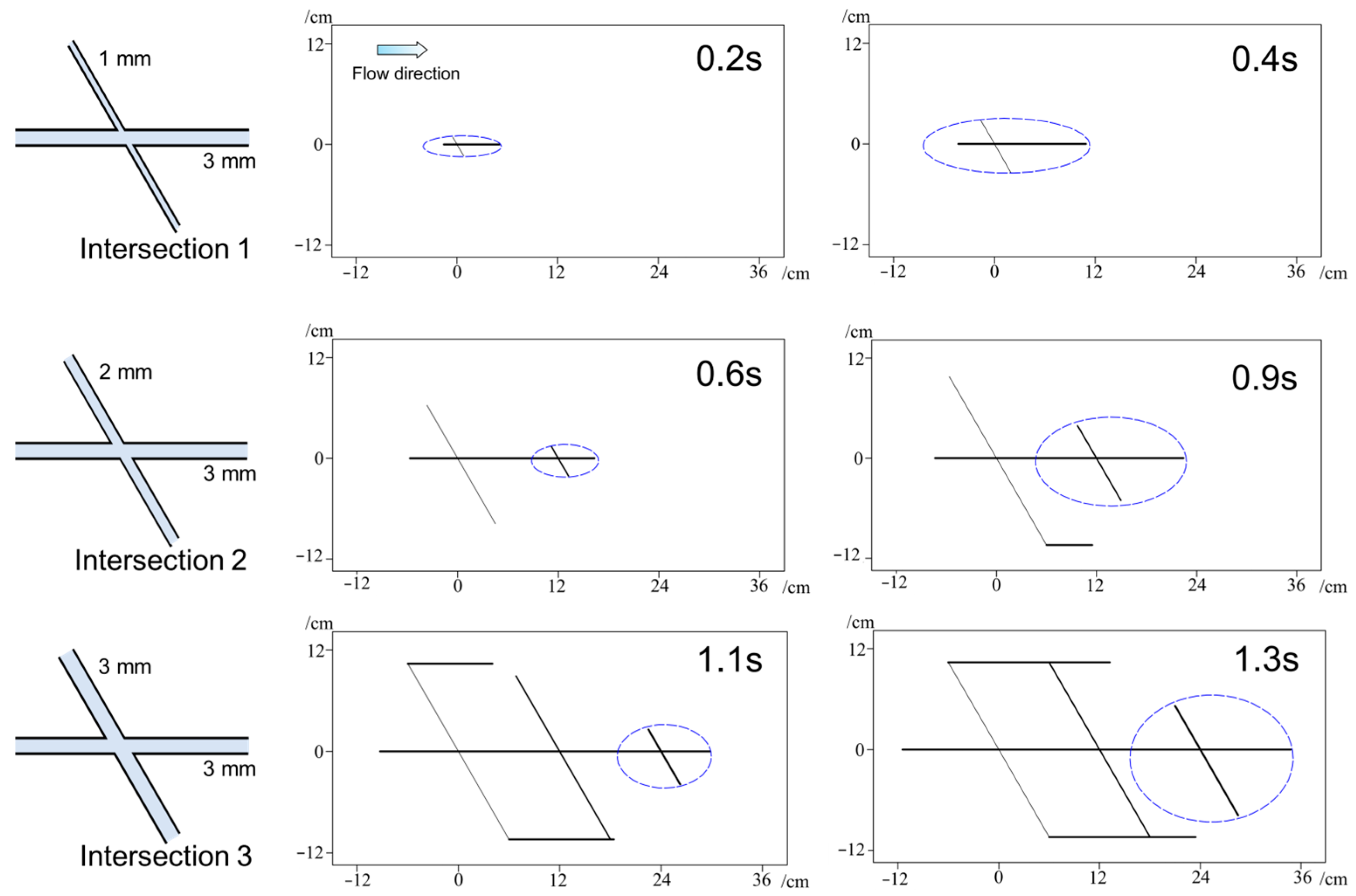
The diffusion processes of grout at different intersections were extracted. Figure 6 shows the diffusion characteristics of grout at three fracture intersections. The black color represents the grout diffusion path, while the blue ellipses indicate the diffusion ratio between the main fracture and the branch fracture. The results indicate that the grout diffused unevenly between the branch and the main fractures. Moreover, the difference in diffusion between the branch and the main fractures gradually decreased from intersections I to III.
Figure 7 shows the variation in diffusion distance over time during grout propagation in different fracture pathways. Based on linear fitting curves, the average diffusion velocities of grout in the main pathways at intersections I, II, and III were 48.8, 22.3, and 16.0 cm/s, respectively. The average velocities in branch fractures I-1, II-1, and III-1 were 17.2, 11.6, and 11.4 cm/s, while those in branch fractures I-2, II-2, and III-2 were 21.6, 14.2, and 14.1 cm/s, respectively. At intersection I, the diffusion velocity in branch fracture I-1 was only 0.35 times that of the main fracture, while in branch fracture I-2 it was 0.44 times that of the main fracture. This indicates a strong preferential flow through the main fracture.
At intersection II, the diffusion velocity in branch II-1 was 0.52 times that of the main fracture, and in branch II-2 it was 0.64 times. This suggests that the dominance of the main pathway was reduced compared with intersection I, though it still maintained a notable advantage over the branches.
By intersection III, the disparity was further diminished. The diffusion velocity in branch III-1 and branch III-2 was 0.71 and 0.88 times that of the main fracture, respectively. This trend demonstrates that the anisotropy of grout propagation at fracture intersections weakens progressively from intersection I to intersection III, reflecting a gradual balancing of flow between the main and branch fractures.

3.2. Grout Propagation in the Filled Fractures

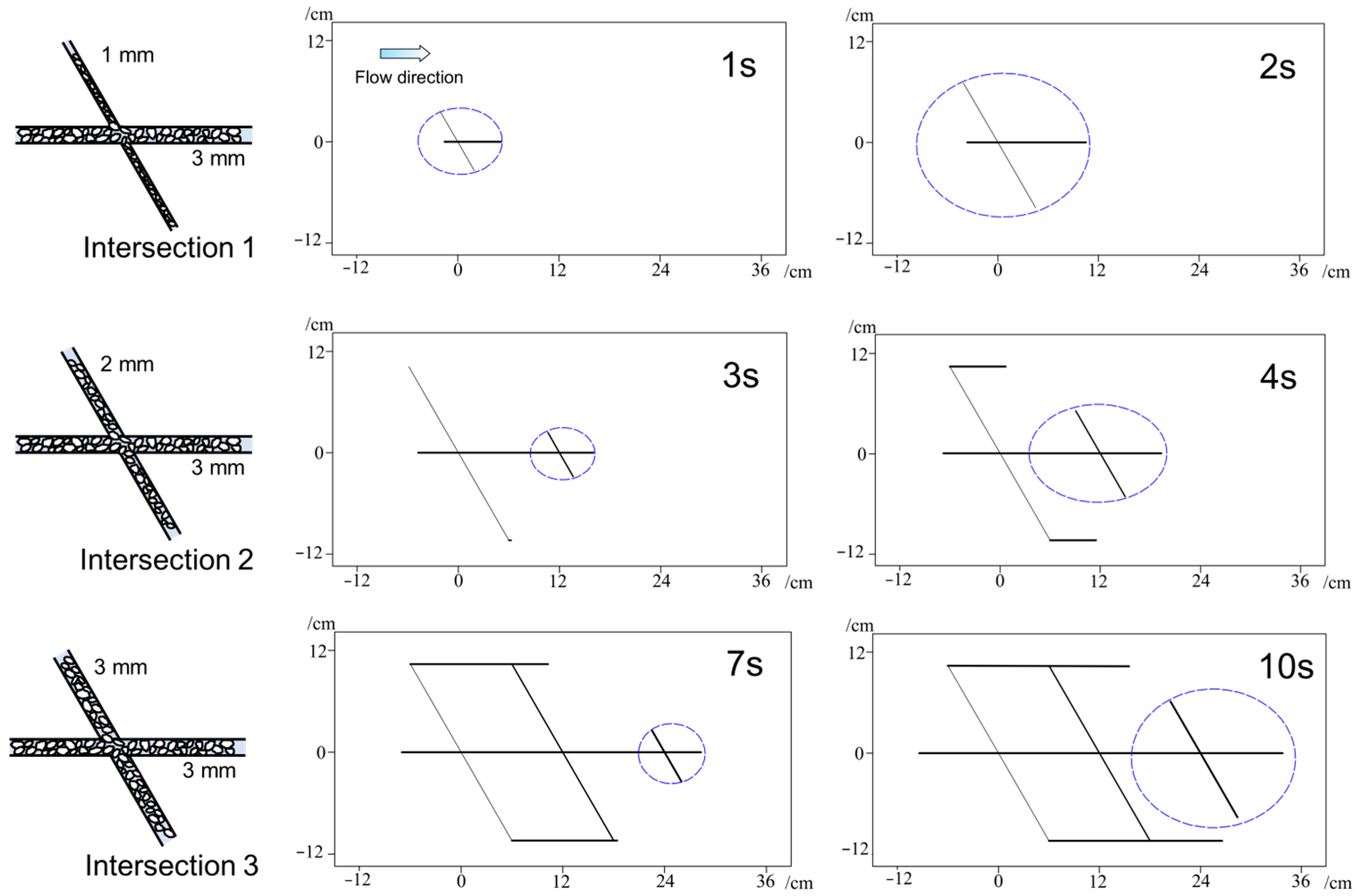
Figure 8 shows the grout diffusion path characteristic and Figure 9 shows the diffusion distance of the grout when sand filling material is present in the fracture pathway. When grout diffuses through different sand-filled fractures, the difference in diffusion behavior between the main and branch fractures is minimal. Based on the linear fitting curves in Figure 9, the average diffusion velocities of grout in the main pathways I, II, and III were 5.37, 3.36, and 1.76 cm/s, respectively. In branch fractures I-1, II-1, and III-1, the average velocities were 4.12, 2.62, and 1.24 cm/s, while in branch fractures I-2, II-2, and III-2, they were 4.62, 2.75, and 1.43 cm/s, respectively. In the filled fracture, the diffusion velocity of grout in branch fracture I-1 was 0.77 times that of the main fracture, in II-1 it was 0.78 times, and in III-1 it was 0.71 times. Furthermore, the diffusion velocity in branch fractures I-2, II-2, and III-2 was 0.86, 0.82, and 0.81 times that of the main fracture, respectively. The results indicate that there was no significant difference in diffusion velocity between the main and branch fractures at intersections I and II. However, compared with III-1, the notably higher velocity of grout diffusion in branch III-2 suggests a possible anomaly or a localized variation in the fracture structure or the filling material.

4. Discussion

4.1. Grout Propagation in the Unfilled Fractures

It is widely recognized that aperture width is a key factor influencing fracture permeability. In nature, fractures are interwoven to form complex networks, within which the laws governing fluid migration are highly intricate. Some researchers have focused on the basic units of fracture networks—namely, the intersections. Starting from the influence of fracture width on flow distribution, Tian [12] found that fluid tends to flow preferentially into the wider fracture at intersections and proposed the concept of the deflection effect. Jiang et al. [13] constructed a fracture network with varying widths to investigate grout diffusion behavior. Their experiments showed that grout also tended to propagate in the direction of wider fractures under flowing conditions. More recently, Zheng et al. [14] derived a quantitative relationship between grout diffusion distance and fracture aperture, revealing a positive correlation between crack opening and diffusion distance. In this study, a similar phenomenon was observed when grout propagated through unfilled fracture intersections. The experimental results also show that the relative differences between the main and branch fractures are much smaller and more consistent, suggesting that fracture filling reduces anisotropy and balances grout propagation across pathways.

4.2. Grout Propagation in the Filled Fractures

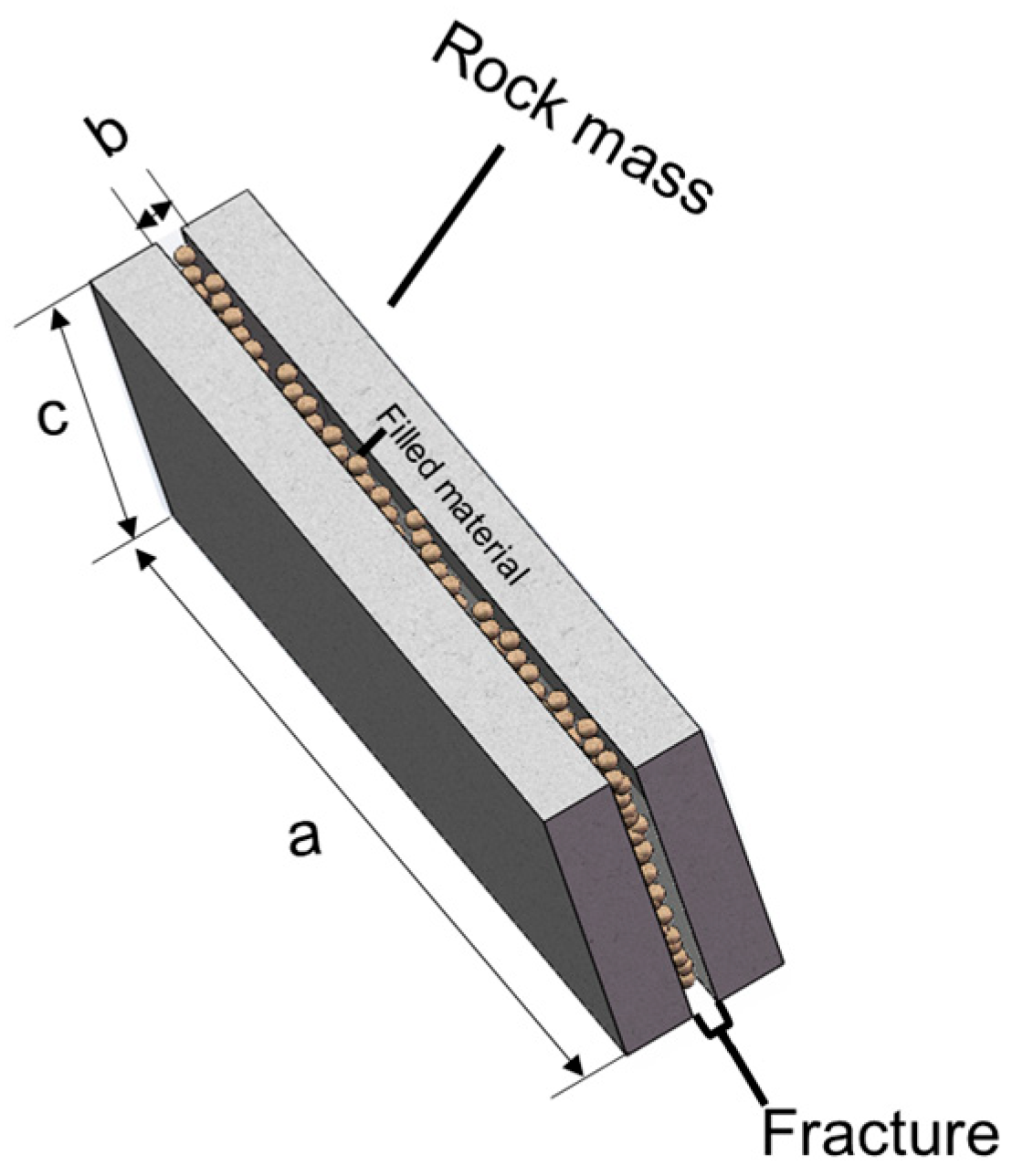
When a fracture is filled with porous media, its permeability changes significantly. The permeability of such a filled fracture is influenced by the interaction between the porous filling material and the fracture aperture boundaries. Su et al. [28] assumed that the geometry of the filled fracture could be represented as shown in Figure 8, where the porous filling material was simplified as spherical particles with an average diameter d. Since this study focuses on fluid behavior in two-dimensional fracture intersections, the fracture is assumed to extend infinitely in the transverse direction. Under these assumptions, a seepage velocity equation (Equation (2)) based on the Kozeny–Carman equation was proposed by Miyazaki [29].
v f = g e 3 b 2 20.4 ν α 2 1 + 3 1 e b d 2 J
where v f is the average velocity in the filled fracture, α is the particle shape factor, ν is the kinematic viscosity, J is the hydraulic gradient, and e is the porosity.
Based on the modified porous media model (Figure 10), grout propagation in filled fracture networks is more likely influenced by the properties of the filling material and the aperture width. Sui et al. [27] later validated this equation for grout propagation using transparent soil techniques.
In this study, the hydraulic conductivity K is considered as
K = g e 3 b 2 20.4 ν α 2 1 + 3 1 e b d 2
The permeability of the filled fracture (k) is given by
k = K μ ρ g = e 3 b 2 20.4 α 2 1 + 3 1 e b d 2
For filled fractures with widths of 1, 2, and 3 mm, the corresponding parameters are listed in Table 3.
It was found that when the fracture contains filling material, the permeability does not change significantly with increasing branch width. The experimental results also show that the relative differences between the main and branch fractures are smaller and more consistent, indicating that fracture filling reduces anisotropy and promotes a more balanced grout propagation across pathways.

4.3. Numerical Simulation

Since grout propagation is a complex process, numerical simulation can be an effective approach for analysis [30]. The fluid behavior can be accurately modeled using the incompressible form of the Navier–Stokes equations (Equation (5)), while the continuity equation (Equation (7)) is used to represent the conservation of mass.
ρ u t + ρ u · u = · p I + K + F
K = μ u + u T
ρ t + ρ u = 0
where ρ is the density, u is the velocity vector, p is pressure, K is the viscous stress tensor, F is the volume force vector, and μ is the fluid’s dynamic viscosity.
However, based on the discussion above, grout propagation in filled fractures is better represented as flow through a porous medium. In this case, Darcy’s law provides a more appropriate model for fluid behavior:
u = k μ p
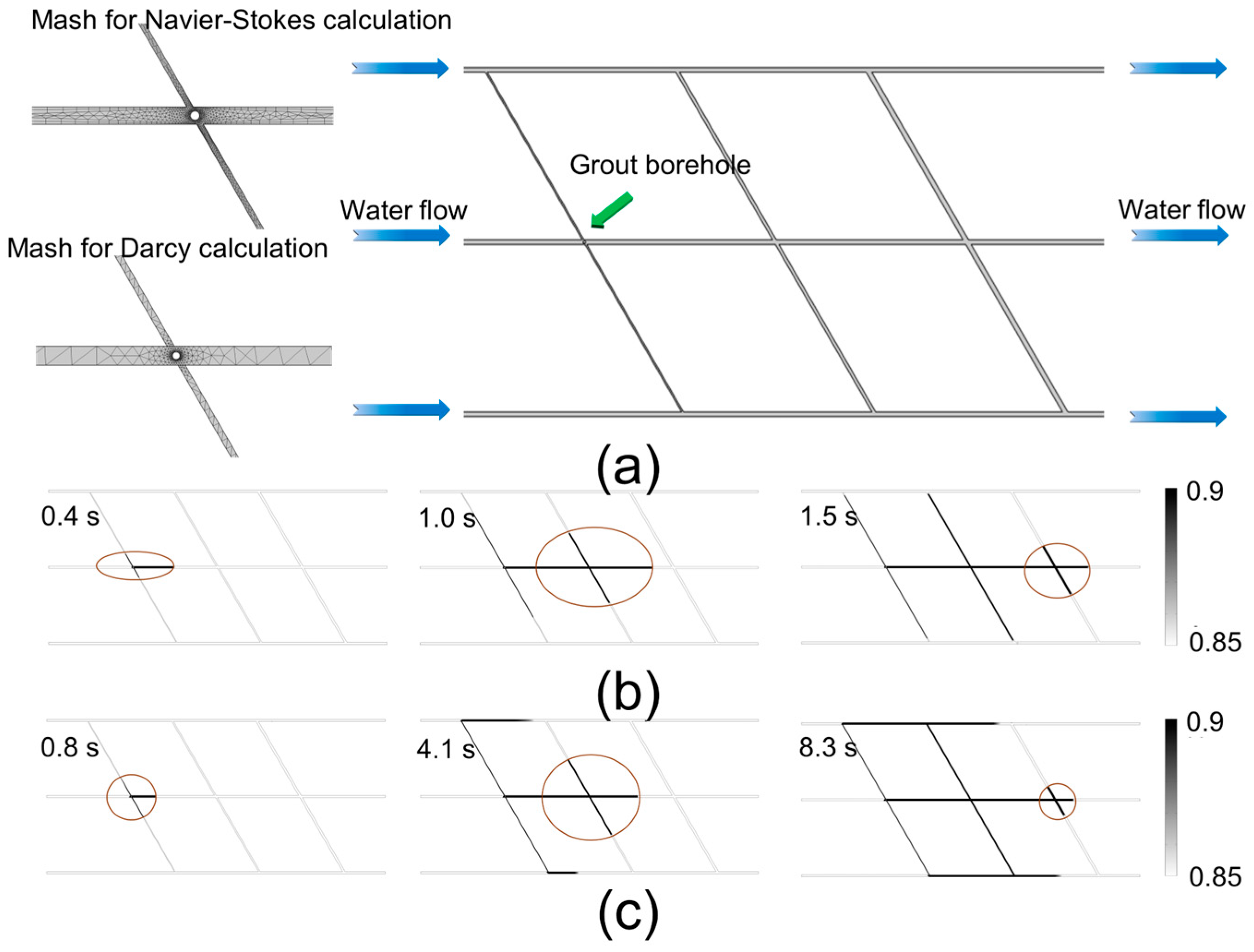
To verify the experimental results, numerical simulations of grout propagation under flowing conditions were conducted using COMSOL Multiphysics 5.6. For unfilled fractures, grout propagation under flow was simulated using the phase-field method [31], while for filled fractures, it was treated as a two-phase flow in porous media [32].
From the experimental setup, when the initial water level was maintained at 1 m, the measured outflow and flow velocity in the unfilled fracture were 4.5 mL/s and 3.2 cm/s, respectively. Under the same conditions, for the filled fracture, the outflow was approximately 1.1 mL/s and the velocity in the main pathway was about 0.95 cm/s. The grout had a density of 1200 kg/m3 and a viscosity of 5.5 cP. The numerical and experimental models were of equal scale.
Figure 11 shows the numerical model and simulation results obtained using both the Navier–Stokes equations and Darcy’s law. The grout diffusion patterns in the simulations closely resembled the experimental results shown in Figure 6 and Figure 8.

4.4. Ratio of Grout Penetration Length in Branch and Main Pathway

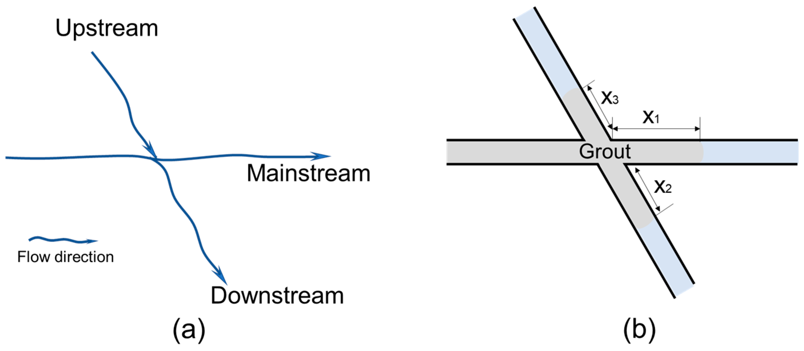
The pore pressures were monitored prior to the grout injection experiments, and the fluid flow direction was determined as shown in Figure 12a. Accordingly, each fracture intersection contains an upstream branch and a downstream branch, resulting in slight differences in grout propagation lengths.
The grout length in both the branches and the main fracture was recorded as the grout reached each intersection. To further analyze the grout diffusion behavior, two diffusion ratios were defined. In the upstream branch, the ratio of grout length in the upstream branch to that in the main pathway is defined as RUM. In the downstream branch, the ratio is defined as RDM.
R U M = x 3 x 1
R D M = x 2 x 1
where x1 is the slurry diffusion distance in the main fracture, x2 is the downstream slurry diffusion distance, and x3 is the upstream slurry diffusion distance.
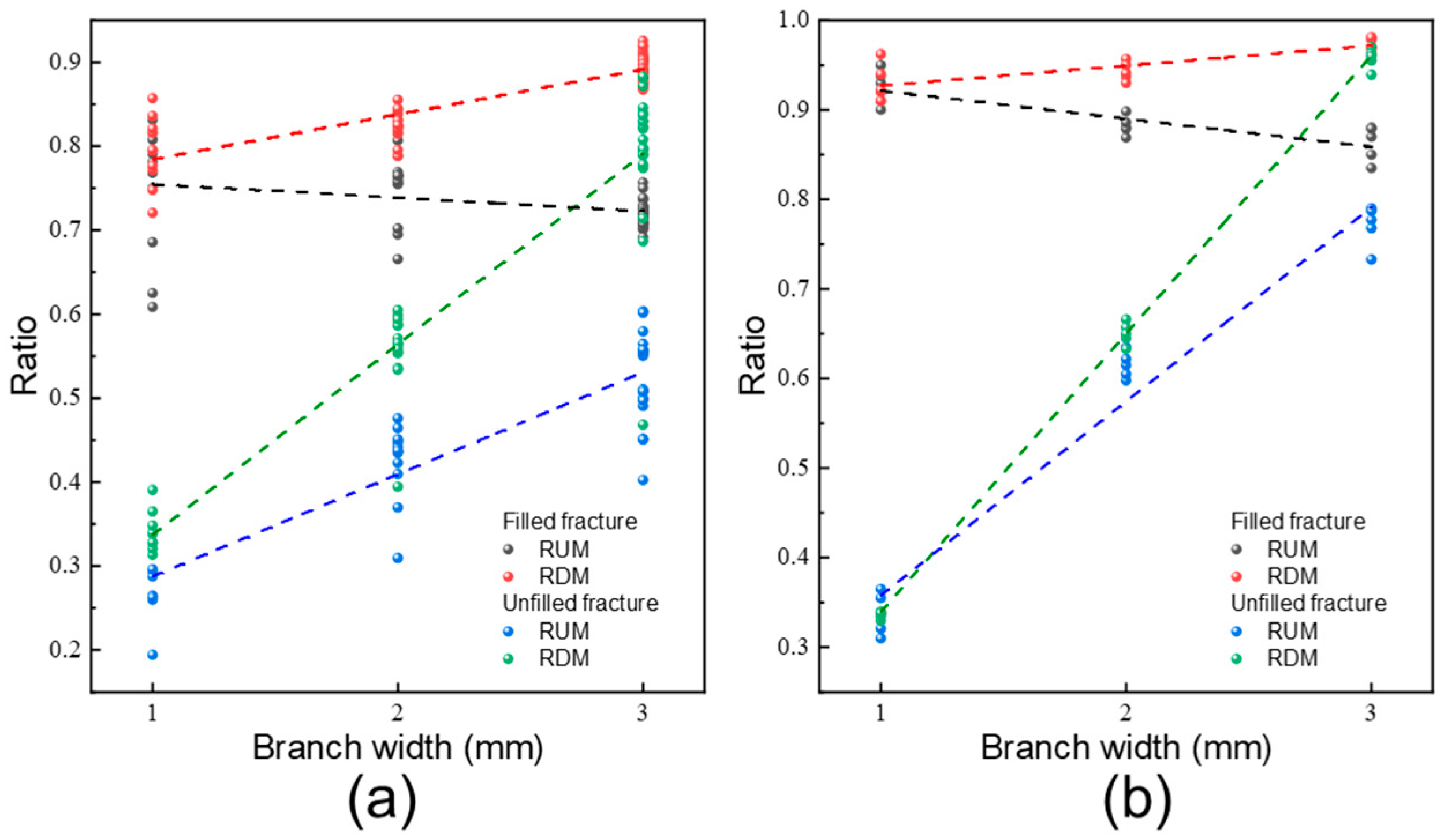
Figure 13 presents the diffusion ratios at the three intersections, where Figure 13a shows the experimental results. For unfilled fracture intersections, both diffusion ratios increased with increasing branch width. Considering the influence of fluid flow, the downstream diffusion ratio increased more rapidly than the upstream ratio as the branch opening increased. In contrast, for filled fracture intersections, grout lengths in the branches were nearly equal to those in the main pathway and showed little sensitivity to fracture width. Interestingly, the upstream diffusion ratio (RUM) even decreased with increasing aperture, indicating a reduced deflection effect in porous-filled fractures.

4.5. Effect of Fluid Velocity

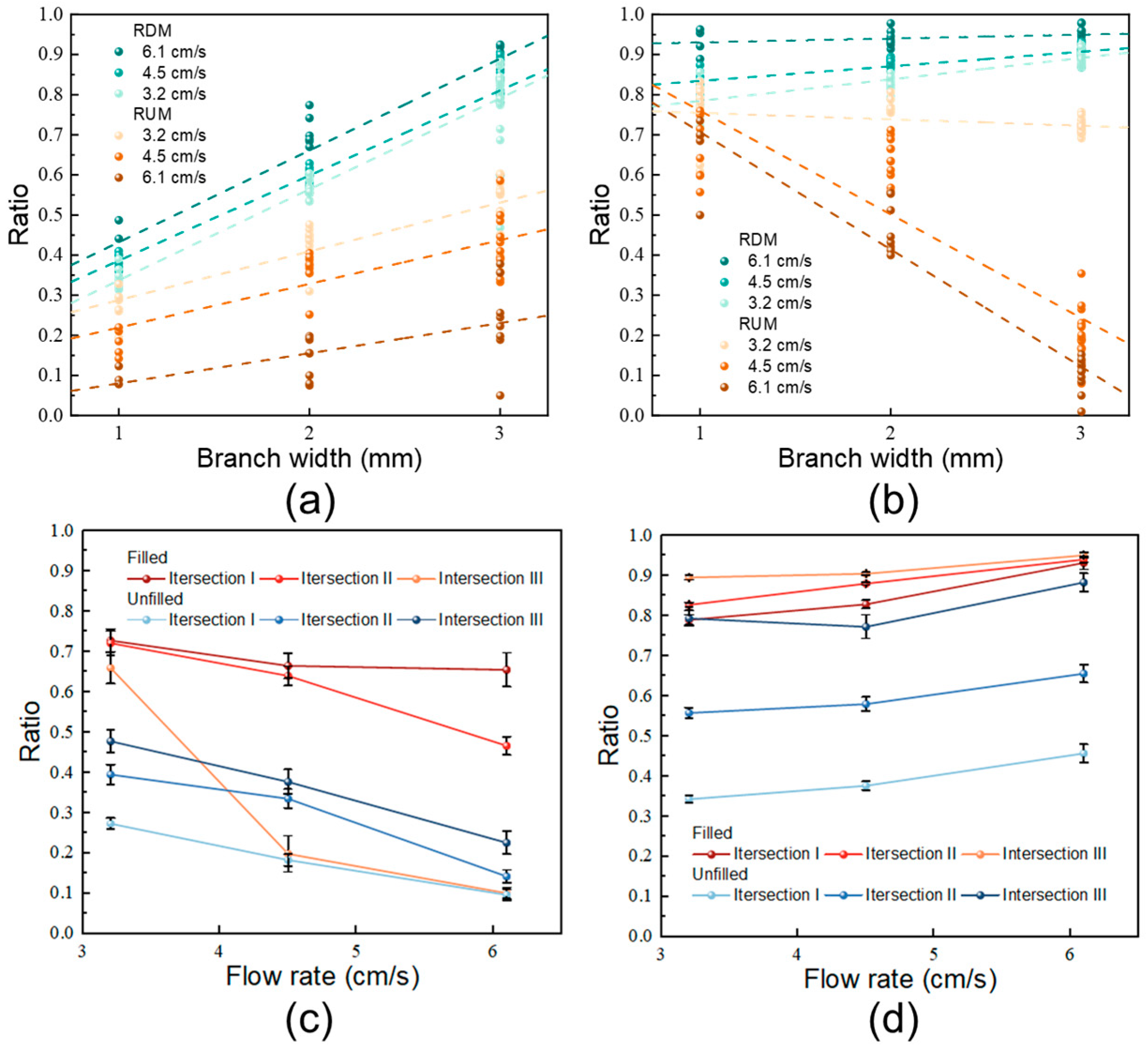
Fluid velocity is a key factor controlling the anisotropic propagation of grout [14]. The influence of fluid velocity on grout propagation is further analyzed in Figure 14. Under varying fluid velocities, both RDM and RUM exhibited similar trends with increasing branch width (Figure 14a,b). However, the gap between RDM and RUM widened as fluid velocity increased. This effect was even more pronounced in the filled fracture network, where RUM decreased significantly with increasing fluid velocity. In contrast, RDM continued to increase as fluid velocity increased, while RUM showed a consistent downward trend (Figure 14c,d). The impact of fluid velocity was particularly evident in the upstream region of filled intersection III. Based on this, for unfilled water-conducting channels, grouting should be carried out at locations with uniformly developed fractures to ensure even diffusion of the grout. In contrast, for filled fractures, grouting should primarily be considered at locations with low dynamic water flow velocity in order to achieve uniform diffusion.

4.6. Limitation

To better visualize grout diffusion in intersecting fractures, this study established a simplified two-dimensional fracture network model. However, in reality, fracture networks are highly complex, with varying dip angles, scales, and orientations, and the diffusion behavior of grout also differs across individual fractures. These aspects will be further investigated in future research.

5. Conclusions

In this study, a simplified two-dimensional fracture network model was established, and transparent soil was used to simulate the filling material. A laboratory-scale experimental setup for grouting under dynamic water conditions was then developed to investigate grout propagation at fracture intersections with varying aperture widths.
(1)
In the unfilled fracture network, the diffusion ratio between branch and main fractures increased progressively from 0.35–0.44 at intersection I to 0.71–0.88 at intersection III, indicating a gradual weakening of anisotropy and a more balanced flow distribution. After filling, the ratios became more stable, ranging from 0.71 to 0.86 across all intersections, which suggests that fracture filling further reduces anisotropy and promotes more uniform grout propagation between main and branch fractures.
(2)
RDM was positively correlated with branch width. This trend was especially evident in unfilled fractures, while in filled fractures the increase in RDM was much less pronounced.
(3)
RUM was consistently lower than RDM. In unfilled fractures, RUM increased with branch width, whereas in filled fractures it decreased. Fluid velocity further amplified these anisotropic propagation behaviors.
(4)
The presence of porous filling material reduced the permeability differences between fractures with different apertures.

Author Contributions

Conceptualization, B.S., X.M. and W.S.; methodology, D.L.; software, X.L. (Xuebin Liu); validation, Q.H. and X.L. (Xiaoxiong Li); formal analysis, X.M.; investigation, D.L.; writing—original draft preparation, B.S.; writing—review and editing, W.S. All authors have read and agreed to the published version of the manuscript.

Funding

This study was funded by the National Natural Science Foundation of China under Grant No. 42172293.

Data Availability Statement

Dataset available on request from the authors.

Conflicts of Interest

Authors B.S., D.L., X.L. (Xuebin Liu), Q.H. and X.L. (Xiaoxiong Li) were employed by the company Yiliang Chihong Mining Co., Ltd. The remaining authors declare that the research was conducted in the absence of any commercial or financial relationships that could be construed as a potential conflict of interest.

References

  1. Zhou, D.; Zhao, Z.; Li, B.; Chen, Y.; Ding, W. Permeability evolution of grout infilled fractures subjected to triaxial compression with low confining pressure. Tunn. Undergr. Space Technol. 2020, 104, 103539. [Google Scholar] [CrossRef]
  2. Boschi, K.; Giulio di Prisco, C.; Grassi, D.; Modoni, G.; Salvatore, E. Nanosilica grout permeation in sand: Experimental investigation and modeling. J. Geotech. Geoenviron. Eng. 2024, 150, 04023129. [Google Scholar] [CrossRef]
  3. Meng, X.; Sui, W.; Zhou, C.; Xie, B. Unraveling the Dynamic Failure-Stress Feedback Mechanism in Mining Overburden Through the PIV-DEM Synergistic Analysis. Int. J. Numer. Anal. Methods 2025. [Google Scholar] [CrossRef]
  4. Cao, N.; Huo, Z.; Liang, Y.; Zhang, L.; Yao, H. Research on slurry seepage law and in-situ test based on the 3-D of goaf porosity in CFD modeling. Fuel 2024, 361, 130701. [Google Scholar] [CrossRef]
  5. Jin, Y.; Han, L.; Xu, C.; Meng, Q.; Zong, Y. Cement grout nonlinear flow behavior through the rough-walled fractures: An experimental study. Geofluids 2020, 2020, 9514691. [Google Scholar] [CrossRef]
  6. Wang, Y.; Yang, P.; Li, Z.; Wu, S.; Zhao, Z. Experimental-numerical investigation on grout diffusion and washout in rough rock fractures under flowing water. Comput. Geotech. 2020, 126, 103717. [Google Scholar] [CrossRef]
  7. Hao, M.; Song, T.; Li, X.; Zou, L.; Zhong, Y.; Zhang, B.; Wang, L. Propagation analysis of polymer grout in vertical fractures: An experimental and numerical study. KSCE J. Civ. Eng. 2024, 28, 1217–1226. [Google Scholar] [CrossRef]
  8. Yan, C.; Tong, Y.; Luo, Z.; Ke, W.; Wang, G. A two-dimensional grouting model considering hydromechanical coupling and fracturing for fractured rock mass. Eng. Anal. Bound. Elem. 2021, 133, 385–397. [Google Scholar] [CrossRef]
  9. Ding, W.; Lei, B.; Duan, C.; Zhang, Q. Numerical simulation of grout diffusion in rough rock fractures considering multiple influencing factors. Rock Mech. Rock Eng. 2024, 58, 355–377. [Google Scholar] [CrossRef]
  10. Chen, Y.; Sun, D.; Shao, Y.; Ma, G. A model of cement grout flow in a fracture network system. Comput. Geotech. 2024, 175, 106698. [Google Scholar] [CrossRef]
  11. Xiong, F.; Wei, W.; Xu, C.; Jiang, Q. Experimental and numerical investigation on nonlinear flow behavior through three-dimensional fracture intersections and fracture networks. Comput. Geotech. 2020, 121, 103446. [Google Scholar] [CrossRef]
  12. Tian, K. The hydraulic properties of crossing-flow in an intersected fracture. Acta Geol. Sin. 1986, 60, 202–214. [Google Scholar]
  13. Jiang, X.; Zheng, G.; Sui, W.; Chen, J.; Zhang, J. Anisotropic propagation of chemical grouting in fracture network with flowing water. ACS Omega 2021, 6, 4672–4679. [Google Scholar] [CrossRef]
  14. Zheng, G.; Sui, W.; Zhang, G.; Chen, J.; Zhang, D. Propagation and sealing efficiency of chemical grouting in a two-dimensional fracture network with flowing water. Int. J. Rock Mech. Min. 2023, 33, 903–917. [Google Scholar] [CrossRef]
  15. Feng, L.; Huang, F.; Wang, G.; Huang, T.; Qian, Z. Experimental investigation on pneumatic pre-fracturing grouting in low-permeability soil. Tunn. Undergr. Space Technol. 2023, 131, 104798. [Google Scholar] [CrossRef]
  16. Shao, J.; Zhang, Q.; Wu, X.; Lei, Y.; Wu, X.; Wang, Z. Investigation on the water flow evolution in a filled fracture under seepage-induced erosion. Water 2020, 12, 3188. [Google Scholar] [CrossRef]
  17. Zhuo, Z.; Li, R. Theoretical and experimental study on one-dimensional fracture grouting in soil medium. Sadhana-Acad. P. Eng. S. 2020, 45, 117. [Google Scholar] [CrossRef]
  18. Wang, Z.; Li, C.; Ding, X. Application of transparent soil model tests to study the soil-rock interfacial sliding mechanism. J. Mt. Sci.-Engl. 2019, 16, 935–943. [Google Scholar] [CrossRef]
  19. Iskander, M.; Bathurst, R.J.; Omidvar, M. Past, present, and future of transparent soils. Geotech. Test. J. 2015, 38, 557–573. [Google Scholar] [CrossRef]
  20. Huang, B.; Guo, C.; Tang, Y.; Guo, J.; Cao, L. Experimental study on the permeability characteristic of fused quartz sand and mixed oil as a transparent soil. Water 2019, 11, 2514. [Google Scholar] [CrossRef]
  21. Iskander, M. Modeling with Transparent Soils: Visualizing Soil Structure Interaction and Multi-Phase Flow, Non-Intrusively; Springer: Berlin/Heidelberg, Germany, 2010. [Google Scholar]
  22. Yuan, B.; Xiong, L.; Zhai, L.; Zhou, Y.; Chen, G.; Gong, X.; Zhang, W. Transparent synthetic soil and its application in modeling of soil-structure interaction using optical system. Front. Earth Sci. 2019, 7, 276. [Google Scholar] [CrossRef]
  23. Kong, G.; Li, H.; Yang, G.; Cao, Z. Investigation on shear modulus and damping ratio of transparent soils with different pore fluids. Granul. Matter 2018, 20, 8. [Google Scholar] [CrossRef]
  24. Wang, J.; Long, Y.; Gao, F.; Wang, H.; Shi, Y.; Yang, T.; Liu, X.; Huang, X.; Xu, N. Transparent soil test evaluation of vertical-horizontal mixed curtain during dewatering. Acta Geotech. 2022, 17, 3293–3313. [Google Scholar] [CrossRef]
  25. Xiao, Y.; Yin, F.; Liu, H.; Chu, J.; Zhang, W. Model tests on soil movement during the installation of piles in transparent granular soil. Int. J. Geomech. 2017, 17, 06016027. [Google Scholar] [CrossRef]
  26. Bieniawski, Z.; Hawkes, I. International Society for Rock Mechanics Commission on standardization of laboratory and field tests: Suggested methods for the quantitative description of discontinuities in rock masses. Int. J. Rock Mech. Min. Sci. 1978, 15, 319–368. [Google Scholar]
  27. Sui, W.; Qu, H.; Gao, Y. Modeling of grout propagation in transparent replica of rock fractures. Geotech. Test. J. 2015, 38, 765–773. [Google Scholar] [CrossRef]
  28. Su, B.; Zhan, M. Experimental research of seepage characteristic for filled fracture. Rock Soil Mech. 1994, 15, 46–52. [Google Scholar]
  29. Miyazaki, T. Water Flow in Soils; CRC Press: Boca Raton, FL, USA, 2006. [Google Scholar]
  30. Mohajerani, S.; Baghbanan, A.; Wang, G.; Forouhandeh, S. An efficient algorithm for simulating grout propagation in 2D discrete fracture networks. Int. J. Rock Mech. Min. 2017, 98, 67–77. [Google Scholar] [CrossRef]
  31. Yue, P.; Feng, J.; Liu, C.; Shen, J. A diffuse-interface method for simulating two-phase flows of complex fluids. J. Fluid Mech. 2004, 515, 293–317. [Google Scholar] [CrossRef]
  32. Chen, Z.; Huan, G.; Ma, Y. Computational Methods for Multiphase Flows in Porous Media; Society for Industrial and Applied Mathematics: Philadelphia, PA, USA, 2006. [Google Scholar]
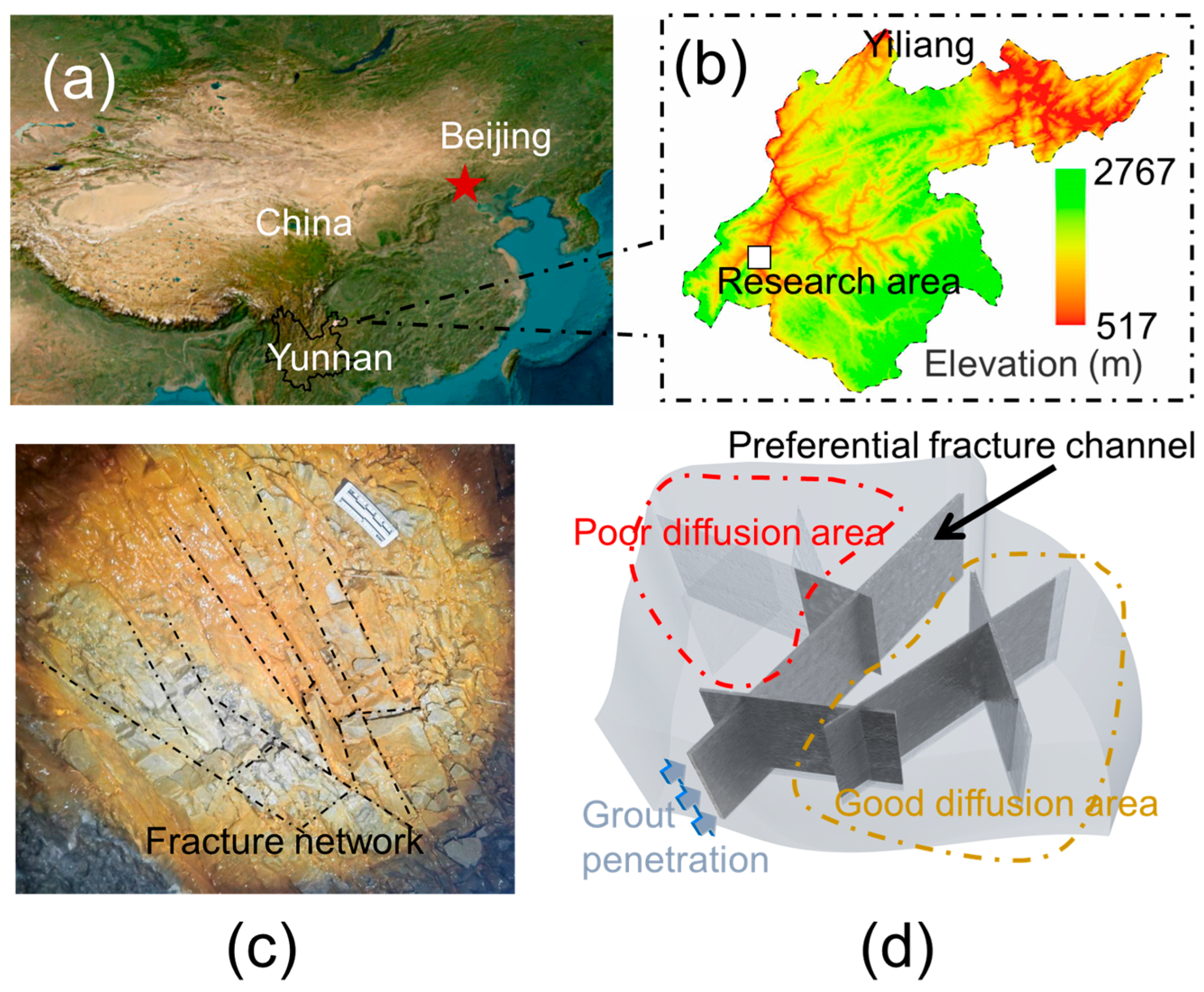
Figure 1. (a,b) Location of the research area. (c) Micro-fracture grouting. (d) Schematic diagram of grout deflection.
Applsci 15 09787 g001
Figure 2. Fracture network model used in experiment.
Applsci 15 09787 g002
Figure 3. (a) Fracture. (b) Filled fracture.
Applsci 15 09787 g003
Figure 4. The variation in viscosity with time. (a) Different concentration of curing agent at 20 °C; (b) relationship among gel time, concentration, and temperature.
Applsci 15 09787 g004
Figure 5. Experimental setup. ① Air compressor; ② computer; ③ data logger; ④ fluid pressure sensors; ⑤ 2D fracture network model; ⑥ grout chambers; ⑦ fluid storage bottle; ⑧ peristaltic pump; ⑨ camera; ⑩ initial water level control device.
Applsci 15 09787 g005
Figure 6. Grout trajectory at the unfilled fracture intersections with various aperture widths.
Applsci 15 09787 g006
Figure 7. Grout propagation length at different unfilled fracture pathway.
Applsci 15 09787 g007
Figure 8. Grout propagation characteristic at the filled fracture intersections with various aperture widths.
Applsci 15 09787 g008
Figure 9. Grout propagation length at different filled fracture pathway.
Applsci 15 09787 g009
Figure 10. Schematic of the filled fracture.
Applsci 15 09787 g010
Figure 11. (a) Numerical simulation model establishment. (b) Grout propagation at the unfilled fracture intersections. (c) Grout propagation at the filled fracture intersections.
Applsci 15 09787 g011
Figure 12. (a) Flowing direction; (b) schematic of grout propagation length in main pathway and branches.
Applsci 15 09787 g012
Figure 13. The ratio of the grout length in the branches and in the main fracture. (a) Experimental results. (b) Numerical simulation results.
Applsci 15 09787 g013
Figure 14. RDM and RUM under different fluid velocity in the (a) unfilled intersections and (b) filled intersections; (c) RUM of different intersections; (d) RDM of different intersections.
Applsci 15 09787 g014
Table 1. Physical properties of mineral oils A and B and mixed oil.
Density (g/cm3)Kinematic Viscosity (mPa·s)Refractive Index
Mineral Oil A0.8125~61.4663
Mineral Oil B0.844101.4397
Mixed Oil0.8238.51.4585
Table 2. Physical properties of fused silica and Chinese standard sand.
Specific Density,
Gs
Maximum Void Ratio,
emax
Minimum Void Ratio,
emin
Hydraulic
Conductivity,
K (10−3 cm/s)
Chinese standard sand2.650.760.516.52~7.00
Fused silica2.210.80.516.39~8.32
Table 3. Permeability of the filled fractures.
Fracture Width b (cm)Average Diameter of Filling d (cm)Particle Shape Factors αPorosity ePermeability k (cm2)
10.051.50.33.18 × 10−7
20.051.50.33.26 × 10−7
30.051.50.33.28 × 10−7
Disclaimer/Publisher’s Note: The statements, opinions and data contained in all publications are solely those of the individual author(s) and contributor(s) and not of MDPI and/or the editor(s). MDPI and/or the editor(s) disclaim responsibility for any injury to people or property resulting from any ideas, methods, instructions or products referred to in the content.