Article

Upper Bound Solution for Stability Analysis of Deep Underground Cavities Under the Influence of Varying Saturation

1
Sanya Institute of Hunan University of Science and Technology, Sanya 572024, China
2
School of Resources Environment and Safety Engineering, Hunan University of Science and Technology, Xiangtan 411201, China
*
Author to whom correspondence should be addressed.
Appl. Sci. 2025, 15(17), 9295; https://doi.org/10.3390/app15179295
Submission received: 8 July 2025 / Revised: 5 August 2025 / Accepted: 17 August 2025 / Published: 24 August 2025
(This article belongs to the Special Issue Slope Stability and Earth Retaining Structures—2nd Edition)

Abstract

Featured Application

The results of this research can be applied to the stability evaluation and design of deep chambers under the conditions of rock saturation change and high geostress. By analyzing the effects of saturation, geostress, and Hoek–Brown parameters on the pressure and damage surfaces of the surrounding rock, it provides a theoretical basis for support design and improves the safety and stability of deep underground projects. This study provides important technical support for deep chamber engineering in complex hydrological and high-stress environments.

Abstract

In order to study the influence of rock mechanical behavior under different saturation conditions on the stability of deep caverns, this paper establishes a mechanical model for bottom drum failure in deep chambers based on Pratt’s pressure arch theory and the upper bound theorem of limit analysis, comprehensively considering the effect of rock saturation. An analytical solution for the surrounding rock pressure under the nonlinear Hoek–Brown criterion is derived, and the optimal upper bound solution is obtained. The study systematically investigates the influence of rock saturation, geostress, and Hoek–Brown parameters (GSI, σc0, σc100, mi, D) on the surrounding rock pressure and the characteristics of potential failure surfaces. The results indicate that the surrounding rock pressure exhibits two-stage variation with saturation degree (Sr): when Sr = 0~0.6, the surrounding rock pressure increases significantly, and the growth rate slows and tends to stabilize when Sr exceeds 0.6. Increases in ground stress field parameters (σv, λ) significantly raise the surrounding rock pressure and expand the potential failure zone. Among the Hoek–Brown parameters, increases in GSI, σc0, σc100, and mi enhance the stability of the surrounding rock, while an increase in the disturbance factor D reduces its bearing capacity. The results of this paper can provide theoretical guidance for the stability evaluation of deep underground chambers.

1. Introduction

With the continuous development of mineral resources and the gradual extension of engineering construction to greater depths, deep underground projects are facing more complex geological conditions and environments with higher geostress. When subjected to high geostress, the surrounding rock of the chamber can very easily undergo large deformation, bottom drum damage, and other engineering disasters, which seriously affect the safety and stability of underground engineering [1,2]. At the same time, changes in the saturation level of the rock mass will significantly affect the strength, deformation characteristics, and permeability of the surrounding rock [3,4]. In a high-geostress environment, the increased saturation of the rock mass leads to enhanced water-induced softening, thus significantly reducing the mechanical strength of the surrounding rock. Concurrently, the change in seepage pressure may further exacerbate the risk of bottom drum damage [5,6,7] Consequently, probing into the mechanism of bottom drum damage in deep chambers under varying saturation conditions holds immense theoretical and engineering significance, thereby enhancing the stability of the surrounding rocks in deep engineering [8,9].
Recently, researchers, both domestically and internationally, have conducted extensive studies on the deformation behavior of surrounding rock in underground chambers, ranging from shallow to deep environments, accumulating substantial theoretical and practical results [10,11]. Using the upper bound theorem of limit analysis combined with the virtual power equation and the Hoek–Brown failure criterion, they have analyzed the overlying rock mass and derived failure curves while considering the effect of variable endpoints [12]. For the stability of the shield tunnel face in shallow burial conditions, adaptive finite element limit analysis and slip-line theory were employed to investigate the passive failure mechanism of the tunnel face, proposing a funnel-shaped asymmetric-boundary failure mode [13]. Based on Terzaghi’s failure mode with both linear and nonlinear criteria, a method for calculating surrounding rock pressure in shallow tunnels was developed, and an explicit expression for horizontal Earth pressure was derived [14]. The Monte Carlo method was utilized to calculate failure probabilities, obtaining safety factors and clearances under different safety levels [15]. Additionally, based on the upper bound theorem, a new curved failure mechanism and the nonlinear Hoek–Brown criterion have been employed, considering support pressure. An objective function has been established and optimized using the variational method, and a critical depth expression distinguishing shallow and deep tunnels has been proposed [16]. Existing studies have primarily focused on the stability analysis of surrounding rock in shallow tunnels, with the related theories and methods gradually being refined [17,18].
However, a survey found that chambers with burial depths greater than 2 to 2.5 times the depth of excavation (H > 2–2.5 hp) are generally regarded as deep chambers in China. Compared to shallow tunnels, deep caverns are subjected to higher ground stress, which amplifies unfavorable geological factors and consequently leads to severe deformation and damage of deep underground caverns. Therefore, it is highly important to conduct an in-depth study on the stability of deep underground chambers [19,20]. Based on the theory of functional deformation and the Hoek–Brown criterion, a collapse shape model for tunnel floors was established, and analytical expressions for key failure parameters were derived [21]. Limit analysis was employed to derive the ultimate upper bound solution of the surrounding rock pressure [22]. Using the upper bound theorem and variational calculations, analytical expressions for the collapse surface were obtained, and the influence of rock parameters on collapse surfaces in karst caves was analyzed [23]. Numerical simulations of continuous tunnels were conducted based on an elastoplastic damage model; energy evolution was examined through transient energy indices, strain energy density, and the energy dissipation rate, providing new insights into rock burst and severe squeezing phenomena [24]. A nonlinear generalized Nishihara model with non-stationary parameter creep, combined with ABAQUS, was utilized to investigate the large deformation mechanisms of soft rock [25].
The above study systematically reveals the stability characteristics of shallow and deep chambers through limit analysis and numerical simulation, providing in-depth insight into the mechanical response of the surrounding rock with increasing burial depth and deriving several engineering-relevant conclusions. However, with increasing burial depth, the effects of high geostress become more pronounced, and the influence of rock saturation differences is significant—particularly in weak surrounding rock environments, where deep chambers are more susceptible to floor heave failure. Previous studies have not adequately addressed these issues or considered the combined effects of rock mass saturation and high ground stress. These limitations restrict the accurate prediction and control of deep foundation failure behavior. Therefore, to address these challenges, this paper integrates the effects of high geostress and rock saturation based on Pratt’s pressure arch theory to establish a failure model tailored to deep chambers. Furthermore, it analyzes the mechanisms by which various parameters affect the distribution of surrounding rock pressure and the potential failure surface, providing a theoretical foundation and technical support for the stability of deep underground chambers.

2. Basic Theory

2.1. Upper Limit Theorem Under High-Geostress Action

High geostress is a common phenomenon in deep rock mass. In order to accurately calculate the geostress in deep chambers, the empirical regression model proposed by Kang Hong pu and Yi Binding is usually used, which expresses in detail the quantitative relationship between the burial depth of the chamber and the vertical and horizontal geostress [26,27], and the specific mathematical expressions are as follows:
σ v =   0.0245 H
λ = 129.58 H + 0.60
σ H = λ σ v
where σv and σH represent the vertical and horizontal geopathic stresses, respectively, in MPa; λ is the lateral pressure coefficient, which represents the proportional difference between the horizontal geopathic stresses and the vertical geopathic stresses; and H corresponds to the depth within the chamber m. In this paper, the high geopathic stresses are regarded as the applied loads and are introduced into the upper limit principle of the limit analysis [28] so as to establish a limit analysis model that is highly correlated with the damage features of the deep chambers, and the specific forms are as follows:
σ i j A ε ˙ i j d A A T i S v i d S + F i A v i d A + σ V l i v i d l i i + σ H l j v i d l j
where σ i j is the stress state when damage occurs; ε ˙ i j is the strain state triggered by the plastic flow when damage occurs; T i refers to the force exerted upon surface S of the deformation mechanism; F i is the volumetric force on the plastic flow generated in the plastic region A when damage occurs; v i characterizes the velocity field formed by the plastic flow resulting from damage to the material; and l i and l j represent the horizontal and vertical components of the length of the velocity discontinuity line, respectively.

2.2. Hoek–Brown Destruction Criteria

The Hoek–Brown damage standard is extensively applied in geotechnical engineering [29] and can effectively depict the damage behavior of a rock mass through the expression
σ 1 = σ 3 + σ c ( m b σ 3 / σ c + s ) a
m b = m i e x p G S I 100 28 14 D
s = e x p G S I 100 9 3 D
a = 1 2 + 1 6 e G S I / 15 e 20 / 3
where σ 1 is the maximum effective principal stress of the rock; σ 3 is the minimum effective principal stress of the rock; σ c is the uniaxial compressive strength of the rock; m b , s , and a are dimensionless parameters related to the characteristics of the rock body; m i is the rock body constant; G S I is the geological strength index of the rock body; and D is the disturbance factor of the rock body. The relationship between the cohesive force c t and internal friction angle φ t for the Hoek–Brown damage criterion can be obtained by using the “tangent method” [30]:
c t = c o s φ t 2 m b a 1 s i n φ t 2 s i n φ t a 1 a t a n φ t m b 1 + s i n φ t a m b a 1 sin φ t 2 sin φ t 1 1 a + s m b tan φ t

2.3. Rock Strength and Saturation Relationships

Rock saturation refers to the proportion of water contained inside the rock’s pore volume, a key factor influencing the rock mechanical behavior, which generally weakens as saturation increases [31]. Vásárhelyi B [32] et al. studied various rock types and established a mathematical correlation between saturation levels and uniaxial compressive strength, expressed as follows:
σ c = A 1 + C 1 exp B 1 S r
B 1 = I n 0.1 σ c 0 σ c 100 A 1 = σ c 0 C 1 C 1 = σ c 0 σ c 100 1 e B 1
where σ c is the uniaxial compressive strength of the rock body under different saturation degrees; S r is the saturation degree of the soil body; A 1 , B 1 , and C 1 are the fitting coefficients; σ c 0 is the uniaxial compressive strength under dry conditions; and σ c 100 is the uniaxial compressive strength in fully saturated conditions. This study incorporates the uniaxial compressive strength of rock under different saturation levels into the Hoek–Brown strength criterion.

3. Destruction Model

Drawing on the research results of [33,34] this paper constructs an applicable bottom drum damage model for deep chambers and systematically analyzes the stability characteristics of deep chambers subjected to the impact of varying rock saturation, taking into account the impact of variations in rock saturation on the strength of the rock body. As shown in Figure 1, the dimensions of the chamber section are 2b × h. The perimeter rock pressure acts on the top plate, the two gangs, and the bottom plate, which are denoted as q, e, and q′, respectively, and all pressures are expressed in units of megapascals (MPa). The vertical and horizontal ground stresses are expressed as σv and σH, respectively. The side pressure correlation coefficient K is defined as the ratio of the peripheral rock pressure on the two gangs to the pressure on the roof plate, which is e = Kq; the bottom pressure correlation coefficient μ indicates the ratio of the roof pressure to the bottom plate pressure and is expressed as q′ = μq. Here, φ denotes the angle of internal friction within the rock mass, and this represents the angle between the rigid slider discontinuity line and the velocity vector on it, while θ 1 = π / 4 + φ t / 2 , θ2 and θ3 are the angular variable parameters in the damage structure. Since the chamber bottom drum damage model is a symmetrically distributed structure, the left half of the structure is now used as the object of analysis. The top arch collapse block ABO moves downward along the vertical direction with a velocity v0; the left gang block BCDE slides along the chamber sidewall with a velocity v1; the relative velocity between block ABO and block BCDE is v01; and the bottom block DEF slides down the chamber floor in the v2 direction, followed by sliding block BCDE and sliding block DEF with a velocity of v12. The pressure arch BAB′ curve equation expression is f ( x ) = x 2 / b 1 f , with f = σ c / 10 and h a = b 1 / f , where f is Pratt’s coefficient, σc is the uniaxial compressive strength of the rock mass, b1 is the pressure arch half-span, and ha is the arch height.
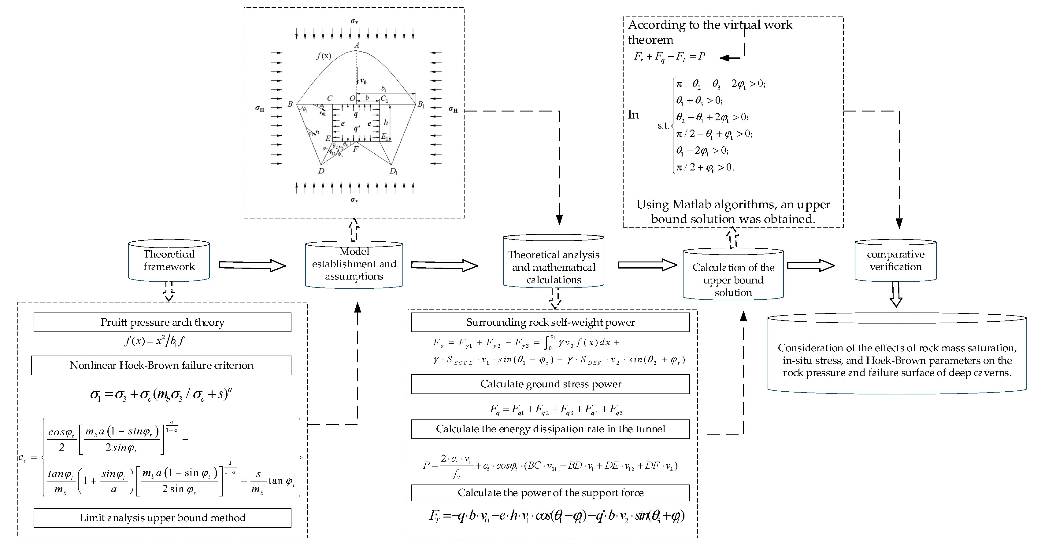
For the stability analysis of deep caverns, the overall research methodology is illustrated in Figure 2, systematically reflecting the complete process from theoretical analysis and calculation to result validation. A theoretical framework and numerical solution approach based on limit analysis are adopted. First, the rock mass is assumed to be an ideal rigid body, simplifying the three-dimensional rock mechanics problem into a two-dimensional plane strain problem to facilitate modeling and computation. The theoretical basis includes Pruitt’s pressure arch theory and the nonlinear Hoek–Brown failure criterion. The limit analysis upper bound theorem is applied to solve for the limit state of the pressure stability of the cavern’s surrounding rock. Based on the model establishment and assumptions, the self-weight power of the surrounding rock, ground stress power, and support force power are calculated, respectively, and a balance equation is established by quantifying these energy relations using the principle of virtual work. Numerical solutions are obtained by MATLAB algorithms to derive the upper bound analytical solution for the stability analysis.

4. Upper Bound Solution

In applying the limit analysis theory to the calculation, this paper makes the following presuppositions: (1) the rock mass is regarded as an ideal rigid body, ignoring the influence of rock joints, cracks, etc., on the damage form; (2) the anisotropy and the change in mechanical strength of the rock mass over time are not considered; (3) the stability problem of the deep chamber is reduced to a two-dimensional plane strain problem.

4.1. Geometric Relationships

From the geometric relationship in Figure 1, we can obtain
D F = b sin θ 2 / sin π θ 2 θ 3
D E = b sin θ 3 / sin π θ 2 θ 3
C D = D E 2 + h 2 2 h D E   cos (   3 π 2 θ 2 )
α = D C E = a r c c o s ( h 2 + C D 2 D E 2 / (   2 h C D )   )
B C = C D sin π 2 θ 1 + α / sin θ 1
B D = C D sin π 2 α / sin θ 1
A B = 0 b 1 1 + f x 2 d x
b 1 = B C + b
From the velocity field relation in Figure 1b, the following is obtained:
v 1 = v 0 sin ( π 2 + φ t ) / sin ( θ 1 2 φ t )
v 01 = v 0 sin (   π 2 θ 1 + φ t ) / sin ( θ 1 2 φ t )
v 12 = v 1 sin ( θ 1 + θ 3 ) / sin ( π θ 2 θ 3 2 φ t )
v 2 = v 1 sin ( θ 2 θ 1 + 2 φ t ) / sin ( π θ 2 θ 3 2 φ t )
In light of the mathematical geometric relationship, the area of each rigid block can be obtained as follows:
S A B O = 0 b 1 f x d x = b 1 2 / 3 f
S B C D E = S B C D + S C D E = 0.5 B C B D sin θ 1 + 0.5 C E D E sin 3 π 2 π θ 2
S D E F = 0.5 D F E F s i n θ 3

4.2. Internal Energy Dissipation Power

When bottom drum damage occurs in a chamber, internal energy dissipation occurs at the velocity discontinuities AB, BC, BD, DE, and DF, and the sum of the dissipated power is expressed as
P = 2 c t v 0 f 2 + c t c o s φ t ( B C v 01 + B D v 1 + D E v 12 + D F v 2 )

4.3. Self-Weight Power of the Surrounding Rock

The enclosing rock self-weight power is given by the work done by the three rigid blocks ABO, BCDE, and DEF, denoted by Fγ1, Fγ2, and Fγ3, respectively.
F γ = F γ 1 + F γ 2 F γ 3 = 0 b 1 γ v 0 f ( x ) d x + γ S B C D E v 1 s i n ( θ 1 φ t ) γ S D E F v 2 s i n ( θ 3 + φ t )

4.4. Geostress Power

The geostress power consists of two parts, the vertical and horizontal geostress, acting on the velocity discontinuity lines AB, BC, BD, DE, and DF, respectively. The geostress power is denoted as Fq1, Fq2, Fq3, Fq4, and Fq5, and then each part of the geostress power is as follows:
F q 1 = σ v v 0 b 1
F q 2 = σ v v 01 B C sin φ t
F q 3 = σ v v 1 sin θ 1 φ t B D cos θ 1 + σ H v 1 cos θ 1 φ t B D sin θ 1
F q 4 = σ v v 12 sin π θ 2 φ t D E sin θ 2 π 2 + σ H v 12 cos π θ 2 φ t D E cos θ 2 π 2
F q 5 = σ v v 2 sin θ 3 + φ t D F cos θ 3 + σ H v 2 cos θ 3 + φ t D F sin θ 3
Therefore, the total ground stress power is calculated as
F q = F q 1 + F q 2 + F q 3 + F q 4 + F q 5

4.5. Support Force Power

The support force does negative work, denoted as FT, whose power is calculated using the following formula:
F T = q b v 0 e h v 1 c o s ( θ 1 φ t ) q b v 2 s i n ( θ 3 + φ t )

4.6. Upper Limit Solution for Perimeter Rock Pressure

According to the upper bound method of limit analysis, in the limit equilibrium state, the power of external forces equals the power dissipated by internal energy. Combining Equations (27), (28), (34) and (35), the analytical solution for the surrounding rock pressure q is derived:
F r + F q + F T = P
q = F γ + F q P b v 0 + K h v 1 sin ( π / 2 θ 1 + φ t ) + μ v 3 cos θ 3 b
s . t . π θ 2 θ 3 2 φ t > 0 ; θ 1 + θ 3 > 0 ; θ 2 θ 1 + 2 φ t > 0 ; π / 2 θ 1 + φ t > 0 ; θ 1 2 φ t > 0 ; π / 2 + φ t > 0 .
The optimal upper bound solution for the chamber enclosure pressure is solved by Equation (37) under the constraints of Equation (38) using the Sequential Quadratic Algorithm in MATLAB R2023a. When the surrounding rock support force is greater than q, the deep-buried chamber remains stable; when the support force is equal to q, the chamber is in a state of limit equilibrium; when the support force is less than q, the chamber undergoes instability and failure.

5. Comparative Verification

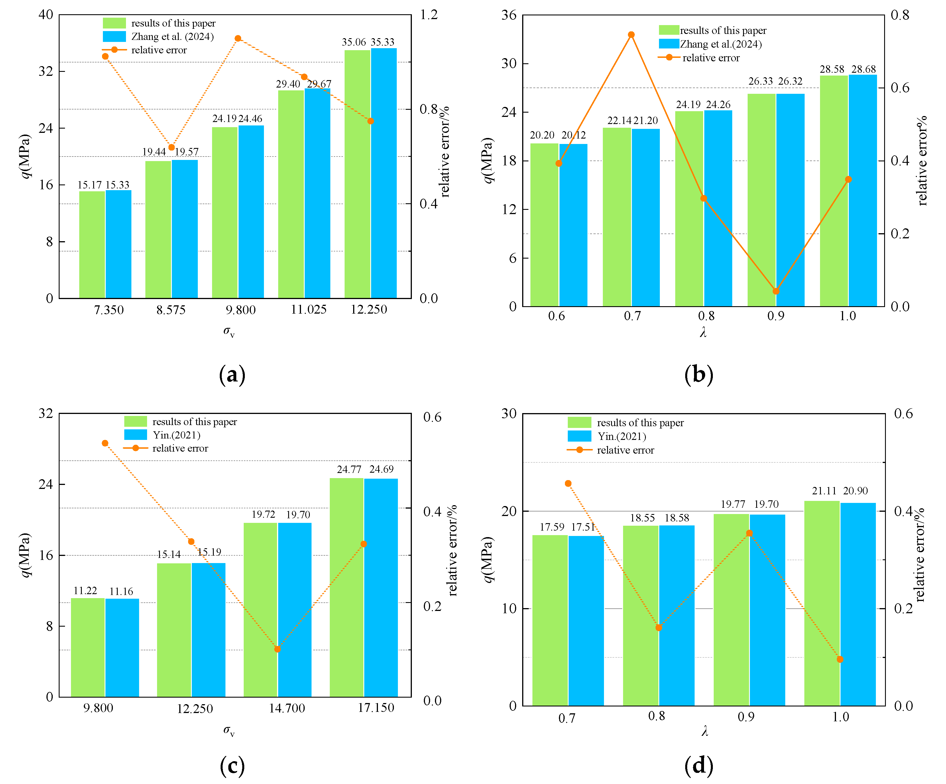
To verify the accuracy of the results of this study, Zhang et al. [35] and Yin [36] used the ultimate upper limit method to calculate the rock pressure when the bottom of a deep cavern was damaged under high-stress conditions, without considering the influence of rock saturation. Therefore, in this paper, the saturation degree Sr = 0, and the other parameters take the same value as in the study [35]. Using the same parameter conditions to assess the effect of bottom drum damage on the surrounding rock pressure of the deep chamber, the results of the comparison are presented in Figure 3. The parameter values are as follows: tunnel size: b × h = 5 × 4 m; GSI = 35; σc = 12 MPa; mi = 16; the lateral pressure correlation coefficient K and bottom pressure correlation coefficient μ are both 1; perturbation factor D = 0; rock mass gravity γ = 23 kN/m3; vertical geopathic stress σv = 7.35~12.25 MPa; and geopathic stress lateral pressure coefficient λ = 0.6~1.0. Analyzing Figure 3a, it can be seen that, for example, with σv = 9.800 Mpa, the results of calculations in the literature and this paper’s calculations are 24.188 MPa and 24.457 MPa, respectively, and their relative errors are 0.73%. Letting λ = 0.8 for this analysis, the literature calculation results and this paper’s calculation results are 24.188 MPa and 24.260 MPa, respectively, and the relative error is 0.35%. When the values of other parameters are consistent with those in Reference [36], analyzing Figure 3c,d, the maximum relative error is only 0.54%. So it can be seen that this paper’s results are highly consistent with the calculation results in the literature, which further verifies the validity of this paper’s results.

6. Analysis of Results

6.1. Effect of Saturation

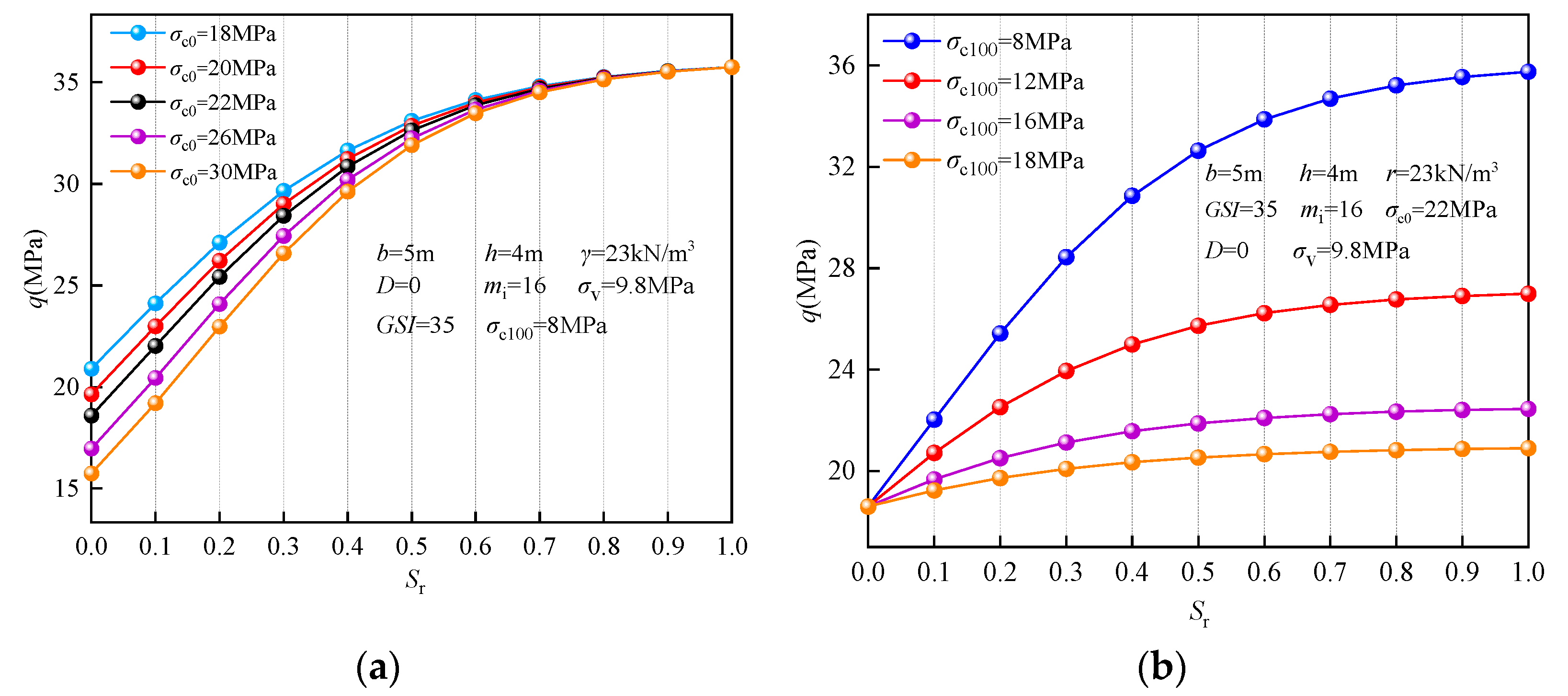
The surrounding rock stability is controlled by multiple factors, and the saturation (Sr), as a key parameter for characterizing the occurrence of pore water in rock mass, significantly affects its mechanical response characteristics. The test data (Figure 4) show that the surrounding rock stress exhibits a nonlinear rise as the saturation Sr increases, and there is a significant difference in the magnitude of this increase.
Δ 1 = q ( S r ) q ( S r = 0 ) q ( S r = 0 ) × 100 % , S r 0.1 , 1 ; Δ 2 = q ( S r ) q ( S r 0.1 ) q ( S r 0.1 ) × 100 % , S r 0.1 , 1 ;
Taking σc0 = 8 MPa, σc100 = 8 MPa, GSI = 35, mi = 16, and σv = 9.8 MPa in Figure 4a, the dimensions of the roadway are b × h = 5 × 4 m, with γ = 23 kN/m3, which represent the conditions for our analysis (see Table 1 for the specific data). When the rock body gradually absorbed water and transitioned from the dry state (Sr = 0) to the fully saturated state (Sr = 1), the surrounding rock pressure gradually increased from 15.747 MPa to 35.754 MPa, with a total increase of 127.05%. If the relative difference in the perimeter rock pressure between two adjacent saturations is 5%, as the limit, and the change below this value can be regarded as negligible, then when the saturation Sr > 0.6, the perimeter rock pressure values between two adjacent saturations and their relative differences are less than 5%, indicating that the increase in the perimeter rock pressure tends to level off thereafter, and this effect can be regarded as weak. Accordingly, it can be inferred that the influence of rock mass saturation on surrounding rock pressure shows obvious two-stage characteristics: in the initial stage (Sr = 0~0.6), the surrounding rock pressure increases rapidly as saturation increases, and when the saturation exceeds the critical value (Sr > 0.6), the pressure growth rate decreases significantly and eventually stabilizes. This is because, when rocks are at a lower saturation level (Sr < 0.6), their mechanical strength decreases as saturation increases, and the lower the saturation level, the greater the decrease in strength. When rocks are at a higher saturation level (Sr > 0.6), their mechanical strength remains largely unchanged as saturation continues to increase. This conclusion corresponds to the threshold given in Reference [37].

6.2. The Influence of Ground Stress

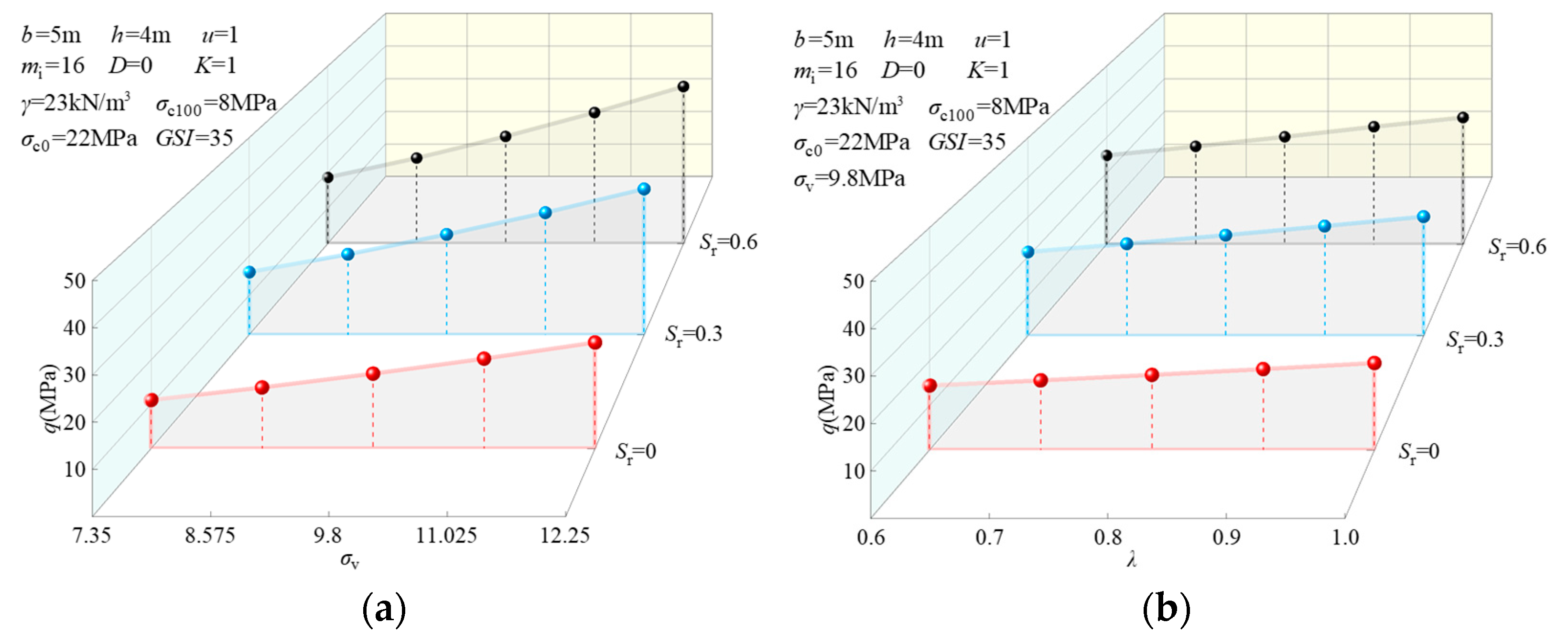
The ground stress field significantly impacts the surrounding rock pressure, with its alterations directly dictating the force conditions and stability of the surrounding rock. Provided that the saturation Sr = 0.3, a rise in the vertical ground stress σv results in a marked rise in the surrounding rock pressure q, and the slope of the curve becomes bigger gradually, suggesting that the effect of the vertical ground stress enhancement on the pressure of the surrounding rock becomes more and more significant. Meanwhile, as the lateral pressure coefficient λ increases, the surrounding rock pressure q also experiences a gradual increase. Each parameter is shown in Figure 5; we can take λ = 0.8 as an example so that σv = 7.35 MPa (at a burial depth of 300 m) can be compared to σv = 12.25 MPa (at a burial depth of 500 m), with the relative error in the surrounding rock pressure reaching 132.65%. Now we can take σv = 9.8 MPa as an example so that λ = 0.6 can be compared with λ =1.0, in which case the relative error in the surrounding rock pressure is 42.14%. It is evident that the vertical ground stress σv and lateral pressure coefficient λ significantly impact the surrounding rock pressure. The stability of the surrounding rock is especially important when considering formations with weak surrounding rock properties and greater burial depths. The calculation method proposed in this paper could provide a strong basis for the rational selection of underground refuge support design parameters.
Figure 6 shows an investigation of how the ground stress field affects the surrounding rock pressure at varying saturation degrees. With an increase in saturation degree Sr, the rise in the surrounding rock pressure q is evident, and the slope of the growth curve becomes progressively steeper, which suggests that a higher saturation degree has a more pronounced effect on increasing the surrounding rock pressure. Taking the vertical ground stress σv = 9.8 MPa and lateral pressure coefficient λ = 0.8 as an example, when the saturation degree is increased from Sr = 0 to Sr = 0.3 and Sr = 0.6, the surrounding rock pressure rises from 16.89 MPa to 25.445 MPa and 30.183 MPa, respectively, which correspond to 43.01% and 78.70%, and this fully explains the significant impact of the saturation degree on the surrounding rock pressure. Therefore, rational consideration of rock saturation variations can lead to more accurate evaluations of the surrounding rock pressure and provide a scientific basis for support design. The method proposed in this study plays an important role in the design of underground chambers, especially under complex hydrological conditions, where saturation changes should be regarded as a key factor in stability assessment. Support design must fully account for load variations under different saturation levels, and, particularly when saturation increases from low to medium–high, anchor bolt length, lining thickness, and reinforcement measures should be adjusted accordingly.

6.3. The Influence of Hoek–Brown Parameters

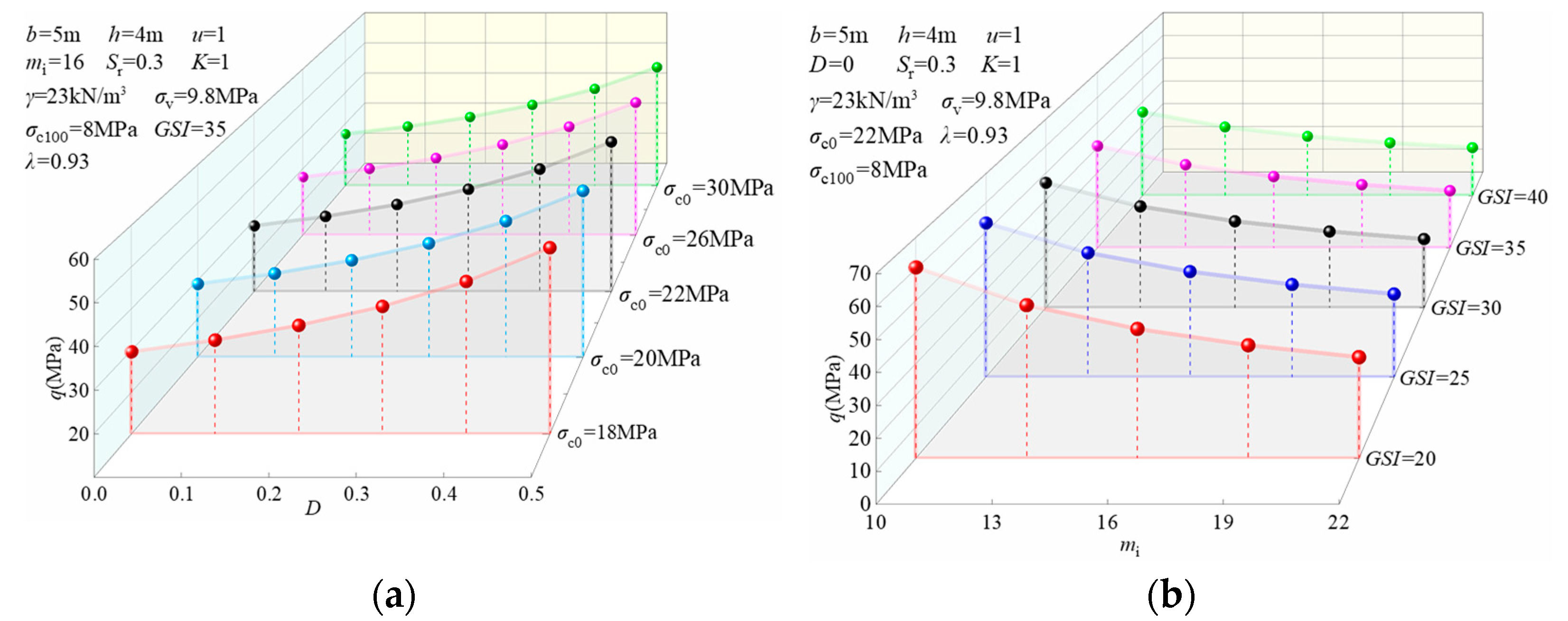
Under saturation condition Sr = 0.3, the influence of the Hoek–Brown intensity parameter on the surrounding rock pressure was analyzed; based on different parameter values, the surrounding rock pressure parameter relationship curve was plotted, as shown in Figure 7.
In Figure 7a, with the gradual increase in σc0, the surrounding rock pressure q gradually decreases, which indicates that the pressure resistance of the surrounding rock increases when the strength of the rock mass is improved; on the contrary, increasing D leads to an elevation in the surrounding rock pressure q, reflecting that disturbance influences reduce the stability level of the surrounding rock. When D = 0.2, the relative error of the perimeter rock pressure is 10.94% when comparing σc0 = 18 MPa and σc0 = 30 MPa. With σc0 = 20 MPa and a comparison of disturbance factors D = 0 (no disturbance) and D = 0.5 (more susceptible to undercutting damage), the relative error of the surrounding rock pressure reaches 83.41%. The preceding analysis indicates that, in dry conditions, the uniaxial compressive strength σc0 and the disturbance factor D exert a substantial influence on the surrounding rock pressure. Particularly when the surrounding rock is softer and subjected to greater disturbance, there is a marked increase in the surrounding rock pressure, consequently heightening the likelihood of chamber damage. For this reason, in this environment, design requirements should be increased to guarantee the safety and stability of the underground chamber.
As shown in Figure 7b, as GSI and mi increase, the surrounding rock pressure q clearly decreases, and the effects of both of these parameters on the surrounding rock pressure are very significant. The increase in the integrity and stability of the rock mass is shown by the increase in GSI and mi, thereby increasing the bearing capacity of the surrounding rock. When taking GSI = 30 as an example and setting the rock constant as mi = 10 and mi = 22 for comparison, the surrounding rock pressure has a relative error of 44.97%; when taking mi = 16 as an example and setting the geological strength index as GSI = 20 and GSI = 40 for comparison, the relative error of the surrounding rock pressure is 47.96%. The above results further demonstrate that GSI and mi exert a profound influence on the surrounding rock pressure, and enhancing them can help to stabilize the rock and reduce the surrounding rock pressure, which in turn improves the design safety.

6.4. Damage Surfaces

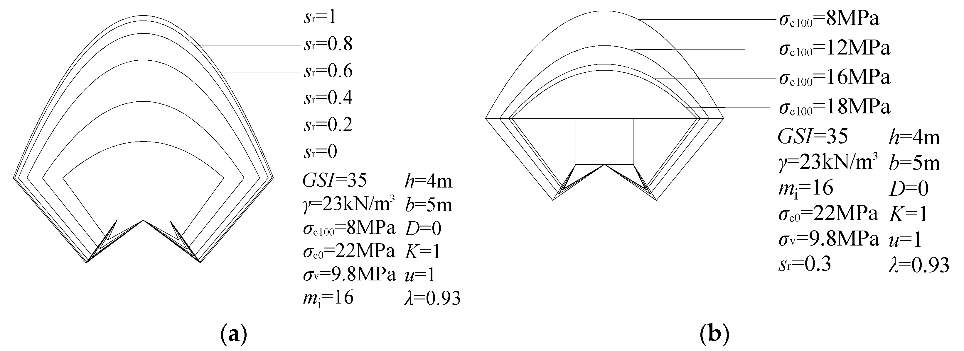
The effect of rock saturation, Sr; the ground stress field; and the Hoek–Brown damage criterion on the extent of the damage surface is shown below. Figure 8a and Table 2 show the variation in damage surfaces in deep chambers for different rock saturations. With σv = 9.8 MPa (at a burial depth of 400 m), λ = 0.93, GSI = 35, mi = 16, σc0 = 22 MPa, σc100 = 8 MPa, and γ = 23 kN/m3, with the saturation, Sr, gradually decreasing from 1 to 0, the depth of the vault decreasing from 15.41 m to 3.46 m, and the width of the slabbing failure decreasing from 9.83 m to 5.12 m. The bottom drum damage length decreases from 4.06 m to 1.88 m, and its relative errors reach as high as 77.55%, 47.91%, and 53.69%, respectively. The data analysis reveals that the saturation degree (Sr) significantly influences the extent of damage to the deep chamber’s surrounding rock, with higher saturation levels resulting in markedly larger failure zones.
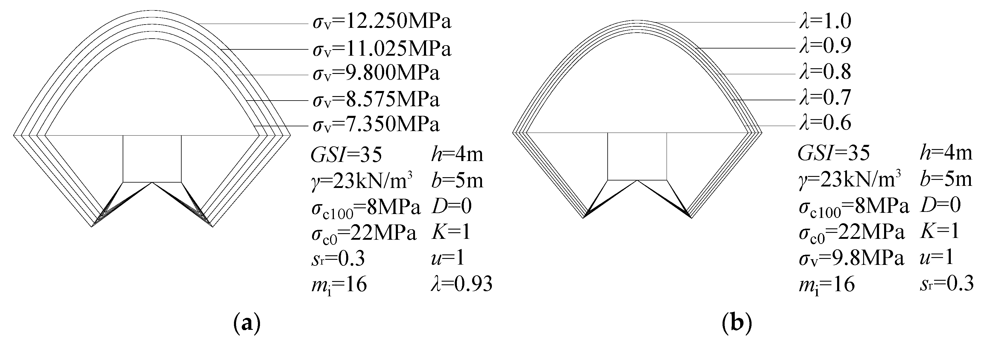
Figure 9 and Table 3 demonstrate the variation in damage surfaces in deep chambers for different vertical ground stress, σv, and lateral pressure coefficient, λ, conditions. Under conditions where other parameters are held constant, the vertical ground stress σv is reduced from 12.25 MPa to 7.35 MPa, the depth of the vault decreases from 17.87 m to 13.48 m, the width of the sheet gang damage surface decreases from 11.62 m to 8.15 m, and the length of the base drum decreases from 4.92 m to 3.26 m, with relative errors of 24.56%, 29.86%, and 33.74%. In addition, as the side pressure coefficient, λ, decreases from 1.0 to 0.6, the depth of the vault decreases from 16.04 m to 14.13 m, the width of the sheet gang damage surface shrinks from 10.17 m to 8.66 m, and the bottom drum damage length decreases from 4.23 m to 3.49 m, with relative errors of 11.93%, 14.84%, and 17.49%, respectively. The above results show that the vertical ground stress, σv, and lateral pressure coefficient, λ, have a significant influence on the damage range of the surrounding rock in deep chambers, and with a decrease in both, the damage range is significantly reduced, which indicates that the stability of the surrounding rock has improved. In view of the high-geostatic-stress environments used in deep engineering, the dynamic change in this parameter must be emphasized for its influence on the damage mechanism.
In Figure 8b and Figure 10, it can be seen that the effect of Hoek–Brown damage criterion parameters on the extent of the damage surface is more significant, and the damage surface’s location gradually expands outward as D increases, whereas the damage surface gradually shrinks inward as GSI, σc0, σc100, and mi increase. This indicates that in the case of a deep cavern having poor-quality surrounding rock or undergoing large engineering disturbances, the development range of the surrounding rock’s plastic zone significantly expands, and the damage area correspondingly increases. In actual projects, it is difficult to accurately determine the anchor support length in the face of large burial depths and complex surrounding rock conditions. By calculating the potential damage range of the refuge, the depth of the vault, the width of the damage surface of the sheet gang, and the length of the bottom drum damage can be clearly defined, which offers a scientific foundation for the rational selection of the anchor support length, thus effectively improving the effect of the support and ensuring the safety of the project.

7. Conclusions

To investigate stability issues for the surrounding rock in deep caverns and tunnels, this study developed a failure model for floor heave in deep caverns based on Prandtl’s stress arch theory, the upper bound theorem of limit analysis, and the nonlinear Hoek–Brown failure criterion. The effects of rock saturation, geostress, and Hoek–Brown parameters on surrounding rock pressure and potential failure surfaces were systematically analyzed. The results indicate the following:
1. This paper comprehensively considers the rock mass stability issues associated with deep cavities and, based on Pritchard’s pressure arch theory, establishes a bottom heave failure model for deep cavities. The study simultaneously considers the effects of geological stress and rock mass saturation and employs the upper bound theorem of limit analysis to solve for the upper bound of rock mass pressure. By comparing the results of this study with those of relevant studies in the literature, it was found that the relative error in rock mass pressure was no more than 1.2%, thereby validating the rationality and effectiveness of the proposed method.
2. Rock saturation has a significant nonlinear effect on the stability of the surrounding rock in deep chambers. As saturation progressively rises from dry conditions (Sr = 0) to fully saturated conditions (Sr = 1), the peak increase in the surrounding rock pressure reaches 127.05%. However, once the saturation degree surpasses 0.6, the rate of increase in the surrounding rock pressure diminishes significantly, indicating that the saturation effect tends to stabilize in the highly saturated region and engineering practices should focus on stability changes in the low-to-medium saturation interval. This provides theoretical and technical references for the design and stability research of deep tunnels, hydropower station caverns, and other engineering projects.
3. Ground stress critically influences the stability of surrounding rock in deep underground caverns. As the burial depth and lateral pressure coefficient increase, the surrounding rock pressure rises significantly, increasing the risk of bottom heave. Accurate evaluation and prediction of ground stress are therefore essential for ensuring structural integrity and longevity. These insights are particularly valuable for optimizing layout and reinforcement strategies in high-ground-stress environments, such as underground mines, gas storage facilities, and transport tunnels.
4. As GSI, σc0, σc100, and mi increase, the extent of damage in deep cavities gradually decreases; however, as saturation Sr, the disturbance coefficient D, vertical stress σv, and the lateral pressure coefficient λ increase, the extent of damage gradually expands, and the influence of these factors on the extent of damage is significant. In actual engineering projects, by calculating the potential damage extent in deep cavities, the support length for the top, sides, and bottom of the cavity can be reasonably determined when using anchor rod support.
Although significant progress has been made in theoretical analysis, certain limitations remain. Rock masses with brittleness and discontinuity have not been considered. In future work, we will use three-dimensional numerical simulation to take these factors into account while incorporating hydraulic–mechanical coupling and seepage effects to further analyze their impact on the bearing capacity of the surrounding rock. This will provide a more comprehensive theoretical basis and technical guidance for the safe design, operation, and maintenance of deep underground engineering projects.

Author Contributions

Conceptualization, D.Z. and S.X.; methodology, J.Z.; software, B.Z. and H.Y.; validation, S.X., Q.L. and A.J.; formal analysis, S.X.; resources, D.Z. All authors have read and agreed to the published version of the manuscript.

Funding

This research was supported by the National Natural Science Foundation of China (52074116). We are deeply grateful for this support.

Institutional Review Board Statement

Not applicable.

Informed Consent Statement

Not applicable.

Data Availability Statement

The original findings presented in this study are included in this article. If you have any further questions, please contact the author.

Conflicts of Interest

The authors declare no conflict of interest.

References

  1. Martin, C.D.; Kaiser, P.K.; Christiansson, R. Stress, instability and design of underground excavations. Int. J. Rock Mech. Min. Sci. 2003, 40, 1027–1047. [Google Scholar] [CrossRef]
  2. Goh, A.T.C.; Zhang, W. Reliability assessment of stability of underground rock caverns. Int. J. Rock Mech. Min. Sci. 2012, 55, 157–163. [Google Scholar] [CrossRef]
  3. Wang, T.; Sun, Q.; Jia, H.L.; Shen, Y.J.; Li, G.Y. Fracture mechanical properties of frozen sandstone at different initial saturation degrees. Rock Mech. Rock Eng. 2022, 55, 3235–3252. [Google Scholar] [CrossRef]
  4. Yin, T.B.; Yin, J.W.; Wu, Y.; Yang, Z.; Liu, X.L.; Zhuang, D.D. Water saturation effects on the mechanical characteristics and fracture evolution of sandstone containing pre-existing flaws. Theor. Appl. Fract. Mech. 2022, 122, 103605. [Google Scholar] [CrossRef]
  5. Ou, X.; Ouyang, L.; Xu, X.; Wang, L. Case study on floor heave failure of highway tunnels in gently inclined coal seam. Eng. Fail. Anal. 2022, 136, 106224. [Google Scholar] [CrossRef]
  6. Feng, J.Q.; Gong, L.; Wang, L.H.; Zhou, P.; Zhang, P.; Li, Y.; Liu, Z.Q. Study on failure mechanism and treatment measures of floor heave of high-speed railway tunnel in the interbedded surrounding rock with high geostress. Eng. Fail. Anal. 2023, 150, 107365. [Google Scholar] [CrossRef]
  7. Wang, M.; Guo, G.L.; Wang, X.Y.; Guo, Y.; Dao, V. Floor heave characteristics and control technology of the roadway driven in deep inclined-strata. Int. J. Min. Sci. Technol. 2015, 25, 267–273. [Google Scholar] [CrossRef]
  8. Wagner, H. Deep mining: A rock engineering challenge. Rock Mech. Rock Eng. 2019, 52, 1417–1446. [Google Scholar] [CrossRef]
  9. An, H.; Mu, X. Contributions to Rock Fracture Induced by High Ground Stress in Deep Mining: A Review. Rock Mech. Rock Eng. 2025, 58, 463–511. [Google Scholar] [CrossRef]
  10. Abdellah, W.R.; Ali, M.A.; Yang, H.S. Studying the effect of some parameters on the stability of shallow tunnels. J. Sustain. Min. 2018, 17, 20–33. [Google Scholar] [CrossRef]
  11. Hernández, Y.Z.; Farfán, A.D.; de Assis, A.P. Three-dimensional analysis of excavation face stability of shallow tunnels. Tunn. Undergr. Space Technol. 2019, 92, 103062. [Google Scholar] [CrossRef]
  12. Liang, J.Y.; Cui, J.; Lu, Y.D.; Shan, Y. Limit Analysis of Shallow Tunnels Collapse Problem with Optimized Solution. Appl. Math. Model. 2022, 109, 98–116. [Google Scholar] [CrossRef]
  13. Yang, Z.W.; Chen, F.Q.; Fang, S.Q. Slip-Line Analysis of Passive Limit Support Pressure for Shallow-Buried Shield Tunnel Face. Int. J. Geomech. 2024, 24, 04024295. [Google Scholar] [CrossRef]
  14. Lei, M.; Peng, L.; Shi, C. Calculation of the surrounding rock pressure on a shallow buried tunnel using linear and nonlinear failure criteria. Autom. Constr. 2014, 37, 191–195. [Google Scholar] [CrossRef]
  15. Zhang, B.; Wang, X.; Zhang, J.S.; Zhang, J.H.; Cheng, H. Safe range analysis of clear distance of twin shallow tunnels based on limit analysis and reliability theory. J. Cent. South Univ. 2018, 25, 196–207. [Google Scholar] [CrossRef]
  16. Yang, X.L.; Huang, F. Collapse mechanism of shallow tunnel based on nonlinear Hoek–Brown failure criterion. Tunn. Undergr. Space Technol. 2011, 26, 686–691. [Google Scholar] [CrossRef]
  17. Zhong, J.H.; Yang, X.L. Two-dimensional face stability analysis in rock masses governed by the Hoek-Brown strength criterion with a new multi-horn mechanism. Int. J. Min. Sci. Technol. 2023, 33, 963–976. [Google Scholar] [CrossRef]
  18. Luo, W.; Xiao, G.Q.; Tao, Z.; Chen, J.Y.; Lu, X.; Wang, H.F. Nonlinear Stability Analysis of Shallow-Buried Bias Tunnel Based on Failure Mode Improvement. Appl. Sci. 2025, 15, 3153. [Google Scholar] [CrossRef]
  19. Zhan, S.Q.; Liu, Y.H.; Xiao, M.; Du, X.W.; Chen, Y.C.; Xing, T.; Kong, C. Numerical Simulation Analysis Method for Rockburst Control in Deeply Buried Caverns. Appl. Sci. 2023, 13, 11197. [Google Scholar] [CrossRef]
  20. Zuo, J.; Wang, J.; Jiang, Y. Macro/meso failure behavior of surrounding rock in deep roadway and its control technology. Int. J. Coal Sci. Technol. 2019, 6, 301–319. [Google Scholar] [CrossRef]
  21. Yang, X.L.; Li, Z.W.; Liu, Z.A.; Xiao, H.B. Collapse analysis of tunnel floor in karst area based on Hoek-Brown rock media. J. Cent. South Univ. 2017, 24, 957–966. [Google Scholar] [CrossRef]
  22. Zhang, D.B.; Zeng, L.H.; Lv, Z.L.; Yu, X.C.; Liu, C.; Jiang, A.M.; Jiang, X.Y.; Li, Q.; Yang, Y.X. Failure Mode of Deep-Buried Rectangular Chamber and Upper Bound Solution of Surrounding Rock Pressure. Mathematics 2024, 13, 69. [Google Scholar] [CrossRef]
  23. Huang, F.; Zhao, L.H.; Ling, T.H.; Yang, X.L. Rock mass collapse mechanism of concealed karst cave beneath deep tunnel. Int. J. Rock Mech. Min. Sci. 2017, 91, 133–138. [Google Scholar] [CrossRef]
  24. Liu, Y.R.; Zhang, R.J.; Hou, S.K.; Zhu, L.; Pang, Z.Y.; Zhuang, W.Y. Investigation of energy evolution process of rock mass during deep tunnel excavation based on elasto-visco plastic damage model and time-dependent energy indices. Acta Geotech. 2025, 20, 1549–1570. [Google Scholar] [CrossRef]
  25. Xu, J.C.; Wen, H.Y.; Sun, C.; Yang, C.B.; Rui, G.R. Numerical simulation of non-stationary parameter creep large deformation mechanism of deep soft rock tunnel. Appl. Sci. 2022, 12, 5311. [Google Scholar] [CrossRef]
  26. Kang, H.P.; Yi, B.D.; Gao, F.Q.; Lu, H.W. Database and characteristics of underground in-situ stress distribution in Chinese coal mines. J. Chin. Coal. Soc. 2019, 44, 23–33. (In Chinese) [Google Scholar]
  27. Yi, B.D. Development and research of in-situ stress parameters database for underground coal mines of China. Saf. Coal Mines 2021, 52, 134–138. (In Chinese) [Google Scholar]
  28. Chen, W.F. Limit Analysis and Soil Plasticity; J Ross Publishing, Inc: Plantation, FL, USA, 2007. [Google Scholar]
  29. Hoek, E.; Brown, E.T. The Hoek–Brown failure criterion and GSI–2018 edition. J. Rock Mech. Geotech. Eng. 2018, 11, 445–463. [Google Scholar] [CrossRef]
  30. Xu, Y.; Li, L.; Zou, J.F. Generalized Hoek-Brown solution of circular tunnel considering effects of axial stress and seepage force. Rock Soil Mech. 2015, 36, 2837–2846+2854. (In Chinese) [Google Scholar]
  31. Gao, Y.F.; Ye, M.; Zhang, F. Three-dimensional analysis of slopes reinforced with piles. J. Cent. South Univ. 2015, 22, 2322–2327. [Google Scholar] [CrossRef]
  32. Vásárhelyi, B.; Ván, P. Influence of water content on the strength of rock. Eng. Geol. 2005, 84, 70–74. [Google Scholar] [CrossRef]
  33. Jiang, B.; Li, S.C.; Wang, Q.; Wang, F.Q.; Zhang, J. Design method of roof anchor cable for deep large section mining roadways based on the upper bound method. Rock Soil Mech. 2017, 38, 2351–2357+2367. (In Chinese) [Google Scholar]
  34. Wang, W.J.; Hou, C.J. Study on mechanical principle and control technique of floor heave in roadway driven along next goaf. Chin. J. Rock Mech. Eng. 2004, 23, 69–74. (In Chinese) [Google Scholar]
  35. Zhang, D.B.; Yin, H.D.; Hu, A.P.; Zhu, Y.N.; Peng, X.J.; Zhang, S.; An, F.X. Analysis on the Stability of Surrounding Rock Damaged by the Floor Drum of Deep Underground Chamber under High In-Situ Stress. J. Disaster Prev. Mitig. Eng. 2024, 44, 660–669. (In Chinese) [Google Scholar]
  36. Yin, H.D. Upper Bound Analysis of Surrounding Rock Pressure and Reliability Study for Roadway Considering Floor Heave Failure. Master’s Thesis, Hunan University of Science and Technology, Xiangtan, China, 2021. (In Chinese). [Google Scholar]
  37. Yang, Z.H.; Yang, X.L.; Zhang, J.H.; Li, Y.X. Upper bound analysis of collapsing area of tunnel face in broken soft rocks under different saturations. J. Cent. South Univ. Sci. Technol. 2015, 46, 2267–2273. (In Chinese) [Google Scholar]
Figure 1. The failure mode of the deep underground chamber of the bottom drum and its corresponding velocity field: (a) failure mode; (b) velocity field.
Applsci 15 09295 g001
Figure 2. Flowchart of research methods and theoretical framework for the stability analysis of deep caverns.
Applsci 15 09295 g002
Figure 3. Comparison of the results of this paper with those of the literature: (a) σv; (b) λ; (c) σv; (d) λ [35,36].
Applsci 15 09295 g003
Figure 4. Influence of saturation on surrounding rock pressure under different conditions: (a) σc0; (b) σc100.
Applsci 15 09295 g004
Figure 5. Influence of geostress field on surrounding rock pressure: (a) σv-λ-q; (b) λ-σv-q.
Applsci 15 09295 g005
Figure 6. Effect of geostress field on surrounding rock pressure under different saturation levels: (a) σv-Sr-q; (b) λ-Sr-q.
Applsci 15 09295 g006
Figure 7. Effect of Hoek–Brown damage criterion on surrounding rock pressure: (a) D-σc0-q; (b) mi-GSI-q.
Applsci 15 09295 g007
Figure 8. Influence of rock saturation on the failure surface: (a) Sr; (b) σc100.
Applsci 15 09295 g008
Figure 9. Influence of geostress field on the failure surface: (a) σv; (b) λ.
Applsci 15 09295 g009
Figure 10. Effect of Hoek–Brown damage criterion parameters on damage surfaces: (a) D; (b) GSI; (c) σc0; (d) mi.
Applsci 15 09295 g010
Table 1. Influence of saturation on surrounding rock pressure.
Serial NumberSrq (MPa)Δ1Δ2
1015.747
20.119.20821.98%21.98%
30.222.97745.91%19.62%
40.326.58568.83%15.7%
50.429.62388.12%11.43%
60.531.908102.63%7.71%
70.633.484112.64%4.94%
80.734.505119.12%3.05%
90.835.14123.15%1.84%
100.935.325124.33%0.53%
111.0 35.754127.05%1.21%
Note: Δ1 represents the relative difference in rock mass pressure between varying degrees of saturation (Sr) and dry conditions (Sr = 0), while Δ2 denotes the relative difference in rock mass pressure between adjacent saturation levels.
Table 2. Arch height, sidewall failure width, and floor heave failure length of deep underground caverns under different rock saturation levels.
SrScope of Damage
Depth of
Vault (m)
Width of
Sheet Gang (m)
Length of
Base Drum (m)
1.015.479.834.06
0.814.919.683.99
0.613.719.333.82
0.411.198.523.44
0.27.267.052.75
03.465.121.88
Table 3. The depth of the deep chamber vault, the failure width of the sheet gang, and the failure length of the bottom drum under different values of σv and λ.
ParametersRetrieve
a Value
Scope of Damage
Depth of
Vault (m)
Width of
Sheet Gang (m)
Length of
Base Drum (m)
σv (MPa)12.25017.8711.624.92
11.02516.8010.774.51
9.80015.719.914.10
8.57514.619.043.68
7.35013.488.153.26
λ1.016.0410.174.23
0.915.579.804.05
0.815.109.433.86
0.714.629.053.68
0.614.138.663.49
Disclaimer/Publisher’s Note: The statements, opinions and data contained in all publications are solely those of the individual author(s) and contributor(s) and not of MDPI and/or the editor(s). MDPI and/or the editor(s) disclaim responsibility for any injury to people or property resulting from any ideas, methods, instructions or products referred to in the content.