Abstract
Flexible inflatable film wings have many functional advantages that traditional fixed rigid wings do not possess, such as foldability, small size, light weight, convenient storage, transportation, and so on. More and more scholars and engineers are paying attention to flexible inflatable wings, which have gradually become a new hot research topic. However, flexible wings rely on inflation pressure to maintain the shape and rigidity of the skin film, and the inflation pressure has a significant influence on the strain deformation and wing bearing characteristics of flexible wing skin film. Here, based on the flexible mechanics theory and balance principle of flexible inflatable film, a theoretical model of structural deformation and internal inflation pressure was constructed, and finite element simulation analysis under different internal inflation pressure conditions was carried out as well. The results demonstrate that the biaxial deformation of flexible wing skin film is closely related to internal inflation pressure, local size, configuration, and film material properties. However, strain deformation along the wingspan direction is quite distinguishing, skin films work under the condition of biaxial plane deformation, and the strain deformation of the spanning direction is obviously higher than that of the chord direction, which all increases with internal inflation pressure. Therefore, it is necessary to pay more attention to bearing strain deformation characteristics to meet the bearing stiffness requirements, which could effectively provide a theoretical reference for the structural optimization design and inflation scheme setting of flexible inflatable wings.
1. Introduction
Flexible inflatable wings, characterized by their lightweight construction, high folding ratio, and rapid deployment [1,2,3], offer significant advantages for unmanned aerial vehicles (UAVs), high-altitude platforms, and cross-domain aircraft. The core structure, composed of flexible membranes (e.g., TPU or fiber-reinforced composites), maintains an aerodynamic shape and bears loads through internal inflation pressure [4,5]. As a key control parameter, inflation pressure directly governs the biaxial stress state, strain distribution, and structural deformation characteristics of the wing membrane [6,7]. Research demonstrates that the membrane exhibits a typical biaxial stress state under pressure [1,7]. Membrane theory and static equilibrium models indicate that increasing inflation pressure significantly elevates spanwise and chord-wise stresses, establishing a defined biaxial stress relationship [1]. Finite element simulations further reveal significant strain non-uniformity; high-curvature regions (e.g., wing root and tip connections) are prone to stress concentration and warpage, while low-curvature regions experience gentler stress gradients [8,9,10].
Inflation pressure modulates overall deformation behavior by altering the membrane’s biaxial stiffness. Insufficient pressure can lead to folds on the compressive surface, causing local stiffness degradation and potential bending–torsional instability; conversely, pressure increases linearly enhance wing bending stiffness and critical buckling load [4,9]. Experimental data confirms this stiffening effect, showing an approximately 250% increase in wing stiffness as pressure rises from 10 kPa to 35 kPa [4].
However, the coupling effects of ambient temperature and aerodynamic loads can exacerbate the nonlinear evolution of strain. Temperature increases alter the membrane’s elastic modulus and amplify biaxial stress via thermal expansion, potentially leading to unbalanced Mises stress distributions, particularly between the root and tip regions [7]. Wind tunnel tests indicate that aerodynamic loads interacting with the internal chamber structure can induce a “wavy” wing surface, potentially triggering flow separation and further intensifying local strain [10,11]. Unlike prior studies investigating thermal effects [7], this work establishes a novel pressure–strain framework for flexible inflatable wings, revealing asymmetric biaxial deformation patterns and providing strain-constrained pressure design rules.
Therefore, while inflation pressure dominantly controls membrane strain and deformation through biaxial stress adjustment, its coupling mechanisms with material properties, environmental factors, and structural design require further quantitative investigation. Flexible inflatable wings, leveraging their high storage ratio, lightweight nature, and excellent damage tolerance, represent key technology for UAVs and space-deployable structures [11,12,13,14]. The core mechanism relies on using internal pressure to control the membrane’s biaxial stress state, thereby influencing strain distribution, dynamic response, and aerodynamic performance. A significant nonlinear relationship exists between inflation pressure and membrane strain. While high-pressure inflation enhances structural stability, it may accelerate material fatigue and increase leakage risk [15]. Conversely, low-pressure environments (e.g., below 25 psi) reduce system mass but can induce membrane wrinkling, local strain concentration, and bending stiffness attenuation [16,17,18].
To address this stability–efficiency trade-off, variable inflation rate control strategies have been proposed. Combining instantaneous optimal control (IOC) with extended position dynamics (XPBD) allows for dynamic adjustment of the inflation rate based on real-time strain. Simulations demonstrate that this approach can reduce kinetic energy deployment by 40%, shorten deployment time by 30%, and significantly suppress oscillations in structures like fourfold tubes [13]. For complex origami-based designs like sun covers, variable-rate inflation reduces stress concentration areas by up to 35%, mitigating tear risks [13]. This offers a promising solution for enhancing dynamic deployment reliability, especially under high dynamic loads encountered during ejection or transonic reentry [11,17].
The biaxial mechanical properties of the membrane material critically determine deformation behavior. Orthotropic high-strength fabrics (e.g., Dyneema® composites) exhibit differences between longitudinal (E1 = 5.45 GPa) and latitudinal (E2 = 5.19 GPa) moduli, leading to non-uniform, post-inflation strain distribution. Crucially, hot-welded joint strength (e.g., 4 N/mm) must satisfy diaphragm design safety margins (e.g., factor of 6.6) to prevent interface peeling [16]. Bio-inspired structural designs offer significant strain distribution improvements; rotating rib arrays inspired by fish dorsal fins can reduce strain energy by 18% via non-uniform pressure distribution, and diaphragm inflatable wings optimized for the section moment of inertia can maintain an aerodynamic shape while reducing operational pressure to 25 psi [16,17,18].
Under extreme conditions, aerodynamic–structural coupling becomes pronounced. During transonic reentry (Ma = 0.8), turbulent wakes induce low-frequency vibrations, while concave skin deformation intensifies aerodynamic heating, elevating surface temperature and pressure by 15–20% compared to static models [17]. For the orbital deployment of space membrane structures, the pressure–strain relationship in microgravity must be modified using iterative membrane property (IMP) algorithms [12]. Furthermore, the inherent “concave-convex” surface of inflatable wings enhances flow adhesion at low Reynolds numbers (Re < 500,000). However, at high Reynolds numbers, incorporating a smooth polymer skin (e.g., silicone elastomer or electroactive polymer) becomes necessary to balance flexible deformation with aerodynamic efficiency [19,20,21].
Therefore, based on the theory of flexible mechanics and the balance principle of flexible inflatable thin skin, this paper constructs a theoretical model of structural deformation and internal inflation pressure and carries out finite element simulation analysis under different internal inflation pressure conditions. It is verified that the biaxial deformation of the flexible wing skin is closely related to the internal inflation pressure, local size, configuration, and film material properties. The strain deformation along the spanwise direction is quite obvious, the flexible skin works under the condition of biaxial deformation, and the strain deformation in the spanwise direction is significantly higher than that in the chord-wise direction, which is proportional to the internal inflation pressure. This study can provide effective theoretical support for the structural optimization design and inflation scheme setting of flexible inflatable wings.
2. Multi-Air Beam Flexible Inflatable Wing Modeling
The multi-air beam flexible inflatable wing, featuring a three-dimensional straight-wing configuration, served as the primary research object. Vent holes integrated into the air beam-type braces facilitated internal gas circulation, ensuring uniform inflation pressure distribution. Once the internal pressure reached the designated threshold, the wing maintained the required aerodynamic profile. The shape of the pressure-stabilized flexible deformable wing is presented in Figure 1.
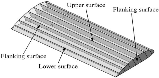
Figure 1.
The three-dimensional shape of the multi-air beam flexible inflatable film wing.
When uninflated, the flexible film wing could be folded and compressed into a compact unit, requiring minimal storage and transportation space. However, as the internal inflation pressure increased, the wing automatically expanded. Through the coupled stretching action of the upper and lower film skins and the internal air beam-type braces, the flexible inflatable wing progressively assumed the desired aerodynamic profile. Typically, the skin film for such wings is an isotropic material or a fiber-reinforced anisotropic composite material. The wing studied in this paper was fabricated from a plain-weave, Vectran, fiber-reinforced, laminated composite film. To facilitate finite element simulation and account for the influence of varying inflation pressures on the film’s strain deformation, the material property parameters of both the flexible skin film and the air beam-type braces are measured at an ambient temperature of 25 °C and consistently presented in Table 1 for the subsequent simulations.

Table 1.
The material parameters of the flexible inflatable wing skin film.
3. Inflation Deformation Modeling and Bearing Deformation Simulation
3.1. Inflatable Flexible Deformation Modeling
This study employs the theory of flexible mechanical films and the principle of pneumatic expansion deformation of flexible wing skin materials, based on a flat straight flexible inflatable wing model [7,8]. The flexible wing skin maintains a three-dimensional deformation state under pressure-stabilized inflation. However, since the skin film is a foldable and stretchable flexible structural material, local deformation of the skin film unit primarily induces biaxial tensile deformation within the film surface, allowing the flexible skin film to be approximated as undergoing in-plane, two-dimensional stress deformation. According to the references [7,8], when we want to study the local deformation analysis of the skin film, only the representative volume element (RVE) deformation needs to be selected for research, and the selected rectangular curved meso-component structural RVE is shown in Figure 2. The flexible skin thin film RVE is subjected to the tension along the biaxial directions of the x-axis and the y-axis to cause biaxial deformation, and the deformation in the z-axis direction has little effect on the load performance and deformation of the flexible skin film; therefore, it could be almost negligible. A similar matrix is composed of a fiber bundle matrix and various isotropic functional films. Since the fiber bundle matrix and various isotropic functional films are all isotropic materials, the fiber bundle matrix and various isotropic functional films could all be simplified as the similar matrix and marked as the matrix during modeling. In a plane stress state, the similar matrix stress in the x and y directions are and , respectively.
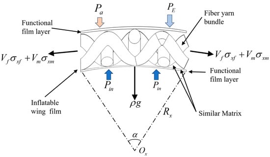
Figure 2.
Deformation and bearing relationship model of flexible film RVE.
Since the biaxial RVE is subjected to tensile loads in two directions, it forms a curved structure within the xoz and yoz planes. The skin film exhibits an arc-shaped profile in each plane, and the corresponding arc radius is Rx in the xoz plane, the corresponding radius of curvature is Kx, and the central angle is α. Similarly, the arc radius is Rz in the yoz plane (orthogonal to the xoz plane), the corresponding radius of curvature is Ky, and the central angle is β [7,8]. The skin film is subjected to biaxial stress and produces tensile deformation. The tensile stresses in both the x-axis and the y-axis are the combined stresses between the fiber bundle and the matrix. Meanwhile, the skin film is also subjected to external/outside atmospheric environmental pressure PE, the aerodynamic pressure load Pa, the internal/inside inflation pressure Pin, and the self-gravity effect. Considering these factors, the equilibrium relationship for the skin film RVE, including self-gravity, can be expressed as follows:
Here, σx and σy denote the internal film stresses in the x- and y-directions, respectively, and t represents the film thickness.
For the inflated wing under pressure stabilization, accounting for stress, geometric parameters, aerodynamic pressure load, and external loads, the following relationship among these variables can be derived [7,8]:
Taking into account the volume stress of the fiber and the matrix, the relationship between the biaxial stress of the flexible film material and the deformation curvature in the x direction and the y direction at the time of formation is as follows [7]:
Here, Kx and Ky (the reciprocals of Rx and Ry) represent the biaxial curvatures.
Usually, the matrix in flexible inflatable membrane material is an isotropic material, and the fiber yarn bundle is an anisotropic material of laminated reinforced warp and weft plain weave. Therefore, in the modeling process, it is necessary to further consider the elastic modulus of the flexible inflatable membrane material along the x direction and the y direction. The biaxial elastic modulus is expressed as Ex and Ey, respectively. When the flexible wing is pressurized, the pressure in the film is equal everywhere, and the change in the inflation radius in the biaxial direction is equal to r. The relationship between the biaxial strain and the elastic modulus Ex and Ey in both directions can be further obtained to characterize the relationship between the volume fraction of the matrix and the fiber yarn in the flexible inflatable film material and the component stress. So, the flexible skin film and the strain–stress relationships between the x-direction and y-direction could be further identified as follows:
By further simplifying the biaxial strain deformation expression of the flexible inflatable wing, the relative radius of curvature of the biaxial deformation of the matrix and the fiber bundle can be set as follows:
Therefore, the above biaxial stress expression (4) can be further simplified. Since the biaxial strain deformation of the flexible inflatable wing film is related to the biaxial stress, and the tensile curvature of the matrix and the fiber bundle along the two biaxial directions and the biaxial material property deformation law can be obtained, the biaxial strain deformation of the flexible inflatable wing film material is as follows:
The flexible inflatable wing skin film RVE is obtained in the bidirectional plane stress state. According to the material mechanical deformation theory, the physical relationship could be further studied between the inflation overpressure deformation characteristics of the flexible skin film material and the internal inflation pressure. Furthermore, the deformation stiffness characteristics of the flexible film can be analyzed according to the deformation conditions.
For the isotropic material Ex = Ey = E, the strain–deformation relationship under the pressure-holding condition of the above biaxial flexible skin film could be further simplified as follows:
Because the excessive deformation of the flexible film (inducing the severe stiffness deformation) seriously affects the aerodynamic performance of the flexible inflated wing and the required load bearing function, it is necessary to study the local deformation stiffness of the flexible skin film, meanwhile, due to the excessive aerodynamic load, which would make the inflatable wing susceptible to wrinkle deformation failure and even cracking. The whole stiffness design needs to comprehensively consider the biaxial deformation limit of the skin film around the inflatable wing, including the flexible film material selection, structural configuration design, connection method, etc. And the strain deformation state and the excessive deformation of the flexible film skin could be verified with the method of the finite element simulation. In order to make the inflatable wing meet the stiffness requirement, according to the strain deformation criterion, the biaxial strain value of the wing skin at any position under the pressure holding state should be required to be smaller than the allowable value [ε] of the skin flexible film material; [ε] is the smaller value of the allowable strain of the fiber yarn bundle [εf] and the allowable strain of the fiber yarn bundle [εm], and the εb limit strain is the smaller value of the ultimate strain of the fiber yarn bundle εfb and the ultimate strain of the fiber yarn bundle εmb. That is,
In the relational formula, εb is the corresponding tensile deformation limit value when the flexible skin film material fails, which could be determined by the biaxial–uniaxial tensile elongation deformation test, and a smaller value could be taken. Here, nf represents the safety factor for the selected film materials.
Considering the comprehensive influencing factors of internal inflation pressure, environmental pressure and aerodynamic load, and the properties of flexible skin film, the strain deformation analysis model and deformation stiffness condition are proposed for the flexible inflatable wing skin film material under biaxial load-bearing conditions. When the strain deformation at a certain position of the inflatable wing skin film material is greater than the allowable strain value of the material, the wing skin film might locally deform excessively to damage or seriously affect the aerodynamic shape so that the flexible inflatable wing would be twisted as a whole. The failure eventually leads to large deformation of the entire wing and thus loses the original aerodynamic performance. A strain–deformation model is proposed for biaxial loading, considering internal pressure, external loads, and material properties. If local strain exceeds [ε], the wing may become distorted, losing aerodynamic function. Thus, inflation pressure must be optimized to maintain deformation within permissible limits.
3.2. Finite Element Simulation
Considering the inconsistency of the deformation and curvature distribution of the matrix and the fiber bundle in the flexible inflatable wing membrane material, the influence of different internal inflation pressure changes on the strain deformation distribution of the flexible inflatable wing membrane material was studied by finite element software ABAQUS 2025. The strain variation characteristics were simulated and analyzed. The established finite element analysis model and load simulation loading are shown in Figure 3.
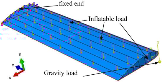
Figure 3.
Flexible inflatable wing inflating pressure loading simulation.
According to the inflation molding principle of flexible inflatable wings, the internal inflation pressure load could be directly applied to the inner surfaces of the upper and lower wing surfaces, the environmental pressure load could be directly applied to the outer surfaces of the upper and lower wing surfaces, and the internal gas pressure is always uniform. Consistently, the brace inside the flexible wing is only subjected to tensile forces and does not require the application of an internal inflation pressure load. Based on Reference [6], the simulated flight aerodynamic load of the upper and lower airfoil of the flexible wing was set to 150 Pa. The different inflation pressure loads and the internal and external environmental pressure loads acting on the flexible wing skin film are all listed in Table 2.
Table 2.
Finite element simulation parameters of the flexible inflatable wing under different inflation pressure conditions.
According to the simulation parameters in Table 2, the different internal and external differential pressure loads were set combined with the finite element simulation model, and then the corresponding strain–deformation characteristics of the skin film could be simulated and calculated out.
Considering that the flexible skin film of the flexible inflatable wing would produce large nonlinear biaxial deformation under the action of internal and external inflation pressure, in the finite element simulation process, the upper and lower wing surfaces use the quadrilateral membrane mesh elements M3D4R, and the grid size is 12. The triangular membrane grid unit M3D3 is selected for the flanking surface, and the grid size is 7. Moreover, the analysis step is performed with the dynamic explicit nonlinear analysis method, and the job type is the full analysis; meanwhile, the stable time increment is about 4.26277 × 10⁻⁷.
4. Results and Discussion
4.1. Analysis of the Strain Deformation of Flexible Wing Film
Different internal inflation pressure loads have a direct influence on the deformation of the flexible inflatable wing skin film, which determines the deformation and overall bearing stiffness characteristics of the inflated wing skin film. The stiffness deformation characteristics would further affect the mechanical properties of the flexible wing subjected to flight aerodynamic loads and the carried functions, which in turn affects the flight performance. In order to compare the strain deformation characteristics of the skin film of the inflatable wing under different inflation pressure loads, combined with the finite element simulation calculation method, differential inflation pressure loads (1500 Pa, 2000 Pa, 2500 Pa) were selected for the comparison calculation. And the strain deformation of the flexible skin film under the influence of different inflation pressure loads (that is, the internal and external inflation pressure difference and the external environmental pressure remains unchanged) calculated by finite element simulation are shown in Figure 4 and Figure 5.
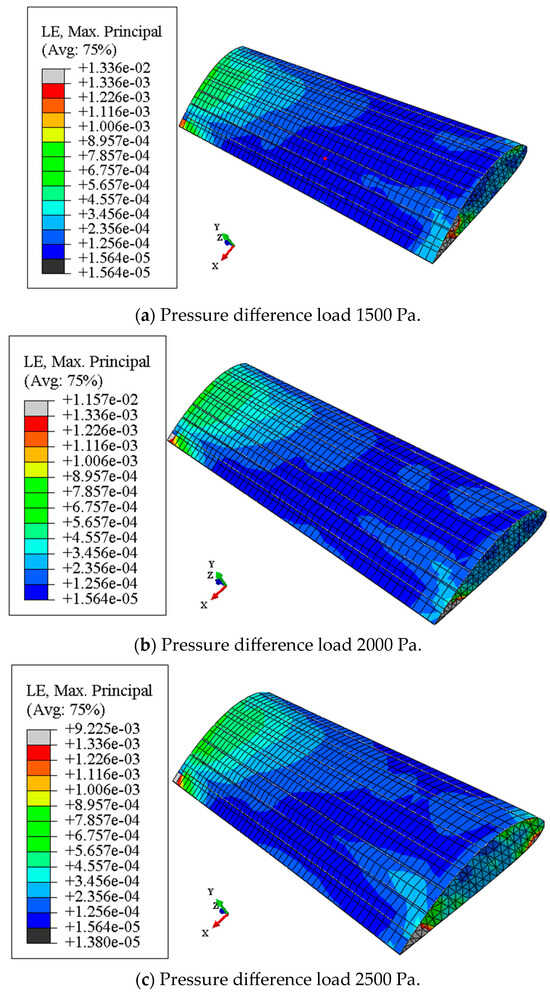
Figure 4.
The strain deformation cloud image of the flexible inflatable wing upper surface.
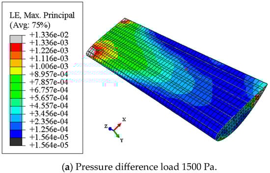
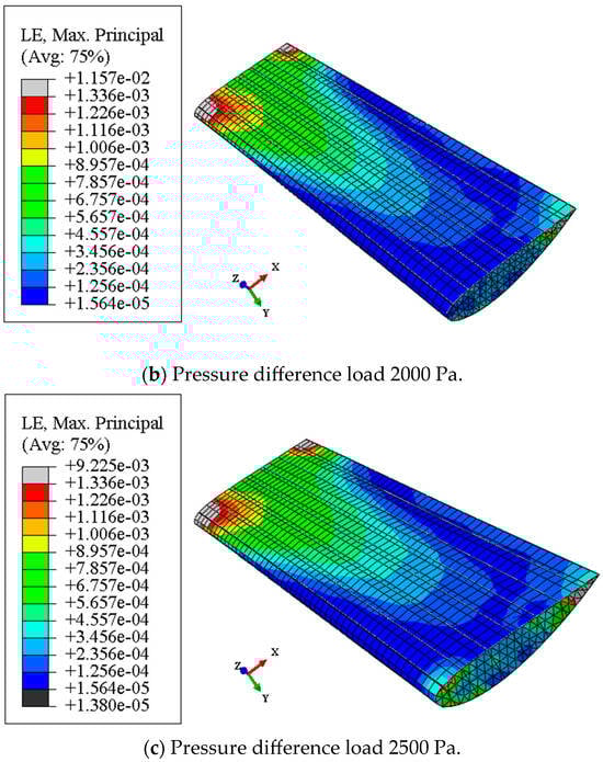
Figure 5.
A strain deformation cloud image of the flexible inflatable wing lower surface.
It can be seen from Figure 4 that for the same flexible wing skin material, the main strain deformation on the upper surfaces of the flexible inflatable wing has a uniform trend along the spanning direction, the strain deformation near the wing root is the largest, the deformation near the wing tip is also great, and the strain deformation in the middle part of the upper wing surface is smaller than that of other areas. Moreover, the strain deformation in the middle part of the leading edge and the trailing edge is obviously much smaller; this is mainly due to the flexible inflatable wing being under the action of the aerodynamic pressure load and the flexible wing producing upward warping deformation, which further alleviates the deformation and bending of the middle part of the wing. Furthermore, as the internal inflation pressure increases, the strain deformation near the wing root of the upper wing also increases gradually, and the strain deformation near the wing tip of the upper wing increases simultaneously. The strain deformation in the middle of the upper wing increases along the chord length, which shows that the surface inflation pressure has a significant effect on the strain deformation of the upper surfaces of the flexible wing, and the changing law shows a positive correlation but not a uniform gradient relationship.
With the increase in the inflation pressure, the gradient of the strain deformation change in the upper surfaces gradually decreases, and the strain deformation of the upper wing skin tends to change over a wide range. The front edge and the trailing edge of the wing surface are strain-deformed. However, as the inflation pressure increases, the change is not obvious, but the overall deformation is quite large. Therefore, the flexible inflatable wing needs to focus on the flexible deformation characteristics of the wing surface. Furthermore, this indicates that within the allowable range of rigidity and strength of the flexible skin film material, if the inflation pressure inside the flexible wing could be appropriately increased, it would be quite beneficial for more uniform strain deformation of the upper wing skin film of the flexible wing, which would also help to alleviate the twist wrinkle problem excessively caused by the aerodynamic load, and also contribute to the distribution of the pressure load on the flexible inflatable skin film.
From Figure 5, with the same flexible wing skin material, the main strain deformation of the lower surfaces of the flexible wing is also basically the same along the spanning direction. The strain of the leading and trailing edge near the wing root has the largest deformation, which gradually decreases along the spanning direction, while the strain deformation in the middle region of the lower wing surface is significantly larger than the leading and trailing edges of the same string length/area. Therefore, this indicates that the lower wing surface of the flexible wing has shear strain deformation along the spanning direction, and the middle part of the lower surfaces is the main area of the strain deformation. Moreover, the strain deformation of the sub-region may affect stiffness deformation and cause the excessive deformation of the flexible wing to become damaged.
Furthermore, with the increase in the internal inflation pressure, the strain deformation near the wing root increases, and the strain deformation near the leading edge and the trailing edge of the wing tip decreases to some extent. This is because the curvature of the film itself is relatively large near the wing tip, and the large inflation pressure helps to relieve the strain deformation near the wing tip. However, as the internal inflation pressure increases, the strain deformation of the lower surfaces gradually increases as a whole and increases synchronously along the spanning and the chord direction of the flexible wing. So, this shows that excessive internal inflation pressure could directly lead to a rapid increase in the strain deformation of the lower surfaces of the flexible wing. And the strain deformation of the lower surfaces is positively correlated with the internal inflation pressure. Then, the increase in the internal inflation pressure also helps to improve the overall bearing stiffness of the flexible wing. However, the strain deformation is also increased synchronously, so the direct influence of the deformation of the lower surfaces of the skin film needs to be considered when increasing the internal inflation pressure load. However, properly increasing the inflation pressure inside the flexible wing is also quite beneficial to more uniform strain deformation of the wing tip of the lower surfaces of the flexible wing, which helps to alleviate the local wrinkling problem generation of the lower wing tip of the flexible skin film caused by the smaller aerodynamic load.
It can be seen from the main strain deformation cloud that the maximum principal strains of the upper and lower surfaces of the flexible wing are all located near the wing root, the strain deformation near the wing root is significantly higher than that of other areas of the flexible inflatable wing, and the strain deformation of the lower surfaces is higher than the strain value at the same position of the upper wing surfaces. The strain deformation of the leading edge and the trailing edge of the upper and lower surfaces is relatively small; this is mainly because the curvature radius of the skin film deformation at this position is quite small, which could verify the theoretical analysis of Formulas (5)–(8), while the minimum principal strain range is only 1.380 × 10⁻⁵~1.564 × 10⁻⁵, which indicates that the minimum principal strain is quite small. And the maximum principal strain range reaches 1.157 × 10⁻²~1.336 × 10⁻², which shows that the range of strain deformation varies greatly for the flexible inflatable wing film under different inflation pressure conditions. Therefore, the relationship between the local maximum strain deformation and the inflation pressure needs to be considered together when the flexible wing is inflated, and the inflation pressure should not exceed the allowable strain deformation range that the flexible skin film could withstand.
4.2. Analysis of Strain Deformation Along the Different Characteristic Line Positions of the Flexible Wing Film
In order to accurately study the strain deformation law of different positions of flexible inflatable wing skin film under the influence of different inflation pressures (1500 Pa, 2000 Pa, 2500 Pa), based on finite element simulation results, the characteristic lines of the upper and lower surfaces of the flexible wing were, respectively, selected as an example. As shown in Figure 6, the spanning characteristic line is in the middle position of the upper and lower surfaces, and the chord characteristic line is in the middle position of the upper surface [6]. Then, the unit nodes on the characteristic line were, respectively, selected, and the spanning direction nodes was selected by a node due to the larger number of adjacent nodes, and the chord-point nodes are continuously selected, and all the node numbers are equally spaced. Consequently, the strain deformation data on the spanning characteristic line of the upper surfaces of the flexible wing under different inflation pressures is listed in Table A1, and the corresponding strain value changing curves are shown in Figure 6. The strain deformation data of the chord characteristic line of the upper wing surfaces of the flexible wing is listed in Table A2, and the corresponding strain changing curves are shown in Figure 7. And the strain deformation data of the lower surfaces of the flexible wing along the spanning characteristic line is listed in Table A3, and the corresponding strain value changing curves are shown in Figure 8.
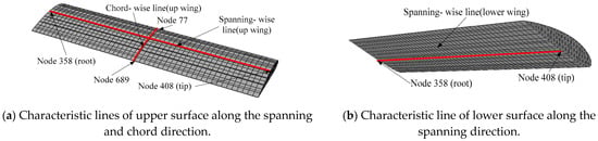
Figure 6.
Characteristic line positions of the upper and lower surfaces of the flexible wing film along the spanning and chord direction [6].
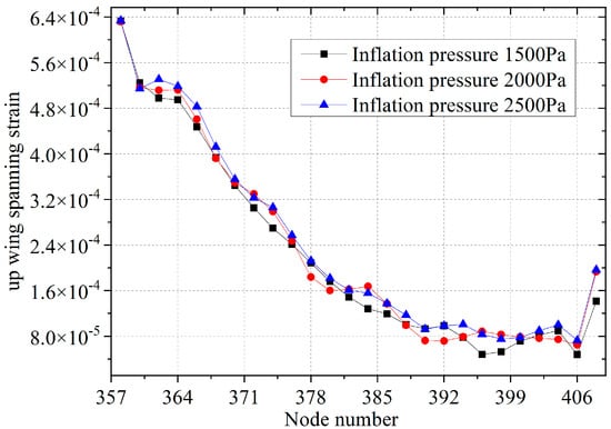
Figure 7.
Strain deformation curves of the upper wing surfaces along the spanning characteristic line under different inflation pressure loads.
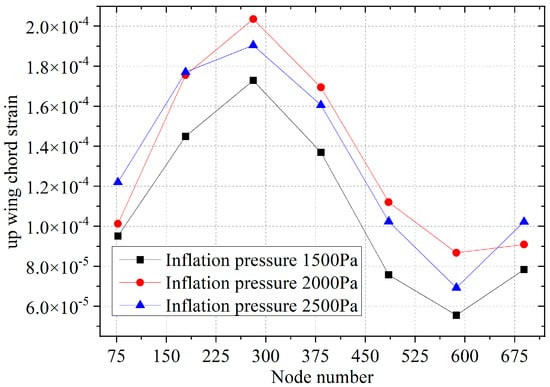
Figure 8.
Strain deformation curves of the upper wing surfaces along the chord-wise characteristic line under different inflation pressure loads.
According to the strain deformation data and the variation curves of the upper surfaces of the flexible inflatable wing in Table A1 and Figure 7, it can be seen that under the same inflation pressure load conditions, the strain deformation of the surface of the flexible wing gradually decreases along the spanning-wise direction, but the jump with a sudden increase occurs near the vicinity of the wing root, which indicates there is a large concentrated load or bending deformation near the wing tip. And as the internal inflation pressure increases, the strain value near the spanning direction of the wing root becomes larger, but the strain deformation in the middle position becomes slightly smaller, and the vicinity of the wing tip continues to become larger. So, the result shows that the strain deformation near the wing root and the wing tip are positively correlated with the internal inflation pressure, and the increase in the internal inflation pressure causes a more severe local deformation of the wing root to induce an excessive fracture failure problem.
The strain deformation in the middle of the surface on the upper wing increases with the increase in the internal inflation pressure, which makes the wing’s warpage deformation decrease, and the overall stiffness becomes larger, and the strain deformation of the wing skin surface is also reduced. Meanwhile, due to the deformation along the chord direction of the flexible wing, the tensile strain deformation of the middle part of the wing exhibits a wave-like change at different positions with the increase in the internal inflation pressure. So, it is verified that the higher inflation pressure is quite beneficial to improve the strain deformation characteristics of the upper surface of the wing skin film, and the upper surface has a larger curvature due to biaxial tensile deformation. Therefore, considering the deformation safety of the flexible wing, it is necessary to consider the biaxial deformation of the surfaces of flexible wings along the spanning and the chord-wise direction together with the internal inflation pressure synchronously.
From the strain deformation data and curves along the chord-wise characteristic line of the upper surfaces of the flexible wing in Table A2 and Figure 8, it can be seen that under the same inflation pressure load, the strain deformation of the upper wing surfaces of the flexible wing changes with the wave-like law. The strain near the leading edge is quite small and then increases toward the middle of the chord-wise direction, and the strain decreases near the trailing edge, which shows that the chord-wise direction of the upper wing surface is mainly subjected to a large pressure load from the middle of the wing surfaces; furthermore, due to the large radius of the curvature of the local structure, the strain deformation is quite small around the leading and the rear edges. Therefore, the flexible wing surface pressure load needs to focus on the strain deformation characteristics of the middle part of the upper surface to prevent excessive deformation failure and damage in this area.
Moreover, as the internal inflation pressure load increases, the internal and external pressure difference loads of the upper surface skin film increase synchronously, the strain value of the upper wing surface increases rapidly along the chord-wise line, and the maximum strain increment value is located in the middle area of the chord-wise direction (up to 2.035 × 10⁻⁴), which indicates that the internal inflation pressure directly affects the strain deformation of the upper wing surface in the chord-wise direction. The larger the internal inflation pressure, the larger the chord-wise strain deformation, but the increase in internal inflation pressure has a very small influence on the strain change in the chord forward and trailing edges. So, the increase in the internal inflation pressure needs to focus on the strain deformation characteristics of the upper chord surface on the wing, and among the allowable strain range, the chord strain deformation change could be ignored along the forward and trailing edges of the upper wing.
According to the strain deformation shown in Table A3 and Figure 9, it can be seen that under the same inflation pressure load, the strain value of the lower surface of the flexible wing increases slightly along the spanning characteristic line near the wing root. Then, the strain deformation value gradually decreases linearly along the wing root towards the wing tip direction, and the maximum strain value is located near the wing root position. Comparing with the Formulas (7)–(8), when designing the lower wing stiffness of the flexible wing, it is quite necessary to focus on the excessive strain deformation of the lower surface near the wing root to prevent failure due to excessive local deformation. And with the increase in the internal inflation pressure, the strain deformation of the lower surfaces gradually increases, but due to the large deformation value of the lower surface, the strain value increment exhibits a wave-like change due to the comprehensive influence of the chord-wise deformation.
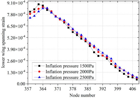
Figure 9.
Strain deformation curves of the lower wing surfaces along the spanning-wise characteristic line under different inflation pressure loads.
However, the strain deformation value near the wing root decreases with the increase in inflation pressure, which indicates that the increase in inflation pressure is beneficial to alleviate the strain deformation near the root of the lower wing surfaces. However, the strain deformation in the middle part of the lower surface shows a wave-like change, and the strain deformation value in the vicinity of the wing tip continues to increase with the increase in the inflation pressure. So, the result shows that the internal inflation pressure load directly leads to an increase in the strain deformation value of the middle part of the lower wing surface and the wing tip position, which affects the distribution of strain change. However, it is quite beneficial to improve the strain deformation near the wing root position of the wing. That is, the increase in inflation pressure could improve the warping deformation near the wing root of the inflatable wing. Moreover, it could also improve the bearing stiffness of the whole flexible inflatable wing, but the maximum strain value near the wing root continues to increase with the increase in the internal inflation pressure. Therefore, the overall stiffness design of the flexible inflatable wing needs to consider the distribution law of the maximum strain deformation near the wing root, which could help ensure that the stiffness of the lower surfaces of the flexible wing is fully deformed to meet the allowable strain requirements.
The off-axis tensile deformation test of flexible inflatable wing skin film is shown in Figure 10. It can be seen from the test results that the tensile deformation and fracture are closely related to the deformation and failure of the internal components of the flexible film. The tensile deformation and fracture failure in the direction of 0° and 90° off axis is mainly controlled by the fiber yarn bundle. The ultimate strain of the fiber yarn bundle directly determines the deformation failure and bearing limit of the flexible inflatable wing skin film, while the matrix deformation has little effect on the deformation failure of the flexible inflatable wing skin film. Therefore, for the tensile deformation in this direction, the tensile deformation of the flexible inflatable wing skin mainly depends on the ultimate deformation value of the fiber yarn bundle. With the increase in tensile deformation, the tensile deformation of the matrix increases significantly, and the matrix cracks first.
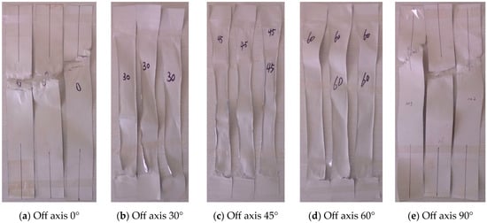
Figure 10.
Experimental study on the axial tensile deformation of the membrane skin of the flexible inflatable wing.
When the crack extends to a certain range, the crack causes the local fracture of the fiber bundle, resulting in the overall tensile deformation and fracture failure of the flexible inflatable membrane skin. Therefore, the tensile deformation and fracture failure in this direction mainly depends on the matrix with large elongation, and the ultimate strain of the matrix directly determines the deformation failure and bearing limit of the flexible inflatable wing skin film, because the matrix cracking leads to the air leakage failure of the flexible inflatable wing skin film, while the fiber deformation has little effect on the deformation failure of the flexible inflatable wing skin film, so for the tensile deformation in this direction, the tensile deformation of the flexible inflatable wing skin mainly depends on the ultimate deformation value of the matrix. Thus, the judgment criterion for the tensile deformation failure of the flexible inflatable wing skin film proposed in this paper is verified. In the design of the flexible inflatable wing film, according to the different load-bearing deformation conditions, the smaller value of the allowable strain of fiber bundle [εf] and the allowable strain of matrix [εm] should be selected for the design strain.
5. Conclusions
The strain deformation of the flexible inflatable wing film under the biaxial bearing condition is physically coupled with the multiple influencing factors such as internal inflation pressure, environmental pressure and aerodynamic load, structure type, and flexible skin film material. And the excessive local deformation of the wing skin film may cause the failure of the whole wing to be invalid or to seriously affect the aerodynamic shape. Therefore, the internal inflation pressure of the flexible inflatable wing needs to focus on the influence of the inflation pressure to ensure the flexible skin film deformation within a reasonable working range.
Considering the deformation safety of the flexible wing, it is quite necessary to consider the biaxial deformation of the surfaces of flexible wing along the spanning and the chord-wise direction together with the internal inflation pressure synchronously. The strain deformation of the upper surface gradually decreases in the span-wise direction, but the strain in the vicinity of the wing root occurs with a sudden change in the jump, and there is a large, concentrated load or bending deformation near the wing tip. The deformation of the upper wing surface in the chord direction shows a wave-like variation law. And with the increase in the internal inflation pressure, the strain deformation near the wing root and the wing tip is positively correlated with the internal inflation pressure, and the increase in the internal inflation pressure may cause the more severe local deformation of the wing root to be excessively large and even induce a new failure problem.
Under the same inflation pressure load conditions, the strain value of the lower surface of the flexible wing increases slightly near the wing root, which is consistent with the constructed theoretical analysis model of biaxial strain deformation. And the change in the strain value of the lower surface is also affected by the deformation of the chord and the spanning biaxial directions. So, while designing the rigidity and strength of the lower surface of the flexible wing, it is quite necessary to consider the maximum strain deformation near the root of the lower wing surfaces to prevent failure due to the excessive local deformation in order to meet the range of allowable strain requirements. However, it is quite beneficial to improve the strain deformation near the wing root position of the wing and improve the bearing stiffness of the whole wing.
The different uniaxial tensile deformation tests of the flexible inflatable wing skin have verified the failure criteria for the tensile deformation of the flexible inflatable wing skin proposed in this paper. While designing flexible inflatable wing membrane skin, the smaller of the allowable strain of the fiber yarn bundle and the allowable strain of the matrix should be selected according to the different load-bearing deformation conditions.
Author Contributions
Conceptualization, L.L. and M.F.; methodology, X.C.; software, L.L.; validation, M.F. and X.C.; formal analysis, L.L.; data curation, M.F.; writing—original draft preparation, L.L.; writing—review and editing, M.F.; visualization, X.C.; supervision, X.C.; funding acquisition, L.L. All authors have read and agreed to the published version of the manuscript.
Funding
This work was sponsored by the National Natural Science Foundation of China (Grant No. 12372085).
Institutional Review Board Statement
Not applicable.
Informed Consent Statement
Not applicable.
Data Availability Statement
The required data can be found in the Appendix A.
Conflicts of Interest
The authors declare no conflict of interest.
Appendix A
Table A1.
Strain deformation data of the upper wing surfaces along the spanning characteristic line under different inflation pressure loads.
Table A1.
Strain deformation data of the upper wing surfaces along the spanning characteristic line under different inflation pressure loads.
| No. | Node No. | Inflation Pressure 1500 Pa | Inflation Pressure 2000 Pa | Inflation Pressure 2500 Pa | Pressure 2000 Pa Increment | Pressure 2500 Pa Increment |
|---|---|---|---|---|---|---|
| 1 | 358 | 6.328 × 10⁻⁴ | 6.322 × 10⁻⁴ | 6.342 × 10⁻⁴ | −6.410 × 10⁻⁷ | 1.328 × 10⁻⁶ |
| 2 | 360 | 5.245 × 10⁻⁴ | 5.164 × 10⁻⁴ | 5.146 × 10⁻⁴ | −8.149 × 10⁻⁶ | −9.949 × 10⁻⁶ |
| 3 | 362 | 4.981 × 10⁻⁴ | 5.118 × 10⁻⁴ | 5.309 × 10⁻⁴ | 1.370 × 10⁻⁵ | 3.277 × 10⁻⁵ |
| 4 | 364 | 4.949 × 10⁻⁴ | 5.122 × 10⁻⁴ | 5.188 × 10⁻⁴ | 1.732 × 10⁻⁵ | 2.389 × 10⁻⁵ |
| 5 | 366 | 4.476 × 10⁻⁴ | 4.608 × 10⁻⁴ | 4.829 × 10⁻⁴ | 1.318 × 10⁻⁵ | 3.532 × 10⁻⁵ |
| 6 | 368 | 3.937 × 10⁻⁴ | 3.923 × 10⁻⁴ | 4.122 × 10⁻⁴ | −1.383 × 10⁻⁶ | 1.845 × 10⁻⁵ |
| 7 | 370 | 3.443 × 10⁻⁴ | 3.493 × 10⁻⁴ | 3.556 × 10⁻⁴ | 4.972 × 10⁻⁶ | 1.133 × 10⁻⁵ |
| 8 | 372 | 3.054 × 10⁻⁴ | 3.299 × 10⁻⁴ | 3.231 × 10⁻⁴ | 2.451 × 10⁻⁵ | 1.772 × 10⁻⁵ |
| 9 | 374 | 2.698 × 10⁻⁴ | 2.991 × 10⁻⁴ | 3.062 × 10⁻⁴ | 2.932 × 10⁻⁵ | 3.646 × 10⁻⁵ |
| 10 | 376 | 2.412 × 10⁻⁴ | 2.473 × 10⁻⁴ | 2.572 × 10⁻⁴ | 6.092 × 10⁻⁶ | 1.599 × 10⁻⁵ |
| 11 | 378 | 2.087 × 10⁻⁴ | 1.839 × 10⁻⁴ | 2.124 × 10⁻⁴ | −2.483 × 10⁻⁵ | 3.667 × 10⁻⁶ |
| 12 | 380 | 1.765 × 10⁻⁴ | 1.606 × 10⁻⁴ | 1.817 × 10⁻⁴ | −1.595 × 10⁻⁵ | 5.204 × 10⁻⁶ |
| 13 | 382 | 1.489 × 10⁻⁴ | 1.626 × 10⁻⁴ | 1.611 × 10⁻⁴ | 1.373 × 10⁻⁵ | 1.224 × 10⁻⁵ |
| 14 | 384 | 1.284 × 10⁻⁴ | 1.676 × 10⁻⁴ | 1.558 × 10⁻⁴ | 3.921 × 10⁻⁵ | 2.746 × 10⁻⁵ |
| 15 | 386 | 1.195 × 10⁻⁴ | 1.373 × 10⁻⁴ | 1.378 × 10⁻⁴ | 1.775 × 10⁻⁵ | 1.825 × 10⁻⁵ |
| 16 | 388 | 1.006 × 10⁻⁴ | 9.953 × 10⁻⁵ | 1.174 × 10⁻⁴ | −1.057 × 10⁻⁶ | 1.678 × 10⁻⁵ |
| 17 | 390 | 9.334 × 10⁻⁵ | 7.256 × 10⁻⁵ | 9.264 × 10⁻⁵ | −2.078 × 10⁻⁵ | −6.978 × 10⁻⁷ |
| 18 | 392 | 9.857 × 10⁻⁵ | 7.198 × 10⁻⁵ | 9.868 × 10⁻⁵ | −2.659 × 10⁻⁵ | 1.149 × 10⁻⁷ |
| 19 | 394 | 7.813 × 10⁻⁵ | 7.927 × 10⁻⁵ | 1.008 × 10⁻⁴ | 1.138 × 10⁻⁶ | 2.271 × 10⁻⁵ |
| 20 | 396 | 4.824 × 10⁻⁵ | 8.857 × 10⁻⁵ | 8.343 × 10⁻⁵ | 4.033 × 10⁻⁵ | 3.519 × 10⁻⁵ |
| 21 | 398 | 5.290 × 10⁻⁵ | 8.301 × 10⁻⁵ | 7.534 × 10⁻⁵ | 3.011 × 10⁻⁵ | 2.245 × 10⁻⁵ |
| 22 | 400 | 7.144 × 10⁻⁵ | 7.917 × 10⁻⁵ | 7.819 × 10⁻⁵ | 7.724 × 10⁻⁶ | 6.743 × 10⁻⁶ |
| 23 | 402 | 8.237 × 10⁻⁵ | 7.674 × 10⁻⁵ | 9.009 × 10⁻⁵ | −5.624 × 10⁻⁶ | 7.717 × 10⁻⁶ |
| 24 | 404 | 8.984 × 10⁻⁵ | 7.490 × 10⁻⁵ | 1.001 × 10⁻⁴ | −1.494 × 10⁻⁵ | 1.030 × 10⁻⁵ |
| 25 | 406 | 4.815 × 10⁻⁵ | 6.516 × 10⁻⁵ | 7.324 × 10⁻⁵ | 1.701 × 10⁻⁵ | 2.509 × 10⁻⁵ |
| 26 | 408 | 1.418 × 10⁻⁴ | 1.933 × 10⁻⁴ | 1.966 × 10⁻⁴ | 5.156 × 10⁻⁵ | 5.485 × 10⁻⁵ |
Table A2.
Strain deformation data of the upper wing surfaces along the chord characteristic line under different inflation pressure loads.
Table A2.
Strain deformation data of the upper wing surfaces along the chord characteristic line under different inflation pressure loads.
| No. | Node No. | Inflation Pressure 1500 Pa | Inflation Pressure 2000 Pa | Inflation Pressure 2500 Pa | Pressure 2000 Pa Increment | Pressure 2500 Pa Increment |
|---|---|---|---|---|---|---|
| 1 | 77 | 9.509 × 10⁻⁵ | 1.012 × 10⁻⁴ | 1.220 × 10⁻⁴ | 6.150 × 10⁻⁶ | 2.690 × 10⁻⁵ |
| 2 | 179 | 1.449 × 10⁻⁴ | 1.756 × 10⁻⁴ | 1.771 × 10⁻⁴ | 3.064 × 10⁻⁵ | 3.214 × 10⁻⁵ |
| 3 | 281 | 1.729 × 10⁻⁴ | 2.035 × 10⁻⁴ | 1.905 × 10⁻⁴ | 3.066 × 10⁻⁵ | 1.758 × 10⁻⁵ |
| 4 | 383 | 1.370 × 10⁻⁴ | 1.695 × 10⁻⁴ | 1.606 × 10⁻⁴ | 3.252 × 10⁻⁵ | 2.364 × 10⁻⁵ |
| 5 | 485 | 7.574 × 10⁻⁵ | 1.120 × 10⁻⁴ | 1.024 × 10⁻⁴ | 3.630 × 10⁻⁵ | 2.667 × 10⁻⁵ |
| 6 | 587 | 5.556 × 10⁻⁵ | 8.677 × 10⁻⁵ | 6.930 × 10⁻⁵ | 3.121 × 10⁻⁵ | 1.374 × 10⁻⁵ |
| 7 | 689 | 7.840 × 10⁻⁵ | 9.092 × 10⁻⁵ | 1.023 × 10⁻⁴ | 1.251 × 10⁻⁵ | 2.387 × 10⁻⁵ |
Table A3.
Strain deformation data of the lower wing surfaces along the spanning-wise characteristic line under different inflation pressure loads.
Table A3.
Strain deformation data of the lower wing surfaces along the spanning-wise characteristic line under different inflation pressure loads.
| No. | Node No. | Inflation Pressure 1500 Pa | Inflation Pressure 2000 Pa | Inflation Pressure 2500 Pa | Pressure 2000 Pa Increment | Pressure 2500 Pa Increment |
|---|---|---|---|---|---|---|
| 1 | 358 | 8.093 × 10⁻⁴ | 7.847 × 10⁻⁴ | 7.404 × 10⁻⁴ | −2.459 × 10⁻⁵ | −6.892 × 10⁻⁵ |
| 2 | 360 | 8.359 × 10⁻⁴ | 8.068 × 10⁻⁴ | 7.620 × 10⁻⁴ | −2.902 × 10⁻⁵ | −7.381 × 10⁻⁵ |
| 3 | 362 | 8.922 × 10⁻⁴ | 8.416 × 10⁻⁴ | 8.118 × 10⁻⁴ | −5.057 × 10⁻⁵ | −8.045 × 10⁻⁵ |
| 4 | 364 | 8.778 × 10⁻⁴ | 8.605 × 10⁻⁴ | 8.468 × 10⁻⁴ | −1.730 × 10⁻⁵ | −3.097 × 10⁻⁵ |
| 5 | 366 | 8.293 × 10⁻⁴ | 8.470 × 10⁻⁴ | 8.497 × 10⁻⁴ | 1.772 × 10⁻⁵ | 2.043 × 10⁻⁵ |
| 6 | 368 | 8.049 × 10⁻⁴ | 8.139 × 10⁻⁴ | 7.985 × 10⁻⁴ | 8.984 × 10⁻⁶ | −6.449 × 10⁻⁶ |
| 7 | 370 | 7.558 × 10⁻⁴ | 7.613 × 10⁻⁴ | 7.532 × 10⁻⁴ | 5.537 × 10⁻⁶ | −2.535 × 10⁻⁶ |
| 8 | 372 | 7.232 × 10⁻⁴ | 7.225 × 10⁻⁴ | 7.334 × 10⁻⁴ | −6.680 × 10⁻⁷ | 1.021 × 10⁻⁵ |
| 9 | 374 | 6.888 × 10⁻⁴ | 6.979 × 10⁻⁴ | 7.124 × 10⁻⁴ | 9.141 × 10⁻⁶ | 2.367 × 10⁻⁵ |
| 10 | 376 | 6.303 × 10⁻⁴ | 6.619 × 10⁻⁴ | 6.691 × 10⁻⁴ | 3.158 × 10⁻⁵ | 3.876 × 10⁻⁵ |
| 11 | 378 | 5.813 × 10⁻⁴ | 6.084 × 10⁻⁴ | 6.167 × 10⁻⁴ | 2.711 × 10⁻⁵ | 3.538 × 10⁻⁵ |
| 12 | 380 | 5.477 × 10⁻⁴ | 5.692 × 10⁻⁴ | 5.750 × 10⁻⁴ | 2.155 × 10⁻⁵ | 2.736 × 10⁻⁵ |
| 13 | 382 | 5.068 × 10⁻⁴ | 5.287 × 10⁻⁴ | 5.481 × 10⁻⁴ | 2.188 × 10⁻⁵ | 4.135 × 10⁻⁵ |
| 14 | 384 | 4.779 × 10⁻⁴ | 4.892 × 10⁻⁴ | 5.060 × 10⁻⁴ | 1.138 × 10⁻⁵ | 2.818 × 10⁻⁵ |
| 15 | 386 | 4.248 × 10⁻⁴ | 4.452 × 10⁻⁴ | 4.569 × 10⁻⁴ | 2.046 × 10⁻⁵ | 3.216 × 10⁻⁵ |
| 16 | 388 | 3.550 × 10⁻⁴ | 4.098 × 10⁻⁴ | 4.265 × 10⁻⁴ | 5.483 × 10⁻⁵ | 7.150 × 10⁻⁵ |
| 17 | 390 | 3.135 × 10⁻⁴ | 3.579 × 10⁻⁴ | 3.832 × 10⁻⁴ | 4.446 × 10⁻⁵ | 6.973 × 10⁻⁵ |
| 18 | 392 | 3.174 × 10⁻⁴ | 3.184 × 10⁻⁴ | 3.475 × 10⁻⁴ | 9.670 × 10⁻⁷ | 3.011 × 10⁻⁵ |
| 19 | 394 | 2.820 × 10⁻⁴ | 2.988 × 10⁻⁴ | 3.140 × 10⁻⁴ | 1.685 × 10⁻⁵ | 3.208 × 10⁻⁵ |
| 20 | 396 | 2.222 × 10⁻⁴ | 2.572 × 10⁻⁴ | 2.830 × 10⁻⁴ | 3.504 × 10⁻⁵ | 6.082 × 10⁻⁵ |
| 21 | 398 | 1.868 × 10⁻⁴ | 2.028 × 10⁻⁴ | 2.249 × 10⁻⁴ | 1.607 × 10⁻⁵ | 3.816 × 10⁻⁵ |
| 22 | 400 | 1.472 × 10⁻⁴ | 1.756 × 10⁻⁴ | 1.827 × 10⁻⁴ | 2.842 × 10⁻⁵ | 3.553 × 10⁻⁵ |
| 23 | 402 | 1.128 × 10⁻⁴ | 1.510 × 10⁻⁴ | 1.525 × 10⁻⁴ | 3.820 × 10⁻⁵ | 3.962 × 10⁻⁵ |
| 24 | 404 | 7.997 × 10⁻⁵ | 1.154 × 10⁻⁴ | 1.228 × 10⁻⁴ | 3.539 × 10⁻⁵ | 4.282 × 10⁻⁵ |
| 25 | 406 | 7.193 × 10⁻⁵ | 9.123 × 10⁻⁵ | 9.911 × 10⁻⁵ | 1.930 × 10⁻⁵ | 2.718 × 10⁻⁵ |
| 26 | 408 | 4.829 × 10⁻⁵ | 6.634 × 10⁻⁵ | 7.394 × 10⁻⁵ | 1.805 × 10⁻⁵ | 2.565 × 10⁻⁵ |
References
- Liao, J.; Wang, N.; Luo, S.B.; Li, J.; Chen, Z.; Ling, L.Y. Design and analysis of inflatable wing of rapid deployment UAV. J. Cent. South Univ. 2022, 53, 1241–1249. [Google Scholar]
- Desai, S.; Schetz, J.A.; Kapania, R.K.; Gupta, R. Wind Tunnel Testing of Tethered Inflatable Wings. J. Aircr. 2024, 61, 1717–1734. [Google Scholar] [CrossRef]
- Ma, N.; Meng, J.H.; Luo, J.Q.; Liu, Q. Optimization of thermal-fluid-structure coupling for variable-span inflatable wings considering case correlation. Aerosp. Sci. Technol. 2024, 153, 109448. [Google Scholar] [CrossRef]
- Mao, Z.B.; Li, Z.P.; Chen, B.; Ge, H.; Xu, Y.; Wang, J.; Chen, X. Prediction method for mechanical properties of inflatable wing and its buckling failure mechanism. Aerosp. Sci. Technol. 2025, 163, 110304. [Google Scholar] [CrossRef]
- Alessandra, L.; Frederico, A.; Afzal, S. A Study on the Surrogate-Based Optimization of Flexible Wings Considering a Flutter Constraint. Appl. Sci. 2024, 14, 2384. [Google Scholar]
- Ma, N.; Liu, L.; Meng, F.; Meng, J. Structural design and modal behaviors analysis of a new swept baffled inflatable wing. Def. Technol. 2023, 24, 382–398. [Google Scholar] [CrossRef]
- Liu, L.; Hu, F.; Jiang, Z.; Liu, T.; Xu, Y. Study on influence of ambient temperature on biaxial stress and strength of flexible inflatable wing film. Results Phys. 2019, 12, 85–93. [Google Scholar] [CrossRef]
- Liu, L.B.; Jiang, Z.Y.; Peng, K.; Hu, F.; Yang, H. Research on Influence of Temperature Variation on Deformation of Inflatable Wing Skin Film. In Proceedings of the 2018 International Conference on Mathematics, Modelling, Simulation and Algorithms (MMSA 2018), Chengdu, China, 25–26 March 2018; Atlantis Press: Amsterdam, The Netherlands, 2018. [Google Scholar]
- Li, B.; Dong, N.; Wang, C.; Zhang, H. Wrinkling and failure behavior research of inflated wing. Chin. J. Aeronaut. 2016, 37, 3044–3053. [Google Scholar]
- Loh, B.; Jamey, J. In-Flight Deployment Dynamics of Inflatable Wings. In Proceedings of the 48th AIAA Aerospace Sciences Meeting Including the New Horizons Forum and Aerospace Exposition, Orlando, FL, USA, 4–7 January 2010. [Google Scholar]
- Dilshad, A.; Muhammed, S.P.; Ajeet, K.; Khan, M. Recent developments of polymer-based skins for morphing wing applications. Polym. Test. 2024, 135, 108463. [Google Scholar]
- Norris, R.K.; Pulliam, W.J. Historical Perspective on Inflatable Wing Structures. In Proceedings of the AIAA Structures, Structural Dynamics, and Materials Conference, Palm Springs, CA, USA, 4–7 May 2009. [Google Scholar]
- Song, Y.Y.; Gandhi, U.; Aris, A. A Baffled Inflatable Wing made from High Performance Textile Materials: Design, Analysis, and Experiments. In Proceedings of the AIAA Scitech 2021 Forum, Virtual Event, 11–15 January 2021. [Google Scholar]
- Wu, J.; Xu, Q.Y.; Zhang, Z.; Hou, A. Aeroelastic characteristics of inflatable reentry vehicle in transonic and supersonic regions. Comput. Fluids 2022, 237, 105338. [Google Scholar] [CrossRef]
- Kong, L.S.; Yang, Y.C.; Wang, J.; Chen, L. Application of a Coupled Eulerian-Lagrangian Approach to the Shape and Force of Scientific Balloons. Appl. Sci. 2025, 15, 1517. [Google Scholar] [CrossRef]
- Cadogan, D.; Smith, T.; Uhelsky, F.; MacKendrick, R. Morphing inflatable wing development for compact package unmanned aerial vehicles. In Proceedings of the American Institute of Aeronautics and Astronautics/American Society of Mechanical Engineers/American Society of Civil Engineers/American Helicopter Society/ASC Structures, Structural Dynamics & Materials Conference, Palm Springs, CA, USA, 19–22 April 2004. [Google Scholar]
- Wei, J.Z.; Hou, S.; Xia, Q.; Tan, H. Structural design and dynamic analysis of an inflatable delta wing. Aerosp. Sci. Technol. 2023, 139, 108371. [Google Scholar] [CrossRef]
- Cadogan, D.; Scarborough, S.; Gleeson, D.; Dixit, A. Recent Development and Test of Inflatable Wings. In Proceedings of the 47th AIAA/ASME/ASCE/AHS/ASC Structures, Structural Dynamics and Materials Conference, Newport, RI, USA, 1–4 May 2006. [Google Scholar]
- Amiy, C.; V, M.; Satish, K. A review on dynamic analysis of membrane based space structures. Adv. Space Res. 2024, 74, 740–763. [Google Scholar]
- Li, N.; Peng, H.J.; Li, F. Instantaneous optimal control of inflatable folded structures. Acta Astronaut. 2022, 195, 52–67. [Google Scholar] [CrossRef]
- Ji, J.J.; Zhu, J.F.; Niu, B.Y.; Lu, J.; Huang, Y. Full-Field Deformation Perception via Flexible Sensing Film Integrating Modified Inverse Finite Element Method. IEEE Trans. Instrum. Meas. 2024, 73, 1–11. [Google Scholar] [CrossRef]
Disclaimer/Publisher’s Note: The statements, opinions and data contained in all publications are solely those of the individual author(s) and contributor(s) and not of MDPI and/or the editor(s). MDPI and/or the editor(s) disclaim responsibility for any injury to people or property resulting from any ideas, methods, instructions or products referred to in the content. |
© 2025 by the authors. Licensee MDPI, Basel, Switzerland. This article is an open access article distributed under the terms and conditions of the Creative Commons Attribution (CC BY) license (https://creativecommons.org/licenses/by/4.0/).