
Effect of Grain Size and Incidence Angle on Erosive Wear of Polyurea Coating


Abstract
1. Introduction
2. Materials and Methods
2.1. Materials
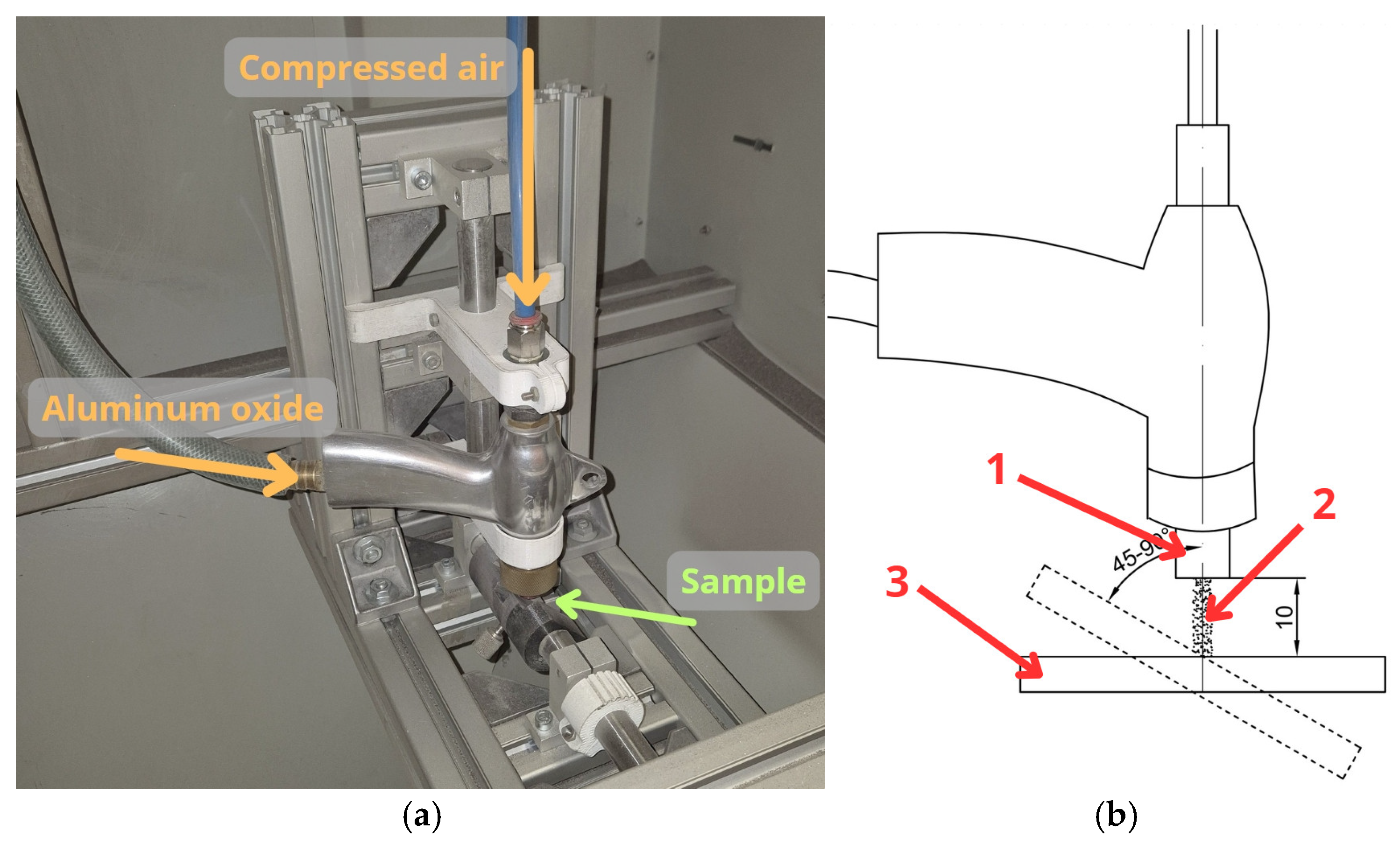
2.2. Methods
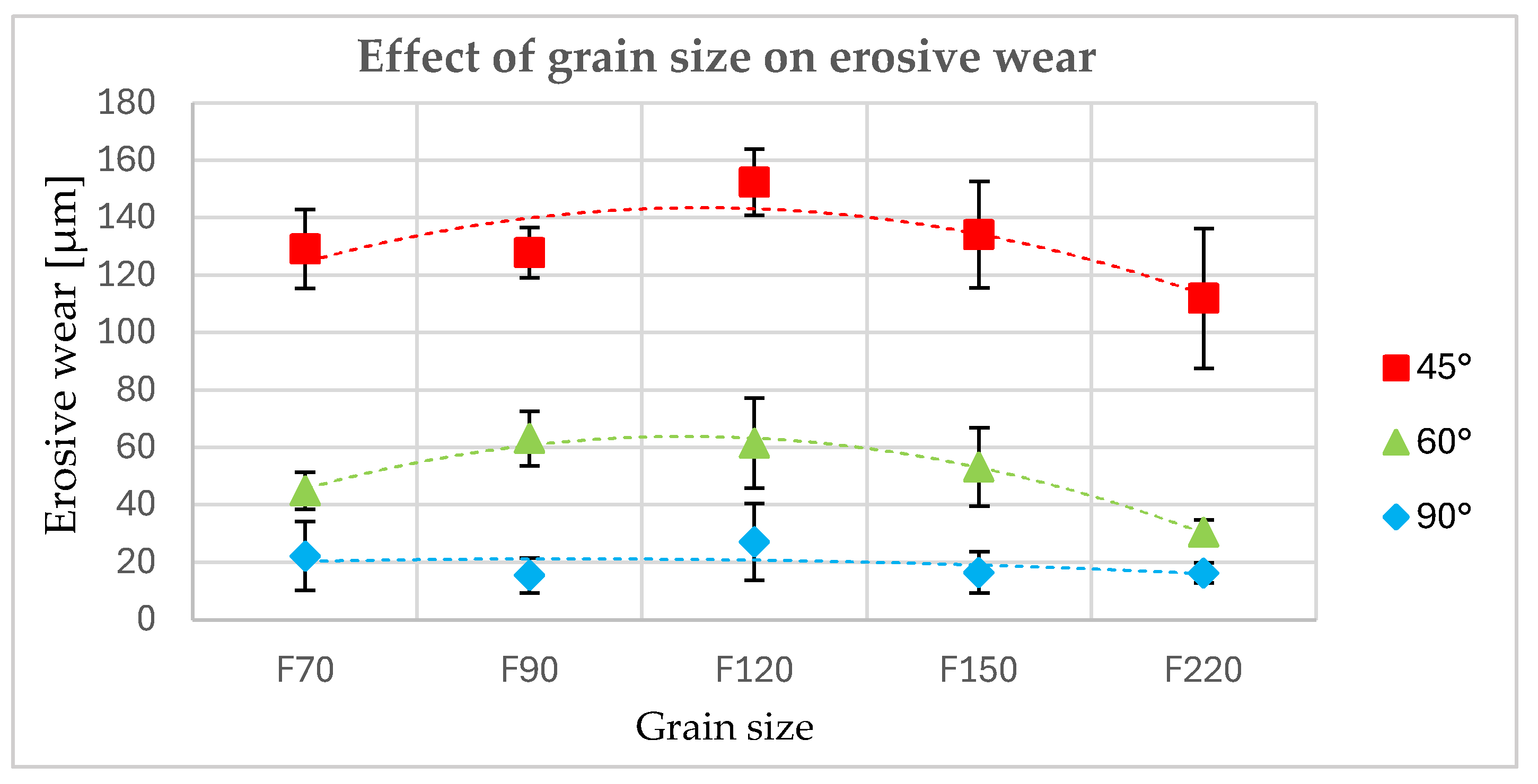
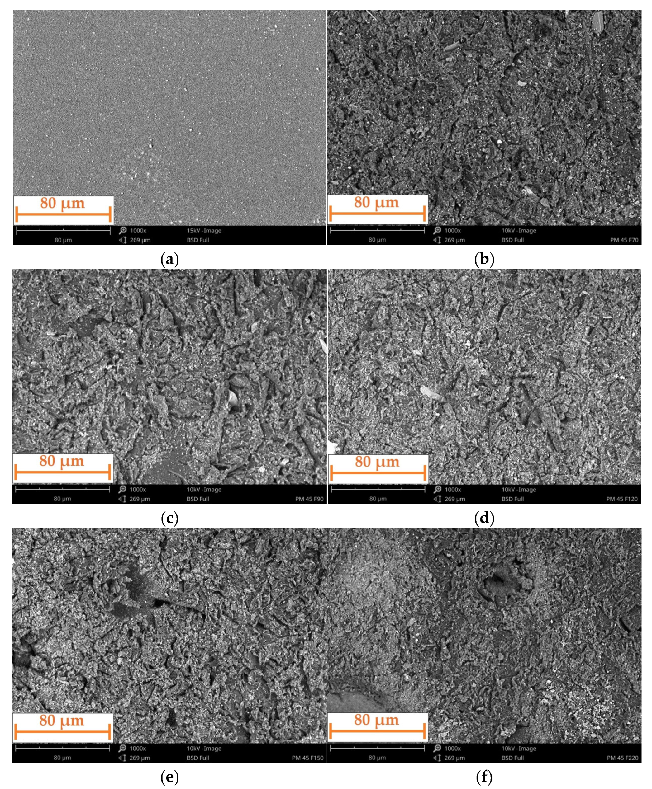
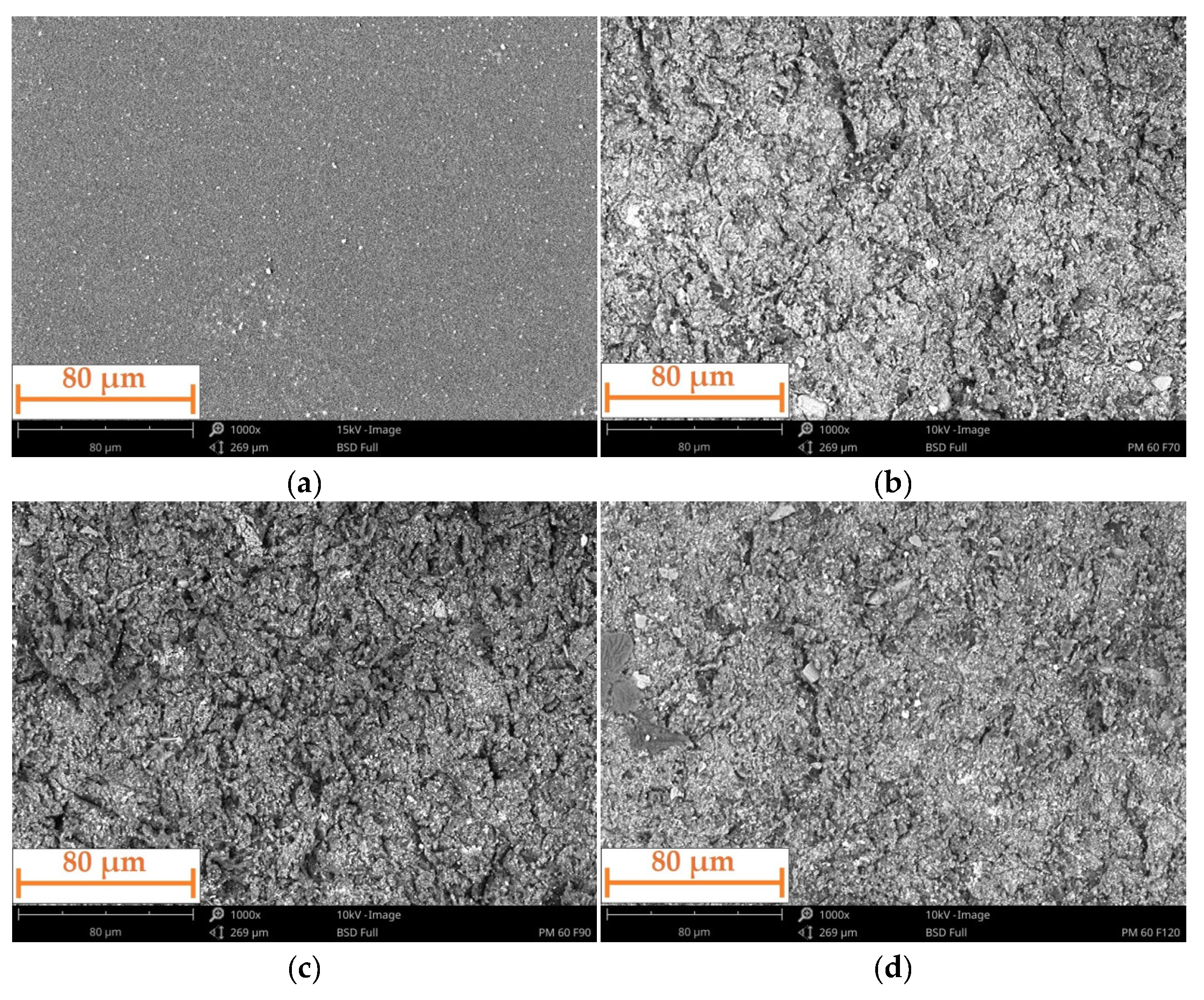
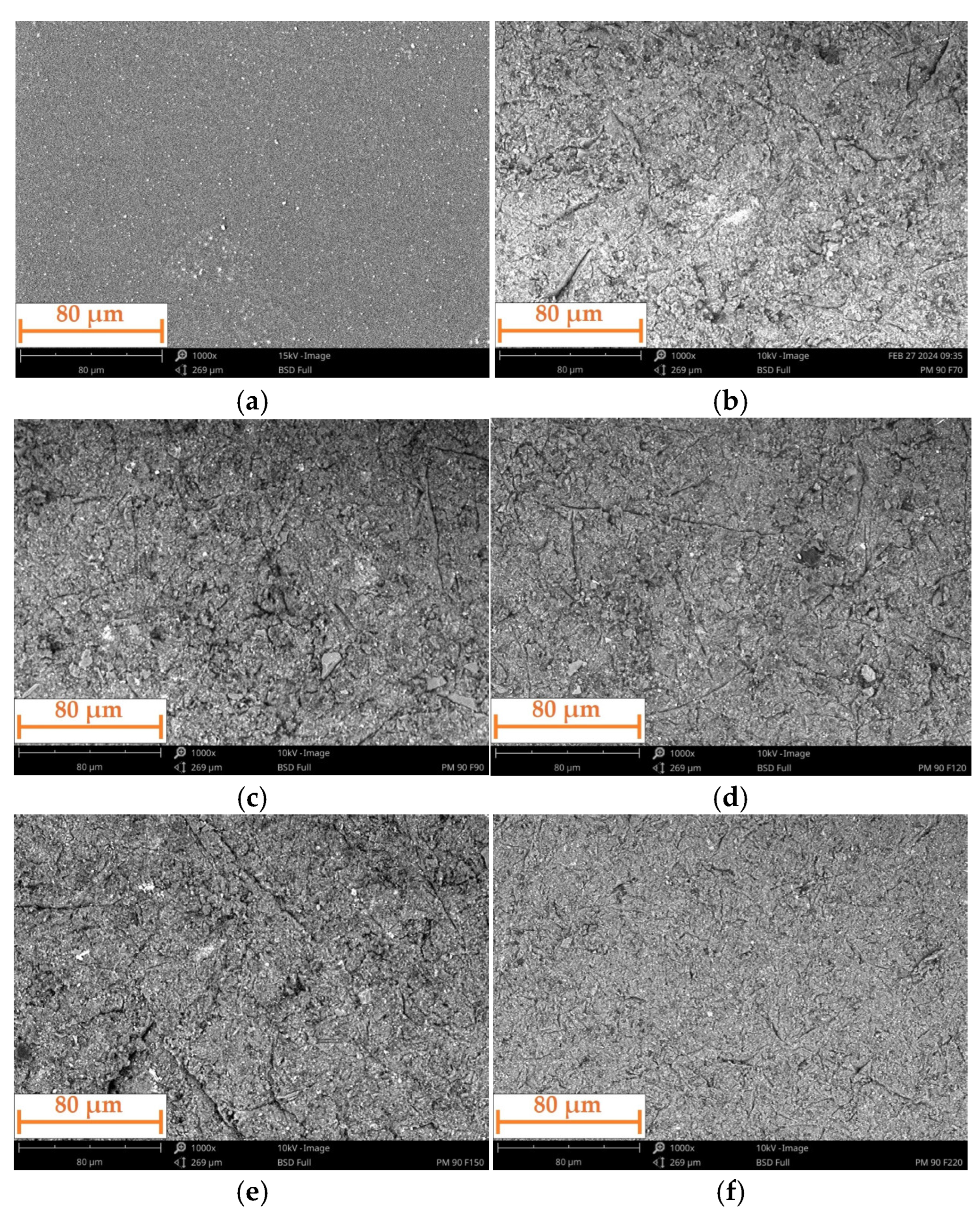
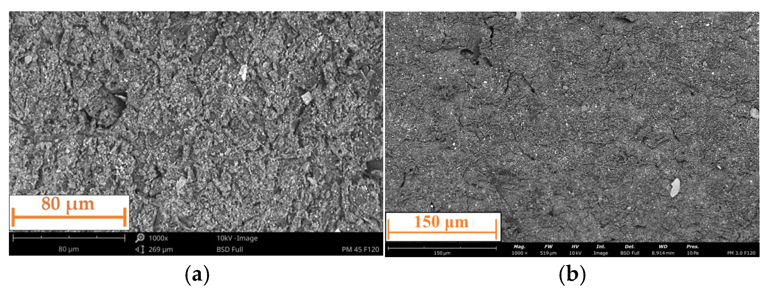
3. Results and Discussion
4. Conclusions
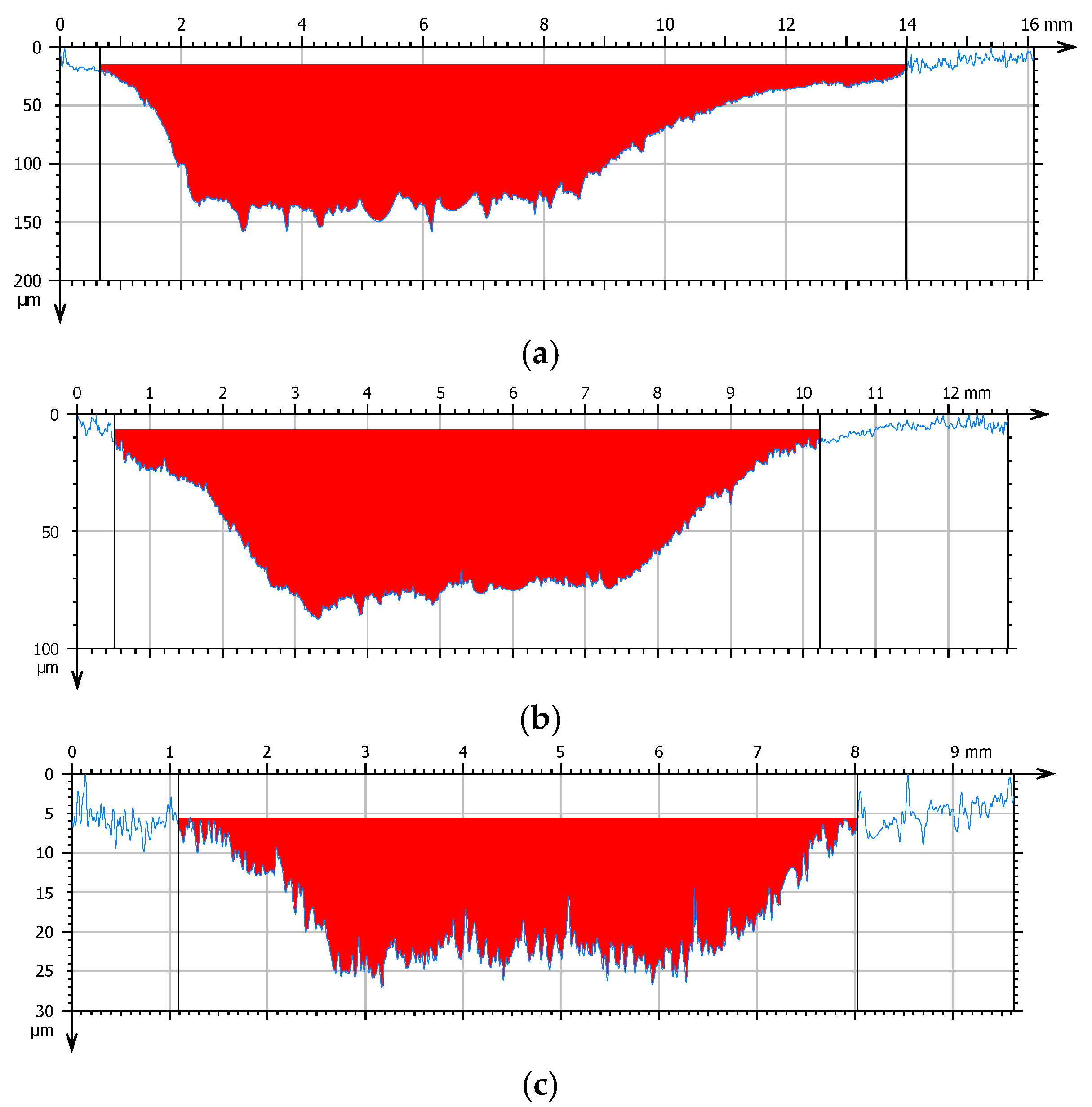
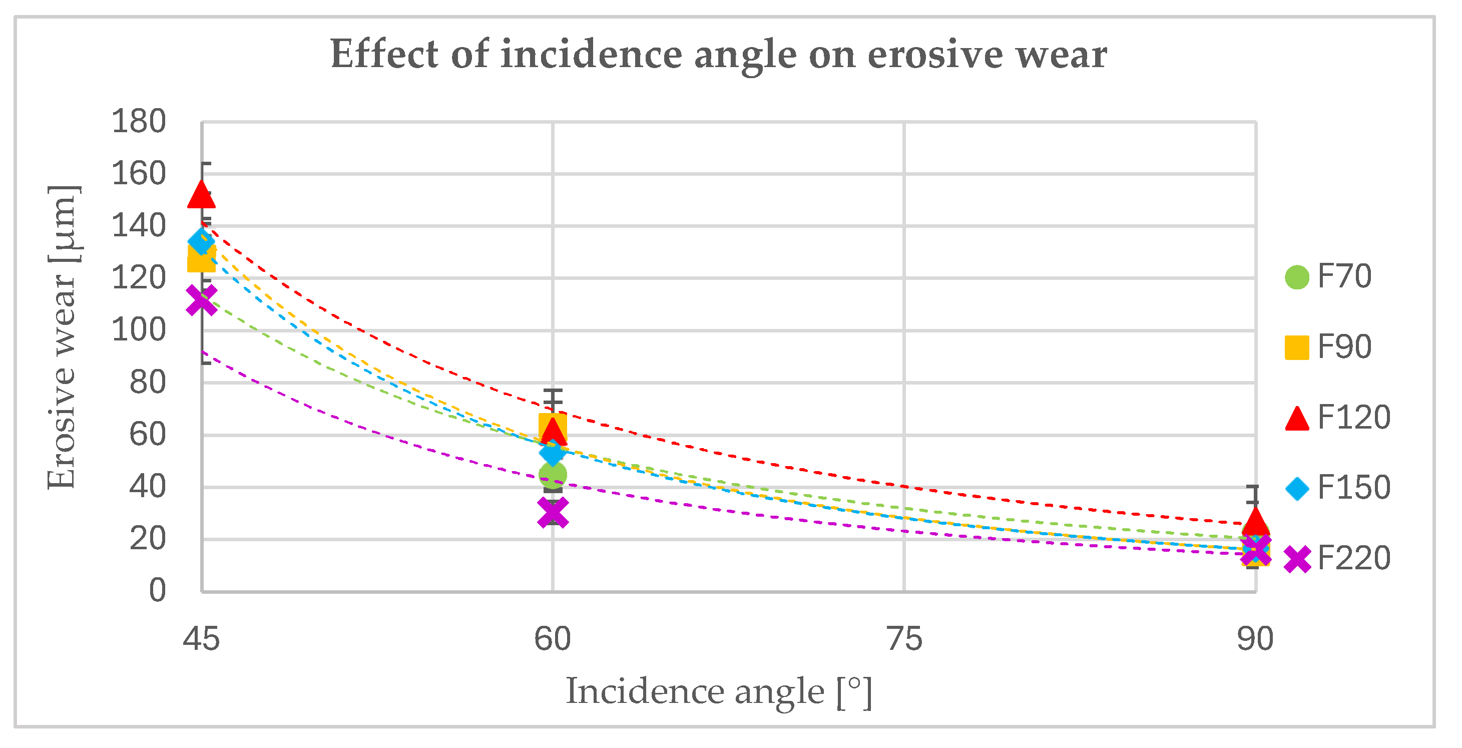
- The incidence angle of the particles has a significant effect on the erosive wear of the polyurea coating. This was observed both quantitatively (the amount of erosive wear) and qualitatively (the nature of the particle interaction). As the incidence angle decreases, the erosive wear increases, and the nature of the interaction between the particles and the coating surface changes. At high angles, this interaction leads to the cracking and chipping off of fragments of the material. At lower angles, there is increasing deformation, resulting in the formation of bruises and the eventual removal of the deformed material by subsequent particles.
- The size of erosive grains has an impact on erosive wear. This is because of the variations in the number of particles of different sizes within a certain volume or mass, and their different kinetic energies and contact areas.
- The incidence angle of the particles also affects the roughness of the coating surface. The higher the incidence angle, the lower the surface roughness. This can be linked to the greater penetration of the particles, which cause deep bruises when eroded at a low angle. No clear pattern was observed regarding the effect of grain size on surface roughness.
Author Contributions
Funding
Institutional Review Board Statement
Informed Consent Statement
Data Availability Statement
Conflicts of Interest
References
- Ürgün, S.; Özsoy, M.İ.; Bora, M.Ö.; Fidan, S. Comparative Evaluation of Solid Particle Erosion Resistance in Milled Carbon Fiber-Reinforced Basalt Fiber Epoxy Composites: Impact of Abrasive Shape Variations. Polym. Compos. 2024, 45, 15356–15379. [Google Scholar] [CrossRef]
- Barczewski, M.; Biedrzycka, K.; Mysiukiewicz, O.; Matykiewicz, D.; Andrzejewski, J.; Kloziński, A.; Szostak, M. Milled Basalt Fibers as Reinforcement for Polyurea Composite Spray Coatings with Improved Thermomechanical Stability and Mechanical Performance. Polimery 2020, 65, 184–195. [Google Scholar] [CrossRef]
- Li, B.; Zhang, J.; Liu, X.; Meng, T. Investigation of a Novel Hydraulic Tunnel Composite Lining with Polyurea Coating Interlayer. Eng. Comput. 2024, 41, 1640–1671. [Google Scholar] [CrossRef]
- Wang, Y.; Ding, L.; Lin, J.; Qiu, X.; Wu, C.; Liu, C.; Tian, Y.; Zhang, R.; Huang, W.; Ma, M. Recent Developments in Polyurea Research for Enhanced Impact Penetration Resistance and Blast Mitigation. Polymers 2024, 16, 440. [Google Scholar] [CrossRef] [PubMed]
- Guo, H.; Sun, Y.; Xiao, Y.; Chen, Y. Investigation of Polyurea Coating Influence on Dynamic Mechanical Properties of Concrete. Structures 2024, 69, 107446. [Google Scholar] [CrossRef]
- Song, J.-H.; Lee, E.-T.; Eun, H.-C. Shear Strength of Reinforced Concrete Columns Retrofitted by Glass Fiber Reinforced Polyurea. Civ. Eng. J. 2020, 6, 1852–1863. [Google Scholar] [CrossRef]
- Toader, G.; Diacon, A.; Axinte, S.M.; Mocanu, A.; Rusen, E. State-of-the-Art Polyurea Coatings: Synthesis Aspects, Structure–Properties Relationship, and Nanocomposites for Ballistic Protection Applications. Polymers 2024, 16, 454. [Google Scholar] [CrossRef]
- Wang, Y.; Jia, X.; Huang, Z.; Yang, C.; Xudong, Z. Polyurea-Coated Ceramic-Aluminum Composite Plates Subjected to Low Velocity Large Fragment Impact. Mater. Today Commun. 2022, 33, 104501. [Google Scholar] [CrossRef]
- Luo, J.; Wang, T.; Sim, C.; Li, Y. Mini-Review of Self-Healing Mechanism and Formulation Optimization of Polyurea Coating. Polymers 2022, 14, 2808. [Google Scholar] [CrossRef]
- Yu, Y.; Li, J.; Xie, Z.; Gao, G.; Sheikhi, M.R.; Li, J. Ballistic Performance of Aluminum Alloy Plates with Polyurea Coatings for High-Speed Train Structures. Compos. Struct. 2025, 351, 118553. [Google Scholar] [CrossRef]
- Zhang, H.; Meng, J.; Cai, L.; Wang, Z.; Tong, G. Polyurea: Evolution, Synthesis, Performance, Modification, and Future Directions. Prog. Org. Coat. 2025, 201, 109127. [Google Scholar] [CrossRef]
- Restasari, A.; Naderizadeh, S.; Kaur, A.; Akutagawa, K.; Busfield, J.; Tan, W. Characterisation of Polyurethane-Urea as Leading-Edge Erosion Resistant Materials of Wind Turbine Blades. IOP Conf. Ser. Earth Environ. Sci. 2024, 1344, 12015. [Google Scholar] [CrossRef]
- Mayer, P.; Lubecki, M.; Stosiak, M.; Robakowska, M. Effects of Surface Preparation on the Adhesion of UV-Aged Polyurethane Coatings. Int. J. Adhes. Adhes. 2022, 117, 103183. [Google Scholar] [CrossRef]
- Karasawa, H.; Shibasaki, H.; Itohiya, G.; Yamashita, S.; Arai, K. Sand Erosion of Polyurethane Coating Materials for CFRP at Elevated Temperature. Mater. Trans. 2022, 63, 993–1000. [Google Scholar] [CrossRef]
- Alipovna, M.A.; Karaulovich, K.A.; Vladimirovich, P.A.; Zhanuzakovich, A.Z.; Bolatovna, K.B.; Wieleba, W.; Leśniewski, T.; Bakhytuly, N. The Study of the Tribological Properties under High Contact Pressure Conditions of TiN, TiC and TiCN Coatings Deposited by the Magnetron Sputtering Method on the AISI 304 Stainless Steel Substrate. Mater. Sci. Pol. 2023, 41, 1–14. [Google Scholar] [CrossRef]
- De Almeida, E.A.d.S.; Krelling, A.P.; Milan, J.C.G.; Da Costa, C.E. Micro-abrasive wear mechanisms of P/M AISI M2 steel with different surface treatments. Surf. Coat. Technol. 2018, 333, 238–246. [Google Scholar] [CrossRef]
- Lima, A.O.; Machado, I.F. Abrasion wear of indefinite chill cast iron: Experimental and numerical approaches at multiple scales. Wear 2025, 571, 205823. [Google Scholar] [CrossRef]
- Seriacopi, V.; Prados, E.F.; Fukumasu, N.K.; Souza, R.M.; Machado, I.F. Mechanical behavior and abrasive mechanism mapping applied to micro-scratch tests on homogeneous and heterogeneous materials: FEM and experimental analyses. Wear 2020, 450–451, 203240. [Google Scholar] [CrossRef]
- Balasubramanian, V.; Niksan, O.; Jain, M.C.; Golovin, K.; Zarifi, M.H. Non-destructive erosive wear monitoring of multi-layer coatings using AI-enabled differential split ring resonator based system. Nature Commun. 2023, 14, 4916. [Google Scholar] [CrossRef]
- ElTobgy, M.S.; Ng, E.; Elbestawi, M.A. Finite element modeling of erosive wear. Int. J. Mach. Tools Manuf. 2005, 45, 1337–1346. [Google Scholar] [CrossRef]
- Singh, J.; Singh, S. Neural network supported study on erosive wear performance analysis of Y2O3/WC-10Co4Cr HVOF coating. J. King Saud Univ. Eng. Sci. 2024, 36, 662–676. [Google Scholar] [CrossRef]
- Baldan, A. Adhesion Phenomena in Bonded Joints. Int. J. Adhes. Adhes. 2012, 38, 95–116. [Google Scholar] [CrossRef]
- Mayer-Trzaskowska, P.; Robakowska, M.; Gierz, Ł.; Pach, J.; Mazur, E. Observation of the Effect of Aging on the Structural Changes of Polyurethane/Polyurea Coatings. Polymers 2024, 16, 23. [Google Scholar] [CrossRef]
- Shahi, V.; Alizadeh, V.; Amirkhizi, A.V. Thermo-Mechanical Characterization of Polyurea Variants. Mech. Time Depend. Mater. 2021, 25, 447–471. [Google Scholar] [CrossRef]
- Maj, M.; Ubysz, A. The Reasons for the Loss of Polyurea Coatings Adhesion to the Concrete Substrate in Chemically Aggressive Water Tanks. Eng. Fail. Anal. 2022, 142, 106774. [Google Scholar] [CrossRef]
- Peng, C.; Ren, J.; Wang, Y. Degradation Behavior and Lifetime Prediction of Polyurea Anti-Seepage Coating for Concrete Lining in Water Conveyance Tunnels. Materials 2024, 17, 1782. [Google Scholar] [CrossRef]
- Mishnaevsky, L. Toolbox for Optimizing Anti-Erosion Protective Coatings of Wind Turbine Blades: Overview of Mechanisms and Technical Solutions. Wind. Energy 2019, 22, 1636–1653. [Google Scholar] [CrossRef]
- Wang, X. Experimental study on the effect of hardness on the erosion resistance of coatings and rubber for hydropower applications. J. Test. Eval. 2020, 49, 3389–3400. [Google Scholar] [CrossRef]
- Marlin, P.; Chahine, G.L. Erosion and Heating of Polyurea under Cavitating Jets. Wear 2018, 414–415, 262–274. [Google Scholar] [CrossRef]
- Wang, Z.; Du, M.; Fang, H.; Zhao, P.; Yao, X.; Chen, S. The Development of High-Strength, Anticorrosive, and Strongly Adhesive Polyaspartate Polyurea Coating Suitable for Pipeline Spray Repairs. J. Appl. Polym. Sci. 2024, 141, e55668. [Google Scholar] [CrossRef]
- Auckloo, S.A.B.; Palaniandy, K.; Cavallaro, G.; Lazzara, G.; Hung, Y.M.; Pasbakhsh, P. Unveiling Carbon Fiber Reinforced Polyurea Composites Engineered through Vacuum Assisted Resin Transfer Molding: An In-Depth Analysis of Mechanical, Thermal, and Degradation Performance. ACS Appl. Eng. Mater. 2023, 1, 3214–3226. [Google Scholar] [CrossRef]
- Zhou, Z.; Chen, Y.; Guo, A.; Xue, T.; Li, X.; Yu, C.; Zhang, F. Remotely Fast Response Healing Crosslinked Polyurea Nanocomposites with Recyclability via Two-Step Method. Compos. Sci. Technol. 2022, 224, 109462. [Google Scholar] [CrossRef]
- Bahramnia, H.; Semnani, H.M.; Habibolahzadeh, A.; Abdoos, H. Epoxy/Polyurethane Nanocomposite Coatings for Anti-Erosion/Wear Applications: A Review. J. Compos. Mater. 2020, 54, 3189–3203. [Google Scholar] [CrossRef]
- Li, B.; Zhang, Z.; Wang, X.; Liu, X. Investigation on the Debonding Failure Model of Anchored Polyurea Coating under a High-Velocity Water Flow and Its Application. Sustainability 2019, 11, 1261. [Google Scholar] [CrossRef]
- Sokolska, J.; Ptak, A. Abrasive and Erosive Wear Behavior of Elastomeric Polyurethane Coatings: Effect of Grain Size. Coatings 2024, 14, 1611. [Google Scholar] [CrossRef]
- Wang, X.; Luo, S.; Liu, G.; Zhang, L.C.; Wang, Y. Abrasion test of flexible protective materials on hydraulic structures. Water Sci. Eng. 2014, 7, 106–116. [Google Scholar] [CrossRef]
- Li, K.; Qian, F.; Li, M.; Heng, S. Research on Application of Single Component Polyurea in Defect Treatment of Expansion Joints of Water Conveyance Structure. IOP Conf. Ser. Earth Environ. Sci. 2020, 1344, 12015. [Google Scholar] [CrossRef]
- Naveed, M.; Schlag, H.; König, F.; Weiß, S. Influence of the Erodent Shape on the Erosion Behavior of Ductile and Brittle Materials. Tribol. Lett. 2017, 65, 18. [Google Scholar] [CrossRef]
- Ping, Z.; Youwei, L.; Chengqing, Y.; Jian, L. Erosion Behaviors of Elastic Polymer Coatings. In Advanced Tribology; Luo, J., Meng, Y., Shao, T., Zhao, Q., Eds.; Springer: Berlin/Heidelberg, Germany, 2009; pp. 738–741. [Google Scholar]
- Kotnarowska, D. Analysis of Polyurethane Top-Coat Destruction Influence on Erosion Kinetics of Polyurethane-Epoxy Coating System. Eksploat. I Niezawodn. 2019, 21, 103–114. [Google Scholar] [CrossRef]
- He, J.; Sun, X.; Pi, D.; Wang, X.; Wu, M.; Qin, W.; Wu, A.; Qu, Y.; Wang, B. An experimental study on the resistance of a polyurea-sprayed structure to low-speed drop hammer impact. Constr. Build. Mater. 2024, 435, 136915. [Google Scholar] [CrossRef]
- Huang, W.B.; Xiang, J.Y.; Lv, P.; Li, X.M. Study on mechanical properties aging of spray pure polyurea for hydraulic concrete protection. Adv. Mater. Res. 2012, 374–377, 1325–1329. [Google Scholar] [CrossRef]
- KOS Materiały Ścierne. Available online: www.korund.pl (accessed on 11 May 2025).
- Pal, G.; Al-Ostaz, A.; Li, X.; Alkhateb, H.; Cheng, A.H.-D. Molecular dynamics simulations and hygrothermal aging of polyurea–poss nanocomposites. J. Polym. Environ. 2015, 23, 171–182. [Google Scholar] [CrossRef]
- Zhang, P.; Wang, Z.; Yin, J.; Wang, M.; Hao, W.; Wen, X.; Wang, B.; Jin, X. Investigation on aging behavior and failure mechanism of blast-resistant polyurea coating in service environments. Mater. Today Commun. 2025, 44, 112051. [Google Scholar] [CrossRef]
- Hou, B.; Xing, H.; Yue, S.; Zhang, Z.; Qiu, Y.; Wang, M. Assessment of ultra-high tensile-strength polyurea for underground roof fall support: Insights from work of adhesion. Geohazard Mech. 2025, 3, 28–41. [Google Scholar] [CrossRef]
- Jia, X.; Song, X.; Fan, J.; Sun, W.; Liu, C. Research Progress in Characterization Methods of Anti-Corrosion and Wear-Resistant Polyurethane Coatings. MATEC Web Conf. 2022, 358, 1045. [Google Scholar] [CrossRef]


| Shore Hardness | Density [g/cm3] | Tensile Strength [MPa] | Elongation at Break [%] |
|---|---|---|---|
| 95 ShA | 1.10 | 21.0 | 425 |
| Properties | |
|---|---|
| Al2O3 content | 94.5 ÷ 97% |
| Admixtures | TiO2–2.5 ÷ 3.2% SiO2–0.5 ÷ 0.8% Fe2O3–0.4% CaO + MgO–0.4 ÷ 0.8% |
| Specific density | 3.9 ± 0.05 g/cm3 |
| Bulk density | 1.52–1.87 g/cm3 (depending on the granulation) |
| Grain shape | Sharp-edged |
| Hardness | 9 on the Mohs scale |
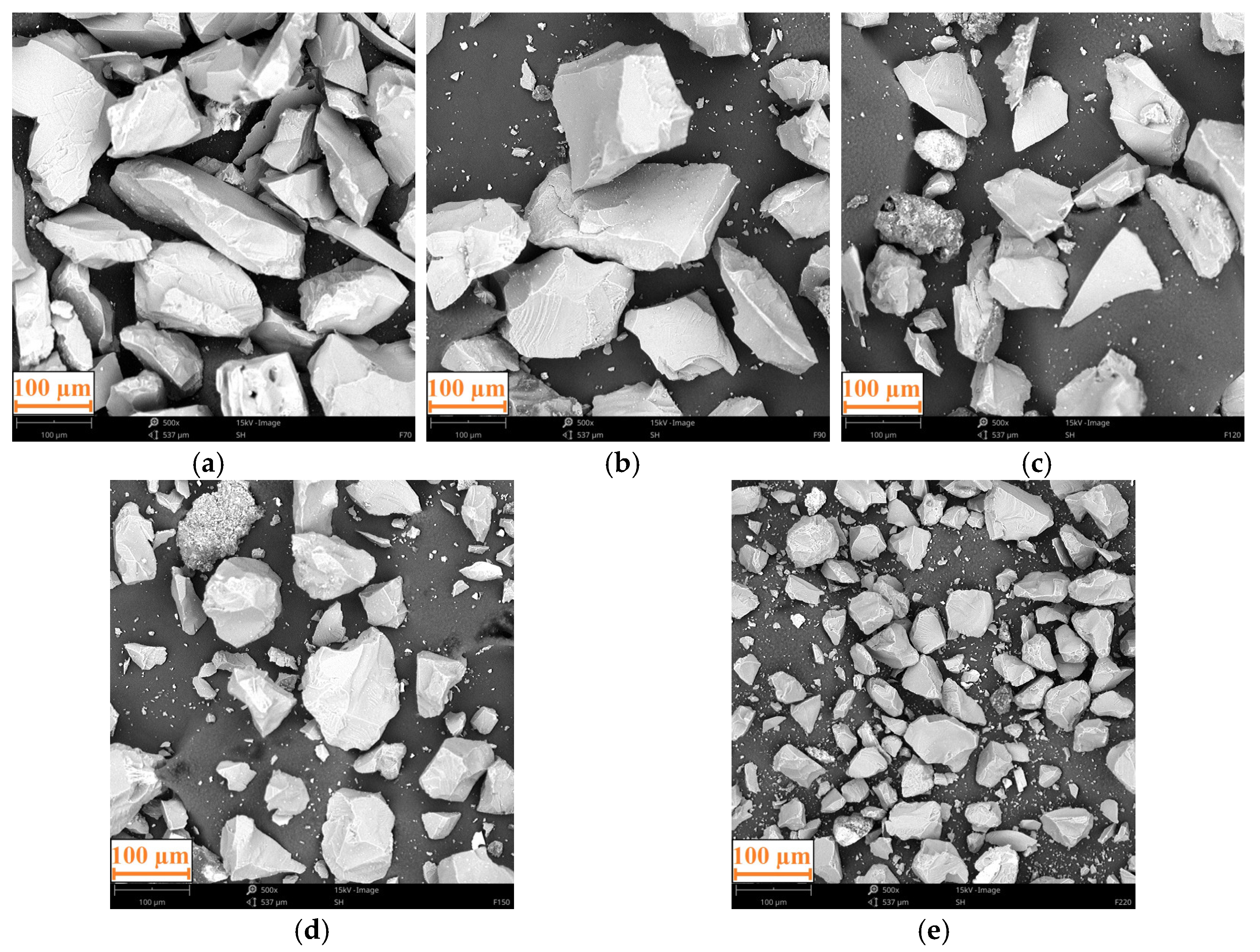
| Marking | Grain Size [µm] | |
|---|---|---|
| From | To | |
| F70 | 212 | 250 |
| F90 | 150 | 180 |
| F120 | 106 | 125 |
| F150 | 75 | 106 |
| F220 | 53 | 75 |
| Incidence Angle | Erosive Wear [μm] | ||||||||||||||
|---|---|---|---|---|---|---|---|---|---|---|---|---|---|---|---|
| F70 | F90 | F120 | F150 | F220 | |||||||||||
| σ | c | σ | c | σ | c | σ | c | σ | c | ||||||
| 45° | 129 | 11 | 14 | 128 | 7 | 9 | 152 | 9 | 12 | 134 | 15 | 19 | 112 | 20 | 24 |
| 60° | 45 | 4 | 6 | 63 | 8 | 10 | 62 | 13 | 16 | 53 | 11 | 14 | 30 | 3 | 4 |
| 90° | 22 | 15 | 12 | 15 | 5 | 6 | 27 | 11 | 13 | 16 | 6 | 7 | 16 | 3 | 4 |
Disclaimer/Publisher’s Note: The statements, opinions and data contained in all publications are solely those of the individual author(s) and contributor(s) and not of MDPI and/or the editor(s). MDPI and/or the editor(s) disclaim responsibility for any injury to people or property resulting from any ideas, methods, instructions or products referred to in the content. |
© 2025 by the authors. Licensee MDPI, Basel, Switzerland. This article is an open access article distributed under the terms and conditions of the Creative Commons Attribution (CC BY) license (https://creativecommons.org/licenses/by/4.0/).
Share and Cite
Sokolska, J.; Sokolski, P. Effect of Grain Size and Incidence Angle on Erosive Wear of Polyurea Coating. Appl. Sci. 2025, 15, 7568. https://doi.org/10.3390/app15137568
Sokolska J, Sokolski P. Effect of Grain Size and Incidence Angle on Erosive Wear of Polyurea Coating. Applied Sciences. 2025; 15(13):7568. https://doi.org/10.3390/app15137568
Chicago/Turabian StyleSokolska, Justyna, and Piotr Sokolski. 2025. "Effect of Grain Size and Incidence Angle on Erosive Wear of Polyurea Coating" Applied Sciences 15, no. 13: 7568. https://doi.org/10.3390/app15137568
APA StyleSokolska, J., & Sokolski, P. (2025). Effect of Grain Size and Incidence Angle on Erosive Wear of Polyurea Coating. Applied Sciences, 15(13), 7568. https://doi.org/10.3390/app15137568