Abstract
Web-tapered beams with I-sections, which are aesthetic and structurally efficient, have been widely used in steel structures. Web-tapered I-section beams bent about the strong axis may undergo out-of-plane buckling through lateral deflection and twisting. This primary stability failure mode in slender beams is known as lateral-torsional buckling (LTB). Unlike prismatic I-beams, the complex mode shape of web-tapered I-section beams makes it challenging or even impossible to derive a closed-form expression for the LTB load under certain transverse loading conditions. Therefore, the LTB assessment of web-tapered I-section beams is primarily performed using finite element analysis (FEA). However, this method involves multiple steps, requires specialized expertise, and demands significant computational resources, making it impractical in certain cases. This study proposes an analytical approach based on the Ritz method to evaluate the LTB of simply supported web-tapered beams with doubly or mono-symmetric I-sections. The proposed analytical method accounts for web tapering, I-section mono-symmetry, types and positions of transverse loads, and beam slenderness. The method was implemented in Mathematica to allow the rapid evaluation of the LTB capacity of web-tapered I-beams. The study validates the LTB loads computed using the developed Mathematica package against results from shell-based FEA. An excellent agreement was observed between the analytically and numerically calculated LTB loads.
1. Introduction
Beams with I-sections are commonly used in steel structures. They bear bending effects on their major axis with greater flexural rigidity, allowing for the economical use of material. Simply supported web-tapered beams with I-sections have also been preferred in structural practice due to their aesthetic features and lightweight nature. They are structurally efficient, as the optimum design can be achieved by varying their web dimensions in consideration of the moment distribution along the beam. The fact that the web height is highest at the mid-span of the beam, where the bending moment is highest, and the web height gradually decreases towards the supports, makes simply supported web-tapered beams with I-sections structurally efficient. However, lateral-torsional buckling (LTB) is the main failure mode for prismatic and web-tapered I-section beams. In this failure mode, a simply supported web-tapered I-section beam bent about its strong axis may buckle out of plane through lateral deflection and twisting once the applied transverse loads reach a critical level. During LTB, the compression flange tends to buckle laterally, while the remaining cross-section resists this lateral bending. As a result, the cross-section undergoes both twisting and lateral deflection. From a design perspective, LTB may occur well before the outer fibers of the cross-section reach their yield strength. Therefore, determining the elastic LTB load during the design stage is essential. The fundamental concepts of the LTB and classical differential equation solutions for beams, columns, beam-columns, and cantilevers under basic loading conditions are well-documented in the literature [1,2,3,4,5,6,7,8,9,10]. The Ritz and Galerkin methods are energy-based techniques commonly used to analyze LTB behavior. The Ritz method works directly with the total potential energy, converting it from a functional to a function using an assumed deflected shape that satisfies the structure’s kinematic boundary conditions. This transformation allows the use of standard calculus instead of the more complex variational calculus required for minimizing energy. This process enables the determination of the elastic critical LTB load. On the other hand, the Galerkin method originates from energy principles but employs the differential equilibrium equation during the solution process. Using a displacement function that satisfies kinematic and natural boundary conditions, the elastic critical LTB load is obtained via the Galerkin integral. These two energy approaches have been utilized to treat the LTB of beams, beam-columns subjected to combined axial and transverse load, castellated beams [11,12,13,14,15,16,17,18,19,20,21,22,23], beams with various cross-sections [24,25,26], and cantilevers [27,28,29,30,31,32,33].
A limited number of studies are related to the LTB of tapered beams, beam-columns, and cantilevers. Kitipornchai and Trahair [34,35] studied the LTB of web- or flange-tapered beams with I-sections. Trahair [36] proposed a finite element formulation to analyze the LTB response of tapered beam-columns under varying load cases and support configurations. A simplified formulation for the LTB resistance of web-tapered beams with symmetric I-profiles subjected to uniformly distributed loads was presented by Benyamina et al. [37]. The power series approach was employed by Asgarian et al. [38] to study the LTB response of tapered beams with general cross-sections and support configurations. The study considered the effects of the initial stresses and load eccentricities. Additionally, several numerical examples validated by the FEA were presented. Kuś [39] examined the lateral-torsional buckling response of beams with simultaneous tapering in both the flanges and the web. Osmani and Meftah [40] investigated the LTB response of web-tapered I-section beam-columns subjected to combined axial and transverse loads, incorporating shear deformation effects into their analysis. Andrade and Camotim [41] presented a general variational formulation to analyze the LTB behavior of singly symmetric thin-walled tapered beams. The study extended kinematical assumptions developed for the LTB of prismatic beams, derived the total potential of the tapered beam, and employed Trefftz’s criterion for stability analysis. The study included numerical examples to unveil the LTB behavior of tapered beams and cantilevers. The study concluded that tapered beams may exhibit higher or lower critical moments than their prismatic counterparts depending on the tapering ratio and loading conditions. Another important outcome was that tapering reduces the distance between the load application point and the torsional center for cantilevers, increasing stability despite the material reduction. Andrade et al. [42] evaluated the validity and underlying assumptions of a one-dimensional (1D) analytical model designed to investigate the LTB behavior of singly symmetric, web-tapered, thin-walled I-beams. The 1D model, which incorporated the effects of pre-buckling deflections, was benchmarked against results obtained from two-dimensional shell finite element analyses (FEA) performed using the ABAQUS software. The primary objective was to assess the accuracy of the 1D model’s predictions regarding critical loads and associated buckling modes across various geometric configurations and loading conditions. The study revealed that the 1D model provided accurate predictions for the critical LTB loads and buckling modes for longer beams. However, significant discrepancies were observed for shorter beams due to local effects, such as web or flange distortion, which the 1D model was unable to capture. The study also concluded that pre-buckling deflections influenced LTB loads, especially in web-tapered cantilevers subjected to transverse loads at the centroid or bottom flange. Zhang and Tong [43] introduced a variational principle for the LTB analysis of web-tapered beams with symmetric I-sections, which derives the total potential energy by considering all relevant longitudinal, shear, and transverse stresses. The proposed theory encompasses the effects of tapering, nonlinearities, and detailed deformation mechanics, providing a comprehensive and realistic approach for analyzing the LTB of web-tapered I-beams. Yilmaz [44] introduced an analytical method to assess the LTB load of flanges and/or web-tapered I-section cantilevers, developed a Mathematica package, and validated analytical solutions using FEA, where shell elements were employed. Yuan et al. [45] examined the LTB of web-tapered T-section cantilevers. The study highlighted that these cantilevers exhibit remarkable differences from those with I-sections. They expressed that the lack of the bottom flange compressed the lower part of the web, increasing buckling instability. Additionally, the study revealed that web tapering can increase or decrease critical lateral-torsional buckling loads depending on the flange width of the beam.
Numerous studies have demonstrated that the lateral-torsional buckling (LTB) behavior of web-tapered beams is qualitatively distinct from that of prismatic members. Simplified modeling approaches that represent tapered beams as equivalent or piecewise prismatic segments have been shown to yield unreliable or inaccurate buckling predictions, as they fail to account for critical geometric variations and deformation modes inherent to tapered geometries [41,42,43]. The application of energy methods enables the establishment of closed-form equations for the LTB of simply supported prismatic I-section beams and parametric equations for prismatic cantilevers with I-sections. However, since the buckling mode shapes of the web-tapered I-beams and tapered cantilevers with I sections are more complex, forming a closed-form simplified equation may be impossible for transverse load types varying moment distribution along the beam, considering their position on the cross-section. No study has provided simplified equations to determine the LTB load of web-tapered mono-symmetric I-beams under various transverse loads and load positions. The LTB assessment of web-tapered I-beams is typically conducted using finite element analysis (FEA) with solid and shell elements. However, FEA involves numerous steps requiring specialized expertise and substantial computational resources. Therefore, using FEA for the rapid evaluation of LTB for web-tapered I-beams may be impractical. This study first developed an analytical treatment based on the Ritz method to compute the LTB load of simply supported web-tapered beams with doubly symmetric and mono-symmetric I-sections. The analytical model accounts for web tapering, I-section monosymmetry, transverse load types, load height level, and slenderness effects. The model has been implemented in Mathematica v11.0 software [46]. Therefore, the LTB load of web-tapered I-section beams can be instantly calculated using the Mathematica package by simply defining the geometric dimensions and material properties (elastic modulus and Poisson’s ratio). The LTB loads calculated by the developed Mathematica package have been validated against shell-based FEA results obtained using ABAQUS/CAE v2021 software [47].
2. Analytical Model and the Development of the Mathematica Package
In the initial stage of LTB, the simply supported web-tapered I-section beam bends about its major axis. When the transverse loads reach a critical value, the web-tapered beam with an I-section buckles out of the plane, deflecting laterally and twisting. Figure 1a depicts the LTB of a simply supported web-tapered beam with a mono-symmetric I-section under a concentrated load at the mid-span of the beam. The tapering angle and the beam’s length are shown as α and L in Figure 1a,b, which show an m-m section of the web-tapering beam with the I-section. In Figure 1b, S and C represent the shear center and the centroid, respectively. The corresponding displacements of the shear center are expressed as u for lateral, v for vertical, and φ for torsional rotation. Besides, the y0 refers to the distance between the shear center and the center of gravity. The cross-section dimensions of the mono-symmetric I-section belonging to the web-tapered beam are shown in Figure 2. While bf1 and bf2 are the top and bottom flange widths, the top and bottom flanges’ thicknesses are demonstrated with tf1 and tf2, respectively. The parameters d and h indicate the overall height of the cross-section and the web depth, respectively. The h parameter varies with the distance measured from the left support in the z-axis due to the web tapering and can be written as follows:
where hi and hm are the web height at the left support and mid-span of the beam, respectively. The cross-section height d and its values at left support di and mid-span dm can be defined as follows:
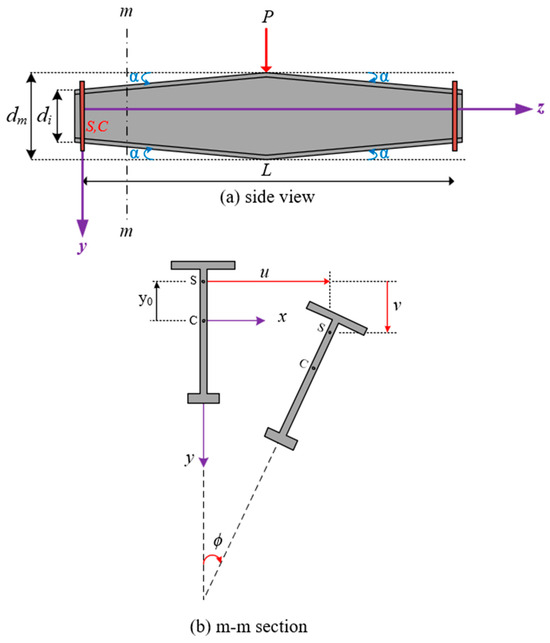
Figure 1.
The LTB of the tapered beam with mono-symmetric I-section (a) side view, (b) m-m section.
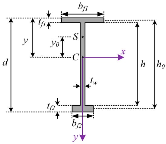
Figure 2.
The geometric dimensions of the cross-section of the tapered beam.
In Figure 2, y(z) represents the vertical distance from the centroid of the cross-section to its top edge and is expressed as follows:
The terms Af1(z), Af2(z), and Aw(z) denote the cross-sectional areas of the top and bottom flanges and the web, respectively. A(z) represents the total cross-sectional area. In the case of the mono-symmetric I-section shown in Figure 1a, the warping constant Cw(z), torsional constant J(z), and the minor-axis moment of inertia Iy(z) are key sectional properties influencing the LTB. Their expressions are given as follows:
where denotes the vertical distance from the centroid of the cross-section to the centerline of the top flange, while h0(z) represents the distance between the centroids of the flanges. The , h0(z), and y0(z) can be given in Equations (7)–(10).
The strain energy stored in a web-tapered beam with an I-section due to lateral bending, warping, and torsion, respectively, can be written as follows [43]:
where E and G denote the Young’s modulus and the shear modulus, respectively. The external work associated with transverse loading is formulated in Equation (12) [32,44]:
The function of the bending moment distribution along the beam’s length is defined as Mx(z). Out-of-shear center loading of concentrated load P causes extra torque of PHpΦp because the concentrated load moves due to the cross-section rotation during LTB. When the application point of P is below the shear center, the extra torque that occurs opposes the twist rotation of Φp and increases the LTB load. However, the LTB load decreases when the application point of P is above the shear center since, in that case, extra torque tends to enhance twist rotations. Therefore, extra work due to the out-of-shear center loading of P can be written as the second term of Equation (12). Similarly, the extra work done by the out-of-shear center loading of the distributed load q can be defined as the last term of Equation (12). The distances between the shear center and the application points of the concentrated force P and distributed load q, denoted by Hp and Hq, are taken as positive when the transverse loads act below the shear center. The variable Φp represents the twist angle at the location where the point load is applied. The LTB behavior of monosymmetric I-sections is more complex than that of symmetric I-sections. Different from the symmetric I-sections, an additional torque develops as a result of the section’s monosymmetric geometry, induced by the interaction between longitudinal bending stresses and twisting during the buckling process. This extra torque substantially influences the torsional stiffness of the beam. Torsional stiffness should be modified considering the major axis bending moment and the beam’s monosymmetry parameter for accurate LTB assessment [29]. The coefficient βx, introduced by Wagner, quantifies the cross-sectional monosymmetry and is formulated in Equation (13) [32]. In Equation (13), x and y represent the Cartesian coordinates corresponding to the differential area element (dA). Ix represents the major axis moment of inertia and is expressed for web-tapered mono-symmetric I-section beams as a function of the z-axis in Equation (14). y0 is taken as positive when the shear center lies below the centroid of the cross-section.
Based on Vlassov’s assumptions, the total potential energy (Π = U + V) for mono-symmetric tapered I-beams is expressed in Equation (16). The model treats the cross-section as in-plane rigid and excludes shear effects on its median surface [32,44].
The Ritz method relies on the principle that the extra strain energy accumulated during lateral-torsional buckling equals the additional work done by the applied loads. This energy-based approach necessitates an assumed buckled shape that satisfies the kinematic boundary conditions and closely resembles the beam’s actual deformed configuration. Consequently, the LTB load is then obtained by substituting the predefined buckling shape into the total potential energy expression. Kinematic boundary conditions, which impose geometric restrictions on displacements and rotations at support points, play a crucial role in defining the admissible shape function. For a simply supported beam, the restraint conditions at the supports (z = 0 and z = L) are u = Φ = 0 and d2u/dz2 = d2Φ/dz2 = 0. The buckled shape of a web-tapered mono-symmetric I-section beam is described by the lateral displacement of the shear center (u) and the twist angle of the cross-section (Φ). Taking into account the corresponding boundary conditions, the buckled shape functions are constructed as shown in Equation (17), where Ai and Bi represent the amplitudes of the mode shape functions.
By substituting the buckled shape functions defined in Equation (17) into the total potential energy expression in Equation (16), one obtains:
In Equation (18), f is a function with 2n variables, namely the coefficients Ai and Bi. At the onset of lateral-torsional buckling, the total potential energy reaches a stationary value, leading to the following necessary conditions:
These conditions yield a set of 2n homogeneous linear equations, which can be conveniently expressed in matrix notation:
where K is the stiffness-like coefficient matrix, and {d} = {A1, A2, A3, …,An, B1, B2, B3, …,Bn}T contains the unknown amplitudes. A non-trivial solution to Equation (20) exists only when the determinant of K vanishes:
Solving Equation (21) leads to a polynomial equation of degree 2n, whose smallest positive root corresponds to the critical elastic lateral-torsional buckling load or moment. Although this analytical procedure could not establish a closed-form simplified equation, it can be easily programmed by any mathematical software. Therefore, it can be used to calculate the elastic LTB loads of the web-tapered beams with doubly symmetric and mono-symmetric I-sections subjected to various transverse loads, considering their positions along the cross-section. The equations that formed the present analytical model were defined in the Mathematica software v11.0. In the proposed analytical procedure, integration was performed using a custom implementation of Simpson’s numerical method rather than relying on the software’s built-in symbolic integration capabilities. In the present analytical approach, all derivative operations were carried out using the software’s built-in symbolic differentiation algorithm. The Mathematica package includes twelve input parameters; the first eight are related to geometric dimensions, and the next two are for the definition of elastic material, so they are elastic modulus E and Poisson’s ratio ν. The last two inputs correspond to the transverse load type and its position. It should be noted here that shear modulus is determined from the formula of G = E/2(1 + ν). Equation (22) shows the input parameters of the Mathematica package:
Six common transverse load types, as shown in Figure 3, have been defined in the Mathematica package. The “loadType” input accepts an array of transverse loads, ranging from 1 to 6. For example, when 1 is entered as the input for “loadType”, the LTB load is calculated for a concentrated load at mid-span. Users can practically add new transverse load types to the Mathematica package, considering the moment distribution function along the beam existing in the Mx(z) term. The “loadPosition” input allows for the definition of the transverse loads’ position along the cross-section. Three loading positions have been considered in the Mathematica package. The variable “loadPosition” is assigned values of −1, 0, or 1 to indicate loading applied at the top flange, shear center, and bottom flange, respectively. The only output of the present Mathematica package is the elastic LTB load of a web-tapered beam with an I-section. However, users can add more outputs using basic Mathematica commands. For instance, the variation of the mono-symmetry parameter βx along the beam can be included in the outputs. Eventually, the present Mathematica package, called LTBWTB, can calculate the elastic LTB load of a web-tapered beam with an I-section, requiring only geometric dimensions, the elastic modulus, and Poisson’s ratio, under the effect of six load types and three load height levels along the cross-section. The LTBWTB tool provides structural designers with a rapid means of evaluating the lateral-torsional buckling (LTB) load of web-tapered I-section beams, offering a practical alternative to shell-based finite element analysis (FEA). Unlike FEA, which involves multiple stages such as 3D geometry creation, section assignment, meshing, load and boundary condition definition, and result interpretation, LTBWTB simplifies the process and eliminates the need for specialized expertise. For some examples, the inputs and outputs of LTBWTB are presented in Figure 4. Additionally, Figure 5 illustrates the software’s flowchart.
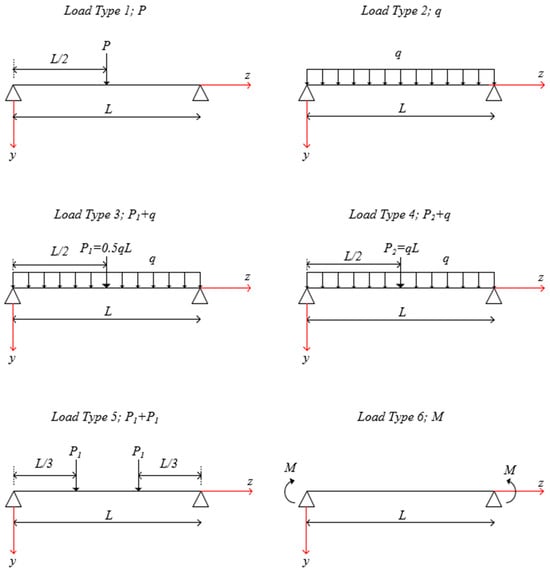
Figure 3.
The considered load cases in the numerical analysis.
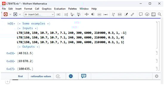
Figure 4.
The inputs and outputs of the LTBWTB software.
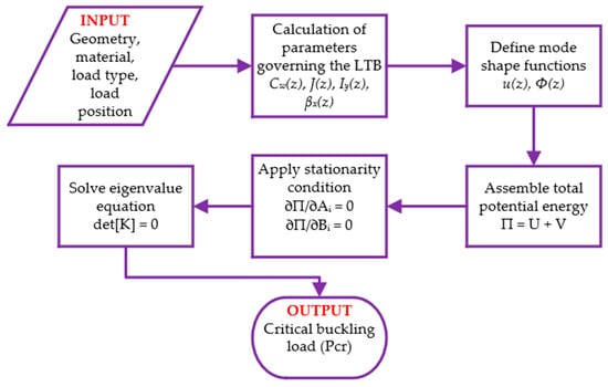
Figure 5.
The flow chart of the LTBWTB software.
3. Numerical Analysis
In numerical analysis, four different simply supported web-tapered beams with I-sections were designed to validate the LTB loads obtained from LTBWTB. Two had doubly symmetric I-sections, and the other had mono-symmetric I-sections. The lengths of the beams were 6.0 m and 8.0 m, resulting in beams with different slenderness ratios. The geometric dimensions of the four simply supported web-tapered beams with I-sections are presented in Table 1. In the numerical examples, the elastic modulus was assumed to be 210,000 MPa. Poisson’s ratio was 0.3. The LTB loads for all beams were computed under six different transverse load types, which are applied to the top and bottom flanges and the shear center.

Table 1.
The geometric dimensions of web-tapered I-beams.
Shell-based finite element analysis (FEA) using the S8R5 element, which accounts for warping effects, was performed in ABAQUS/CAE (version 2021) software to assess the LTB of simply supported web-tapered beams with I-sections. The S8R5 shell element is an 8-node doubly curved thin shell with reduced integration using five degrees of freedom per node. Element type S8R5 has three displacements and two rotation variables at an internally generated midbody node [48]. Several studies have demonstrated that the S8R5 shell element yields accurate results for LTB evaluation [11,13,14,22,30,32,44]. The formulation of such reduced-integration quadrilateral shell elements and their capability to capture instability phenomena, including local-global mode interaction, is extensively detailed in the study of Belytschko et al. [49]. The beams were discretized into 60, 8, and 4 mesh elements along the length, web, and flange, respectively. Additionally, further mesh refinement did not significantly affect LTB loads, although it increased computation time. While eight and four meshes along the web and flange were kept constant, the mesh through the beam’s length was changed for the WTB1, subjected to a point load on its top flange, for the mesh convergence study. The mesh convergence results are summarized in Table 2.
Table 2.
The results of the mesh convergence study.
For instance, the finite element model of the web-tapered beam 2 (WTB2) is presented in Figure 6. In the modeling phase, first, the 2D geometry of the tapered web was generated. Flange widths were arranged with the Shell Extrude command by selecting the top and bottom lines of the web in two directions. After the Shell Extrude operation, the model consisted of three shell parts. This process allowed for three sections to be connected from their intersections without any extra constraint properties, such as tie contact. Homogeneous shell sections were modeled for flanges and web by defining elastic material properties and shell thickness. Shell sections generated were assigned to the flanges and the web. The Assign Element Type Command was used for assigning the S8R5 mesh element to flanges and the web. With the Seed Edges command, the flanges and web were divided into finite elements. Using the Create Mesh Part command, an independent part was created based on the meshed geometry. The original CAD geometry was discarded, and further geometric operations such as partitioning, sketching, and extrusion could not be performed. However, nodes, shell elements, and sets remained in the new part. The new part was imported into the Assembly module. The Linear Perturbation procedure and Buckle were chosen from the Step menu for lateral-torsional buckling analysis. Loads were applied to the nodes. Boundary conditions were applied to nodes located in the two end cross-sections. Vertical and lateral translations that were perpendicular to the beam’s longitudinal axis were restrained. Finally, the analysis was executed, and the buckling load results were visualized.
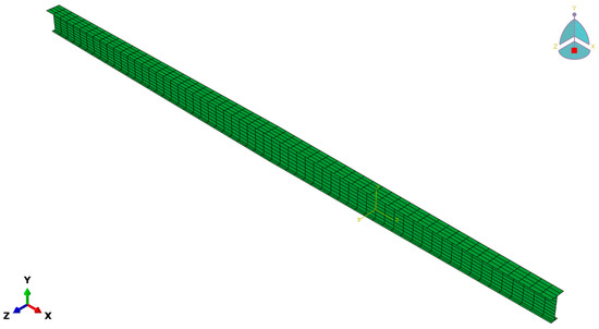
Figure 6.
The shell finite element model of web-tapered beam 2 (WTB2).
Table 3, Table 4, Table 5 and Table 6 show the elastic LTB loads of web-tapered I-section beams subjected to six different types of loads and three load height levels, including the top (TF) and bottom flanges (BF) and shear center (SC) loadings, calculated using LTBWTB and FEA. The R in Table 3, Table 4, Table 5 and Table 6 refers to the ratio of LTBWTB to FEA. Figure 7 illustrates the LTB shapes of web-tapered beams with I-sections under the point load at their mid-span.
Table 3.
The LTB loads of WTB1 obtained by LTBWTB and FEA.
Table 4.
The LTB loads of WTB2 obtained by LTBWTB and FEA.
Table 5.
The LTB loads of WTB3 obtained by LTBWTB and FEA.
Table 6.
The LTB loads of WTB4 obtained by LTBWTB and FEA.
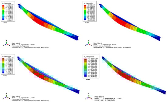
Figure 7.
The buckled shape of web-tapered I-beams under concentrated load (Units are in N).
An examination of Table 3, Table 4, Table 5 and Table 6 shows that the maximum difference between the LTBWTB and shell-based FEA results reached 5%, with an average difference of only 1%. It is considered that there is a strong correlation between analytical and numerical results for LTB problems [13,14,32,38,42,44]. The comparative LTB loads presented in Table 3, Table 4, Table 5 and Table 6 indicate that LTBWTB can calculate the elastic LTB loads of web-tapered beams with both doubly symmetric and monosymmetric I-sections entirely in accord with the FEA across all six transverse load types and three load height levels (TF, SC, BF). Additionally, it can be concluded that LTBWTB can capture the slenderness effect, as the LTB loads of WTB3 and WTB4, which were relatively more slender than WTB1 and WTB2, respectively, also aligned with those obtained by FEA. The average and maximum differences between the LTB loads calculated by LTBWTB and FEA for WTB1 and WTB2 were 1% and 3%, respectively. These differences were 1% and 2% for the more slender beams, WTB3 and WTB4, respectively. Despite there being negligible differences between the elastic LTB loads obtained from LTBWTB and FEA, the LTB loads determined with LTBWTB, based on the 1D frame element formulation using the Ritz method, show greater agreement with shell-based FEA as slenderness increased, and the differences tended to diminish. This tendency occurred because the one-dimensional frame element assumption became more valid as the beams’ length increased, thereby increasing slenderness. In the analysis of LTB behavior for relatively short beams, the one-dimensional frame element model underlying LTBWTB may not adequately capture localized web buckling or significant web/flange distortions near the load application region, which are more accurately represented in the FEA [30,32,42,44]. For further discussion on the interaction between local plate instability and global buckling, refer to the classical works of Tvergaard and Needleman [50,51], which are available for consultation.
Table 7 presents a comparison of the LTB loads of web-tapered beams subjected to distributed load on their shear center, which was obtained from LTBWTB and Asgarian et al. [38]. The present analytical model is based on the Ritz method, while Asgarian et al. [38] have utilized Galerkin’s method. The maximum and average discrepancies between the LTB loads obtained by these two energy-based methods were 2% and 1.5%, respectively. This is another demonstration that LTBWTB accurately predicted the LTB loads of web-tapered beams with I-section.
Table 7.
The LTB loads of tapered beams subjected to q loads on their shear center obtained from LTBWTB and Asgarian et al. [38].
Consequently, the proposed analytical method, along with the developed Mathematica-based software package LTBWTB, can accurately predict the lateral-torsional buckling (LTB) loads of web-tapered I-section beams. The results showed excellent agreement with shell-based finite element analysis (FEA), as the method effectively captured the influence of tapering, member slenderness, moment gradients induced by transverse loading, and the load height level along the cross-section.
4. Conclusions
Structural designers often resort to finite element analyses (FEA) to determine the lateral-torsional buckling (LTB) loads of web-tapered simply supported doubly symmetric and mono-symmetric I-section beams under various transverse loads, as there is no detailed and easily applicable analytical method or closed-form formula available in the literature. However, conducting an FEA requires specialized expertise due to the complexity of several steps, including geometry generation, material property definition, section assignment, finite element meshing, the application of loads and boundary conditions, analysis execution, and result interpretation. Moreover, the increased modeling and computation time poses a significant challenge for practical applications. This study proposes an analytical method based on an energy approach to compute the LTB load of web-tapered simply supported I-section beams. The analytical method accounts for the monosymmetry of the I-section, the moment distribution through the beam due to transverse loads, load height level along the cross-section, web tapering levels, and slenderness effects. The analytical method was programmed with Mathematica software, and a package named LTBWTB was developed. Through the LTBWTB, only the geometric dimensions of the web-tapered beam and elastic material properties are required to determine the LTB load under the given loading type and position. In comparison to shell-based FEA, LTBWTB offers a faster and more practical means of evaluating the LTB load of web-tapered simply supported I-section beams. A numerical study was conducted in which the LTB loads were computed using both LTBWTB and FEA. The maximum and average differences between the two methods were 5% and 1%, respectively. The results demonstrate that LTBWTB accurately accounts for I-section mono-symmetry, loading type, loading position, web tapering level, and slenderness in LTB load calculation. The strong agreement between the LTBWTB results and the shell-based FEA results confirms that the developed software can be reliably used for determining the LTB load of web-tapered I-section beams.
Supplementary Materials
The following supporting information can be downloaded at: https://www.mdpi.com/article/10.3390/app15137572/s1, File LTBWTB: A Mathematica Software to Evaluate the Lateral-Torsional Buckling Load of Web-Tapered Mono-Symmetric I-Section Beams.
Funding
This research received no external funding.
Institutional Review Board Statement
Not applicable.
Informed Consent Statement
Not applicable.
Data Availability Statement
The original data presented in the study are openly available in article/Supplementary Material. Further inquiries can be directed to the author.
Conflicts of Interest
The author declares no conflict of interest.
References
- Perelmuter, A.V.; Slivker, V.I. Handbook of Mechanical Stability in Engineering; World Scientific Publishing Co Pte Ltd.: Singapore, 2013. [Google Scholar] [CrossRef]
- Bazant, Z.P.; Cedolin, L. Stability of Structures: Elastic, Inelastic, Fracture and Damage Theories; World Scientific Publishing Co Pte Ltd.: Singapore, 2010. [Google Scholar] [CrossRef]
- Ziegler, H. Principles of Structural Stability; Blaisdell Publishing Company: Waltham, MA, USA, 1968. [Google Scholar]
- Timoshenko, S.P.; Gere, J.M. Theory of Elastic Stability, 2nd ed.; McGraw-Hill: New York, NY, USA, 1961. [Google Scholar]
- Chen, W.F.; Atsuta, T. Theory of Beam-Columns: Space Behavior and Design; McGraw-Hill: New York, NY, USA, 1977; Volume 2. [Google Scholar]
- Chen, W.F.; Lui, E.M. Structural Stability: Theory and Implementation; Elsevier Science Publishing Co. Inc.: New York, NY, USA, 1987. [Google Scholar]
- Galambos, T.V.; Surovek, A.E. Structural Stability of Steel: Concepts and Application for Structural Engineers; John Wiley and Sons: Hoboken, NJ, USA, 2008. [Google Scholar]
- Trahair, N.S. Flexural-Torsional Buckling of Structures; CRC Press: London, UK, 1993. [Google Scholar]
- Mohri, F.; Brouki, A.; Roth, J.C. Theoretical and Numerical Stability Analyses of Unrestrained, Mono-Symmetric Thin-Walled Beams. J. Constr. Steel Res. 2003, 59, 63–90. [Google Scholar] [CrossRef]
- Iandiorio, C.; Salvini, P. Large displacements of slender beams in plane: Analytical solution by means of a new hypergeometric function. Int. J. Solids Struct. 2020, 185–186, 467–484. [Google Scholar] [CrossRef]
- Mohri, F.; Bouzerira, C.; Potier-Ferry, M. Lateral buckling of thin-walled beam-column elements under combined axial and bending loads. Thin-Walled Struct. 2008, 46, 290–302. [Google Scholar] [CrossRef]
- Mohri, F.; Damil, N.; Potier-Ferry, M. Buckling and lateral buckling interaction in thin-walled beam-column elements with mono-symmetric cross sections. Appl. Math. Model. 2013, 37, 3526–3540. [Google Scholar] [CrossRef]
- Yilmaz, T.; Kirac, N. Analytical and parametric investigations on lateral torsional buckling of European IPE and IPN beams. Int. J. Steel Struct. 2017, 17, 695–709. [Google Scholar] [CrossRef]
- Yilmaz, T.; Kiraç, N.; Anil, Ö. An alternative evaluation of the LTB behavior of mono-symmetric beam-columns. Steel Compos. Struct. 2019, 30, 471–481. [Google Scholar] [CrossRef]
- Yilmaz, T.; Kirac, N.; Kilic, T. Lateral-Torsional Buckling of European Wide Flange I-Section Beams. In Proceedings of the 2nd World Congress on Civil, Structural and Environmental Engineering (CSEE’17), Barcelona, Spain, 2–4 April 2017. [Google Scholar]
- Kim, B.; Li, L.; Edmonds, A. Analytical Solutions of Lateral-Torsional Buckling of Castellated Beams. Int. J. Struct. Stab. Dyn. 2016, 16, 155044. [Google Scholar] [CrossRef]
- Torkamani, M.A.M.; Roberts, E.R. Energy Equations for Elastic Flexural-Torsional Buckling Analysis of Plane Structures. Thin-Walled Struct. 2009, 47, 463–473. [Google Scholar] [CrossRef]
- Ozbasaran, H. Convergence of the Rayleigh–Ritz Method for buckling analysis of arbitrarily configured I-section beam–columns. Arch. Appl. Mech. 2019, 89, 2397–2414. [Google Scholar] [CrossRef]
- Saoula, A.; Selim, M.M.; Meftah, S.A.; Benyamina, A.B.; Tounsi, A. Simplified analytical method for lateral torsional buckling assessment of RHS beams with web openings. Structures 2021, 34, 2848–2860. [Google Scholar] [CrossRef]
- Belaid, T.; Ammari, F.; Adman, R. Influence of load position on critical lateral torsional buckling moment of laterally restrained beam at tense flange. Asian J. Civ. Eng. 2018, 19, 839–848. [Google Scholar] [CrossRef]
- Bresser, D.; Ravenshorst, G.J.P.; Hoogenboom, P.C.J. General formulation of equivalent moment factor for elastic lateral torsional buckling of slender rectangular sections and I-sections. Eng. Struct. 2020, 207, 110230. [Google Scholar] [CrossRef]
- Aydin, R.; Gunaydin, A.; Kirac, N. On the Evaluation of Critical Lateral Buckling Loads of Prismatic Steel Beams. Steel Compos. Struct. 2015, 18, 603–621. [Google Scholar] [CrossRef]
- Mohammadi, E.; Hosseini, S.S.; Rohanimanesh, S.M. Elastic lateral-torsional buckling strength and torsional bracing stiffness requirement for monosymmetric I-beams. Thin-Walled Struct. 2016, 104, 116–125. [Google Scholar] [CrossRef]
- Cheng, S.; Kim, B.; Li, L. Lateral–torsional buckling of cold-formed channel sections subject to combined compression and bending. J. Constr. Steel Res. 2013, 80, 174–180. [Google Scholar] [CrossRef]
- Saoula, A.; Meftah, S.A.; Mohri, F.; Daya, E.M. Lateral buckling of box beam elements under combined axial and bending loads. J. Constr. Steel Res. 2016, 116, 141–155. [Google Scholar] [CrossRef]
- Zhang, L.; Tong, G. Lateral buckling of simply supported C- and Z-section purlins with top flange horizontally restrained. Thin-Walled Struct. 2016, 99, 155–167. [Google Scholar] [CrossRef]
- Andrade, A.; Camotim, D.; Providência e Costa, P. On the evaluation of elastic critical moments in doubly and singly symmetric I section cantilevers. J. Constr. Steel Res. 2007, 63, 894–908. [Google Scholar] [CrossRef]
- Zhang, L.; Tong, G. Elastic flexural-torsional buckling of thin-walled cantilevers. Thin-Walled Struct. 2008, 46, 27–37. [Google Scholar] [CrossRef]
- Wang, C.M.; Kitipornchai, S. On Stability of Monosymmetric Cantilevers. Eng. Struct. 1986, 8, 168–180. [Google Scholar] [CrossRef]
- Ozbasaran, H.; Aydın, R.; Dogan, M. An Alternative Design Procedure for Lateral-Torsional Buckling of Cantilever I-Beams. Thin-Walled Struct. 2015, 90, 235–242. [Google Scholar] [CrossRef]
- Aydin, R.; Ozbasaran, H.; Kirac, N.; Gunaydin, A. Lateral Torsional Buckling of Double Angle and Tee Cantilevers: A Parametric Study. In Proceedings of the Fourteenth International Conference on Civil, Structural and Environmental Engineering Computing, Sardinia, Italy, 3–6 September 2013; Civil-Comp Press: Stirlingshire, UK, 2013. [Google Scholar]
- Yilmaz, T. Rapid evaluation of lateral-torsional buckling of European standard I-section cantilevers. Mech. Based Des. Struct. Mach. 2024, 52, 4241–4259. [Google Scholar] [CrossRef]
- Zhang, W.F.; Liu, Y.C.; Hou, G.L.; Chen, K.S.; Ji, J.; Deng, Y.; Deng, S.L. Lateral-torsional buckling analysis of cantilever beam with tip lateral elastic brace under uniform and concentrated load. Int. J. Steel Struct. 2016, 16, 1161–1173. [Google Scholar] [CrossRef]
- Kitipornchai, S.; Trahair, N.S. Elastic stability of tapered I-beams. J. Struct. Div. ASCE 1972, 98, 713–728. [Google Scholar] [CrossRef]
- Kitipornchai, S.; Trahair, N.S. Elastic behaviour of tapered mono-symmetric I beams. J. Struct. Div. ASCE 1975, 101, 1661–1678. [Google Scholar] [CrossRef]
- Trahair, N. Lateral buckling of tapered members. Eng. Struct. 2017, 151, 518–526. [Google Scholar] [CrossRef]
- Benyamina, A.B.; Meftah, S.A.; Mohri, F.; Daya, E.M. Analytical solutions attempt for lateral torsional buckling of doubly symmetric web-tapered I-beams. Thin-Walled Struct. 2013, 56, 1207–1219. [Google Scholar] [CrossRef]
- Asgarian, B.; Soltani, M.; Mohri, F. Lateral-torsional buckling of tapered thin-walled beams with arbitrary cross-sections. Thin-Walled Struct. 2013, 62, 96–108. [Google Scholar] [CrossRef]
- Kus, J. Lateral-torsional buckling steel beams with simultaneously tapered flanges and web. Steel Compos. Struct. 2015, 19, 897–916. [Google Scholar] [CrossRef]
- Osmani, A.; Meftah, S.A. Lateral buckling of tapered thin-walled bi-symmetric beams under combined axial and bending loads with shear deformations allowed. Eng. Struct. 2018, 165, 76–87. [Google Scholar] [CrossRef]
- Andrade, A.; Camotim, D. Lateral–Torsional Buckling of Singly Symmetric Tapered Beams: Theory and Applications. J. Eng. Mech. 2005, 131, 586–597. [Google Scholar] [CrossRef]
- Andrade, A.; Camotim, D.; Dinis, P.B. Lateral-torsional buckling of singly symmetric web-tapered thin-walled I-beams: 1D model vs. shell FEA. Comput. Struct. 2007, 85, 1343–1359. [Google Scholar] [CrossRef]
- Zhang, L.; Tong, G. Lateral buckling of web-tapered I-beams: A new theory. J. Constr. Steel Res. 2008, 64, 1379–1393. [Google Scholar] [CrossRef]
- Yilmaz, T. A mathematica code for evaluating lateral torsional buckling of tapered cantilevers. E3S Web Conf. 2024, 579, 01002. [Google Scholar] [CrossRef]
- Yuan, W.; Kim, B.; Chen, C. Lateral-torsional buckling of steel web tapered tee-section cantilevers. J. Constr. Steel Res. 2013, 87, 31–37. [Google Scholar] [CrossRef]
- Wolfram Mathematica, v11.0. License Belongs to Eskisehir Osmangazi University, Turkey. Wolfram Research Inc.: Champaign, IL, USA, 2016.
- ABAQUS/CAE 2021; License Belongs to Konya Technical University, Turkey; Dassault Systèmes: Vélizy-Villacoublay, France, 2021.
- ABAQUS/CAE 2016; Analysis User’s Guide; Dassault Systèmes: Vélizy-Villacoublay, France, 2016.
- Belytschko, T.; Liu, W.K.; Moran, B.; Elkhodary, K. Nonlinear Finite Elements for Continua and Structures; John Wiley & Sons, Inc: Hoboken, NJ, USA, 2014. [Google Scholar]
- Tvergaard, V.; Needleman, A. Mode Interaction in an Eccentrically Stiffened Elastic-Plastic Panel under Compression. In Buckling of Structures; International Union of Theoretical and Applied Mechanics; Budiansky, B., Ed.; Springer: Berlin/Heidelberg, Germany, 1976. [Google Scholar] [CrossRef]
- Tvergaard, V.; Needleman, A. On the localization of buckling patterns. J. Appl. Mech. 1980, 47, 613–619. [Google Scholar] [CrossRef]
Disclaimer/Publisher’s Note: The statements, opinions and data contained in all publications are solely those of the individual author(s) and contributor(s) and not of MDPI and/or the editor(s). MDPI and/or the editor(s) disclaim responsibility for any injury to people or property resulting from any ideas, methods, instructions or products referred to in the content. |
© 2025 by the author. Licensee MDPI, Basel, Switzerland. This article is an open access article distributed under the terms and conditions of the Creative Commons Attribution (CC BY) license (https://creativecommons.org/licenses/by/4.0/).