1. Introduction
Harvesting energy from environmental sources has become an increasingly prominent research area in recent years due to its vast potential for various applications. Providing power to wireless electronics and sensor systems with minimal energy demands—especially in places where battery replacement is impractical—has proven highly advantageous for automation and remote monitoring. Therefore, energy harvesters have been engineered to convert ambient energy into a usable electrical form, enabling small wireless systems to operate throughout their service life.
In recent developments, vibration-induced energy harvesting has emerged as a particularly attractive solution and has seen growing academic and engineering interest. Vibrational energy can be converted into electrical power through three main mechanisms: electrostatic, electromagnetic, and piezoelectric methods [
1]. Among these, the piezoelectric approach stands out due to its compact size, versatility in shape design, and high energy conversion efficiency [
2]. Even minor mechanical vibrations can yield a notable electrical output, eliminating the need for low-efficiency mechanical triggering systems [
3]. The key functionality of piezoelectric materials lies in their ability to produce electrical charge in response to mechanical forces (direct effect) and to undergo mechanical deformation when subjected to an external electric field (inverse effect). The direct piezoelectric effect is particularly beneficial for converting mechanical vibrations into electrical energy to support intelligent and autonomous systems.
The literature contains numerous reviews that explore different piezoelectric energy harvester concepts and design strategies [
4,
5,
6,
7]. One of the most commonly studied designs is the cantilever beam with surface-attached piezoelectric elements, which operates under transverse vibrations. This design is valued for its structural simplicity and cost-effectiveness. These systems often exploit resonance to maximize strain in the piezoelectric material, which in turn, enhances electrical output. Furthermore, optimizing the physical shape of the harvester is considered a key area for performance enhancement.
For example, optimal cantilevers width designs were explored by Park et al. [
8], who conducted a parametric FEM-based study where the beam’s tip width and position of the piezoelectric patch were optimized under harmonic excitation. Their results showed a 37% increase in power output compared to a baseline rectangular configuration. The study highlighted that performance gains can be achieved without changing the material or beam length, simply by adjusting the geometric distribution of strain. Their work also emphasized the synergy between geometric shaping and dynamic tuning, showing that optimal patch placement both maximizes strain and avoids nodal points of the mode shape. However, the excitation was performed continuously to the tip of the cantilever and the eigen frequencies did not remain the same. Ben Ayed et al. [
9] proposed a quadratic width profile for piezoelectric unimorphs and compared their performance against rectangular and triangular counterparts. FEM simulations demonstrated significant improvements in strain uniformity and output power. Their optimization was particularly notable for maintaining constant volume, which allowed a fair comparison across geometries. The study demonstrated that quadratic profiles provided better energy conversion under real-world excitation levels by reducing stress concentration while distributing deformation more evenly across the piezoelectric surface. Karadag et al. [
10] extended this idea by introducing curved profiles into cantilever beams. Their experimental and numerical results indicated that, under a 5 g tip mass, a curved profile improved strain uniformity by 29% compared to triangular designs, which are already superior to rectangular ones. They validated the numerical optimization results with experimental prototypes fabricated via laser cutting and piezoelectric lamination, showing a close match between predicted and measured outputs. This study provides a rare full-cycle validation of optimization theory, simulation, and practical deployment.
In more advanced geometrical work, Goldschmidtboeing and Woias [
11] presented a comparative study of multiple beam shapes, including exponential, trapezoidal, and sinusoidal tapers. Their results showed that even minor profile changes can result in significant shifts in resonant frequency and strain energy distribution. This kind of shape-function tuning is critical in applications where ambient vibration characteristics are narrowband and require precise alignment with harvester dynamics. Nanthakumar et al. [
12] used topology optimization approaches to nanoscale piezoelectric structures, demonstrating how surface effects and scale-dependent material behavior significantly influence electromechanical coupling at micro- and nanoscales. Similarly, Wein et al. [
13] applied topology optimization with stress norm constraints to achieve uniform strain distribution in unimorph harvesters. Their method created hybrid geometries that offered superior performance in simulated environments, though they highlighted practical challenges related to stress concentrations at sharp corners and the fabrication of irregular contours.
Electrode layout and poling optimization have also been shown to significantly influence performance. Rather than relying on uniform polarization, Chen et al. [
14] introduced a method to spatially vary the electrical boundary conditions and polarization fields within the piezoelectric domain, allowing the device to more efficiently convert mechanical strain into electrical output. Their results showed that this tailored configuration leads to significantly better energy harvesting performance compared to conventional electrode arrangements. Stewart et al. [
15] and Erturk et al. [
16] analyzed the effect of modal strain nodes on electrode placement, showing that misalignment can cause charge cancellation and loss of output. Alternative poling strategies, such as d15-mode (shear mode) operation and interdigitated electrode configurations, were examined in [
17,
18]. These methods offer higher electromechanical coupling but often introduce additional complexity in fabrication and modeling. Zhao et al. [
17] showed that shear mode operation increased power by more than 60% under the same excitation conditions as conventional d31 mode designs.
Performance metrics reported in the literature vary but typically include tip deflection, average and peak strain, resonant frequency, voltage output, load-matched current, and power density. Yang et al. [
19] proposed arc-shaped piezoelectric elements, demonstrating experimentally that such curvature leads to a 200% increase in power density and 60% greater conversion efficiency compared to standard flat beams. In contrast, Wu et al. [
20] introduced a two-degree-of-freedom harvester capable of operating over a broader frequency range, with output improvements attributed to modal superposition and strain field enhancement. In the context of non-linear energy harvesting, Dai and Harne [
21] explored optimal charging conditions in bistable PEHs under harmonic excitation, offering insights into how system dynamics and electrical loading interact. Complementarily, Cai and Harne [
22] focused on the electrical side, optimizing power conditioning strategies for such systems and demonstrating how careful matching between mechanical response and load impedance maximizes harvested power. Yang et al. [
23] proposed a unified performance index termed “effectiveness”, which incorporates both mechanical quality factors and electrical transmission efficiency. This metric provides a comprehensive means of evaluating and comparing PEH designs beyond raw output values, capturing the dynamic interaction between structure and energy transduction.
To comprehensively address real-world operational factors in piezoelectric energy harvester design, the recent literature has emphasized the impact of external variables, such as mounting configuration, temperature fluctuations, and electrical matching strategies. In their article, Tang et al. [
24] explored how varying the installation angle of an airfoil-based harvester can significantly influence its aerodynamic flutter threshold and power output, demonstrating that moderate angles improve performance. Degefa et al. [
25] investigated the thermal sensitivity and frequency-dependent behavior of laminated macro-fiber composite harvesters, revealing the influence of environmental temperature on structural response and electrical generation. In line with electrical optimization, Quattrocchi et al. [
26] proposed a real-time impedance tracking approach using a Zeta converter and MPPT-based control system, achieving rapid power adaptation under dynamic environmental changes and ensuring efficient power transfer.
In the context of non-linear mechanisms, magnetic coupling has received growing interest for performance enhancement. Daukševičius et al. [
27] analyzed magnetic plucking dynamics in a frequency-upconverting harvester, uncovering key resonance conditions for energy amplification via repeated magnetic interactions. Rosso et al. [
28] further expanded this concept by experimentally examining the dynamical behavior of piezoelectric harvesters influenced by variable magnetic interaction speeds, confirming non-linear frequency up-conversion effects. Finally, Clementi et al. [
29] proposed a 2 + 1 degree-of-freedom equivalent circuit model for a LiNbO
3/metal/LiNbO
3 bimorph piezoelectric cantilever, enabling more accurate prediction of its electromechanical behavior and offering insights valuable for broadband vibration energy harvesting design.
Some designs do not necessarily come from math—it could be bioinspired. Such a structural design can significantly enhance the performance of vibration-based energy harvesters. Notably, Kim et al. examined a trunk-shaped piezoelectric cantilever beam inspired by the caudal peduncle of the electric fish
Gnathonemus petersii [
30]. The structure incorporates delta wing-shaped extensions that emulate the morphology of the fish’s tail, which is naturally evolved for efficient electrical signal generation. In their study, the biomimetic beam outperformed a conventional rectangular cantilever, yielding up to 45% more electrical output under vibrational excitation. This enhancement was attributed to improved strain distribution and potential non-linear amplification effects within the PVDF piezoelectric layer. The results suggest that evolutionary morphology, such as that found in electrogenic fish, may offer valuable templates for designing more efficient energy harvesting devices.
Despite the advancements in the mentioned literature, a notable limitation is the underexplored potential of optimizing non-linear thickness profiles for specific eigenfrequencies. While width variation and topology optimization are widely applied, thickness remains either constant or adjusted without explicitly considering its effect on modal strain energy alignment. Since electromechanical coupling in piezoelectric materials is strongest when high strain regions align with polarized material, shaping the thickness presents a promising strategy. This approach can significantly enhance energy output, particularly when optimized for the fundamental vibration mode.
This work aims to improve the electromechanical performance of piezoelectric energy harvesters by optimizing the thickness profile of a cantilever beam while preserving its first natural frequency. This objective was addressed through a combined numerical and experimental approach, involving gradient-based optimization, finite element modeling, and validation via interferometric and base-excitation testing.
2. Mathematical Model
This chapter provides an investigation of the theory of linear piezoelectricity as it pertains to thin beam structures. The analysis encompasses the non-uniform Euler–Bernoulli beam equation and discretization for Undamped Dynamics Analysis, focusing on its mathematical representation through partial differential equations (PDEs) and its numerical implementation via a finite element method (FEM). It provides a comprehensive examination of the behavior of piezoelectric materials, illustrating the coupling between mechanical and electrical properties. The chapter further addresses the principles of undamped free vibration, presenting the mathematical background and equations of state necessary to understand and optimize the strain distribution in piezoelectric cantilever beam. An integral part of the design of modern vibration energy harvesters is their optimal design, which makes it possible to create structures that meet the set requirements. In order to design the optimal shape of the substructure element, a gradient projection method in state space was used. Modeling of the substructure element is carried out using the finite element method. The problems of optimal design of the cantilever type vibration energy harvester for fixed first eigen frequency of transversal oscillations of substructure element are considered.
2.1. Non-Uniform Euler–Bernoulli Beam Equation and Discretization for Undamped Dynamics Analysis
The proposed unimorph piezoelectric energy harvester includes beam with free geometry design and piezoelectric film on the upper layer of cantilever beam substructure;
Figure 1. L is the length of the beam, b is the width of the beam,
h(
x) is the thickness of the beam along
x axis.
The transverse displacement of the beam at an arbitrary point x and along the neutral axis is denoted by
v(
x,
t). Using the Newtonian approach, the governing equation of transversal motion for undamped free vibrations of a non-uniform thickness Euler–Bernoulli beam can be expressed by [
31],
t is the time variable,
ρ is the mass density,
A(
x) is the cross-sectional area, E is the Young’s modulus, and
I(
x) is the second moment of area. Boundary conditions of the non-uniform thickness cantilever beam can be defined as,
The formal eigenvalue equation for beam is
or using special function
Φ(
x)
where ζ eigenvalue. For rectangular cross section bean with thickness h(x) and width b, (4) can be written as
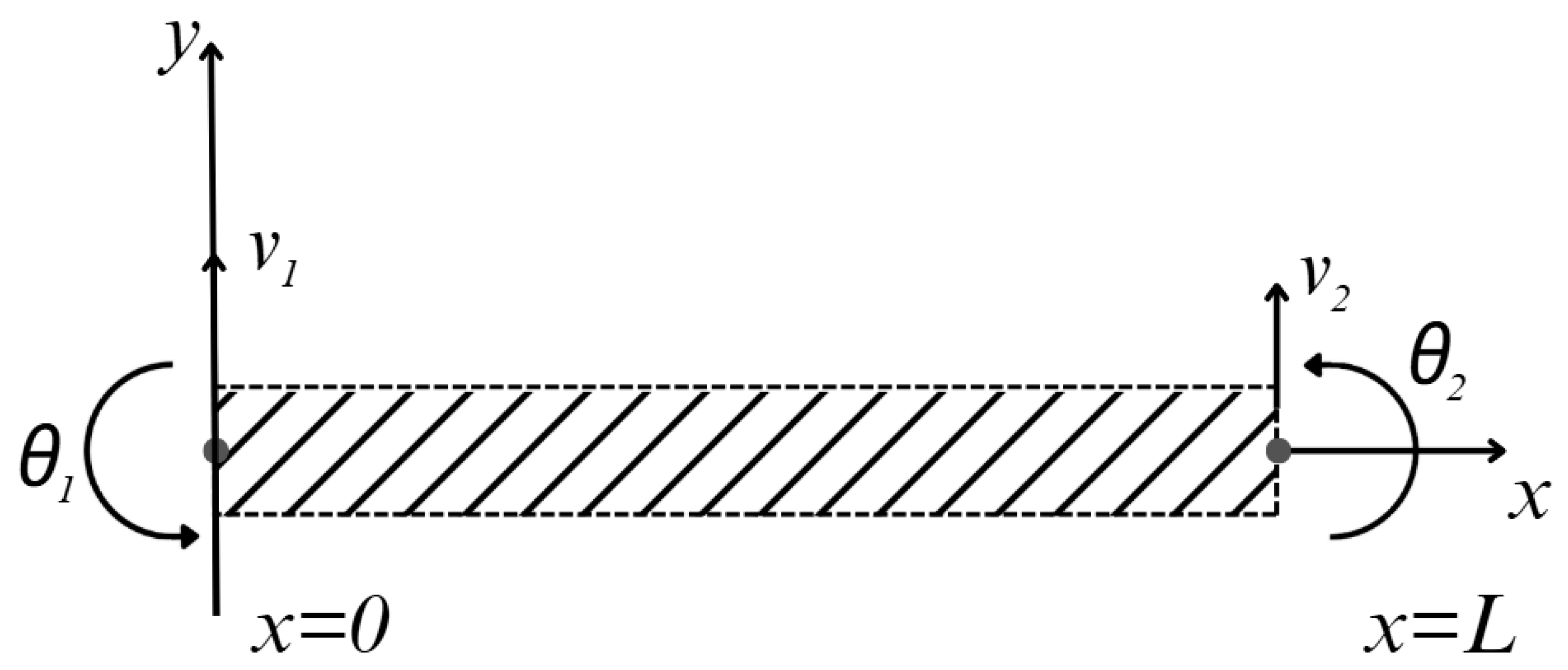
The 2D simplified Bernoulli–Euler beam element is presented in
Figure 2.
Using Hermite shape functions and nodal point vector for the beam element, the transversal displacement of the beam at a point x is approximated [
32]
where
is nodal points displacement vector of the 2D beam element.
By calculating the strain and kinetic energy due to the deformation of the beam, [
33,
34] the 2D beam-element stiffness
and mass
matrices are described.
The finite element discretization leads to the following discretized equation of motion of the undamped free vibration for the global beam system is
Or after (10), by rearranging it, it takes the following eigenvalue problem form:
where
is representing vibration resonant frequencies (eigenvalues) while
ψ is representing vibration resonant modes (eigenvectors). Equation (11) is the state equation solved in the optimization problem for the maximization of the strain at the substructure layer of the cantilever beam by varying thickness
h(
x).
2.2. Optimal Design of Unimorph Substructure
In many structural design problems, first, the eigen frequency often needs to be constrained to the initially given value. So, one more constraint (for a state variable—eigen frequency) is added. An optimal design problem of the cantilever vibration energy harvester can be formulated as follows: to find a vector of design variables h maximizing the objective function (12) and satisfying the equation of state (13) and constraints (14) and (15). The objective function is integral of normal strain on the layer of unimorph substructure.
The general problem of optimal design can be formulated as follows: maximize objective function
with subject to state equation
and constraints
and
where:
—objective function,
h—vector of design variables (thickness of the cantilever in this case),
K(h)—stiffness matrix,
M(h)—mass matrix,
φ—eigenvector of transverse vibration,
ζ—eigen frequency—state variable,
φ and ζ together comprise eigenmode.
Inequality/function (14) in a general problem of optimal design is a constraint for state variables. From the mechanical point of view, it can describe constraints for eigenvalues, strains, stresses, and displacements. The mechanical meaning of the conditions (15) are that all thickness and eigen frequencies of the structure must be positive.
The objective function for maximize normal strain in the upper layer takes the following form:
or in finite element formulation,
where
i is finite element and i = 1,m,
Integrand function (16) is in square due to possible eigenvector sign variation due to the solution of eigenvalue problem (13).
The thickness vector
h of unimorph substructure is a design variable and is limited by finite element thickness:
where
and
are the allowable maximum and minimum element thickness values.
where
The formulated optimization problem was solved using the gradient projection state space method of finite dimensional optimal design with sensitivity analysis for the thickness shape optimization of the unimorph substructure with fixed first eigenfrequency.
2.3. Piezoelectric Coupled Beam
In order to find the electromechanical responses of the piezoelectric beam in an open-circuit condition, the Erturk and Inman [
35] method is used here. The constitutive relation for piezoelectric materials is,
where
is the electrical displacement,
(Coulomb/N or m/V) is the piezoelectric coefficient with polarization in direction 3 due to the external stress in direction 1,
is the axial bending strain along 1-axis,
is the piezoelectric Young’s modulus,
is the permittivity at constant strain,
V(
t) is the electric voltage over the piezoelectric area,
is the thickness of the piezoelectric layer, and
(t) =
V(
t)/
is the electrical field along 3-axis. It should be noted that 1, 2, and 3 directions are aligned with x, y, and z axes, respectively.
The longitudinal bending strain
in the substructure can be calculated as,
where
is the distance between the center of the piezoelectric layer and the beam’s neutral axis and
h is thickness of substructure. Consequently, the electric displacement becomes,
The electric displacement
(
x,
t) is related to the output electric charge
q(
t) by integration over the electrode area as,
It is noted that the piezoelectric layers should cover the whole surface of the beam.
According to Ref. [
36], the capacitance of the piezoelectric is represented by
Cp. Additionally, the goal of this research is to estimate the open circuit voltage across the piezoelectric layers. Hence, the backward coupling in the relations is ignored. Finally, the generated voltage
V(
t) can be calculated as,
2.4. Piezoelectric Beam Discretization
The piezoelectric effect enables conversion between mechanical and electrical energy. When a crystal is deformed, it generates electric polarization proportional to the strain, resulting in a potential difference.
The equations of piezoelectricity combine the momentum PDE (partial differential equation) with the charge conservation PDE of Electrostatics. PDEs for the mechanical field and for the electrostatic field are coupled by the piezoelectric effect. The mechanical field is described by Navier’s equation
where
stands for external volume forces and
a is the vector of inertial forces (material density
and acceleration
a). The dot product of the nabla operator ∇ and the Cauchy stress tensor [
σ] denotes the divergence of the material stresses.
Assuming electrically insulating material and neglecting electromagnetic wave phenomena, Maxwell’s equations for the electric field reduce to
with the electric
flux density
D, the electric charge density
on the electrodes, the electric potential
, and the electric field
E, respectively.
Equations (26)–(28) are coupled by the constitutive equations of linear piezoelectricity.
For the PZT beam it can be formulated with 3-1 mode of piezoelectric constant operation and 3-3 effect of piezoelectric permittivity as,
T1 and S1 represent the vectors of mechanical stress and strain in Voigt notation , and are the material tensors for mechanical stiffness at constant electric field, piezoelectric moduli, and electric permeability at constant mechanical strain, respectively. Combining Equations (26)–(30), we arrive at the coupled PDEs for piezoelectric materials in Voigt notation.
Coupled field piezoelectric equations in primary dependent variables for mechanical displacement
u and electric potential
Ve in piezoelectric medium are as follows:
In the FEM (using Comsol Multiphysics), Equations (33) and (34) are converted into their variational form and the finite element discretized equations for the piezoelectric material are obtained using the standard finite element formulation for the electrostatic equilibrium from Maxwell’s equation, the mechanical equilibrium, and the constitutive relation of piezoelectricity together with the elementary and natural boundary conditions as [
37]
where
,
,
,
, and
represent, respectively, the mass matrix, mechanical damping matrix, mechanical stiffness matrix, piezoelectric coupling matrix, and dielectric stiffness matrix for the piezoelectric material, respectively, while
,
,
,
,
, and
q represent, respectively, the mechanical acceleration vector, the mechanical velocity vector, the mechanical displacement vector, the mechanical external force vector, the electrical potential vector, and the external electric charge vector. Superscript
T stands for the transpose of the matrix.
FEM equations of elements can be derived from (35) and (36) and represent dynamic behavior of piezoelectric material in the following form:
For whole investigated structure, it will be similar. Assembling and computation system of ODE (37) was performed in Comsol, where dependent variables are displacement and electrical potential .
3. Results
3.1. Results of the Optimal Design of the Substructure
To improve the electromechanical efficiency of the piezoelectric energy harvester, the cantilever beam geometry was optimized by adjusting the thickness distribution while constraining the structure to operate effectively at the first natural frequency. Rayleigh damping was applied as a modeling technique to represent energy dissipation within the simulation. The primary design goal was to enhance strain energy concentration in the piezoelectric active layer, thereby increasing the electric polarization and energy output.
The base geometry consisted of a cantilever beam with a length of 100 mm and a constant width of 10 mm. Finite element modeling (FEM) was used for structural optimization, employing 20 bending beam-type elements to discretize the structure. The selected material was Engineering Resin Tough 2000, a homogeneous photopolymer offering stable and repeatable mechanical properties.
The optimization was carried out using the gradient projection method with constraints ensuring that the first eigenfrequency remained within a target range of 21–23 Hz. The final optimized configuration achieved a resonant frequency at 22.2 Hz, with harmonic response analysis indicating a peak electrical output at this frequency.
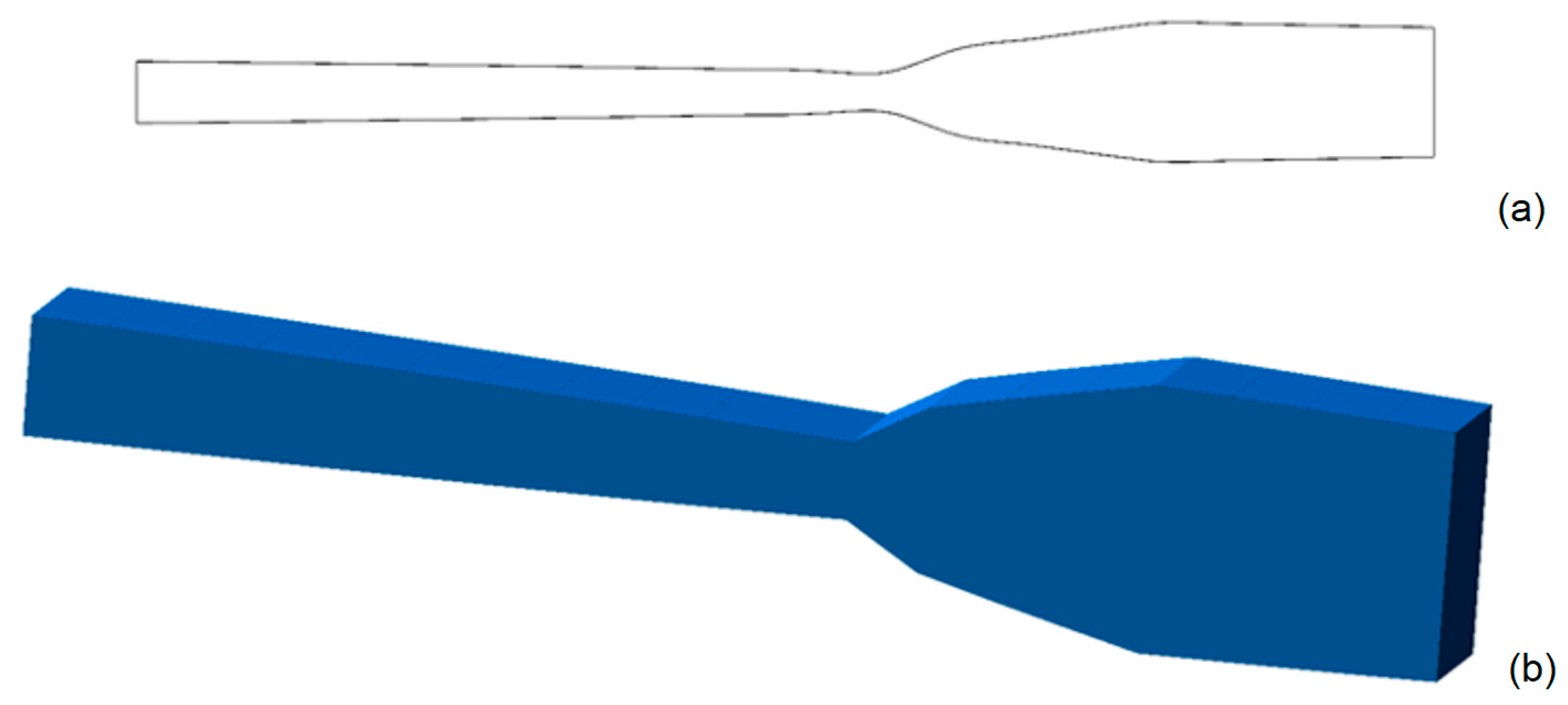
The resulting optimal geometry consists of two functionally distinct sections. The first segment, extending from the clamped base to approximately 0.58 L, exhibits a linear taper from 1.25 mm down to 0.95 mm. This taper promotes a uniform strain distribution in the active region, maximizing the piezoelectric response. The second segment, from 0.58 L to the free end, features a non-linear increase in thickness, reaching 2.14 mm. This section behaves as a distributed inertial mass, enhancing vibrational energy concentration and increasing strain level at the first segment.
The optimal thickness profile is shown in
Figure 3, with panel (a) displaying the plane view and panel (b) displaying the axonometric representation (with thickness exaggerated 2× relative to beam length for clarity).
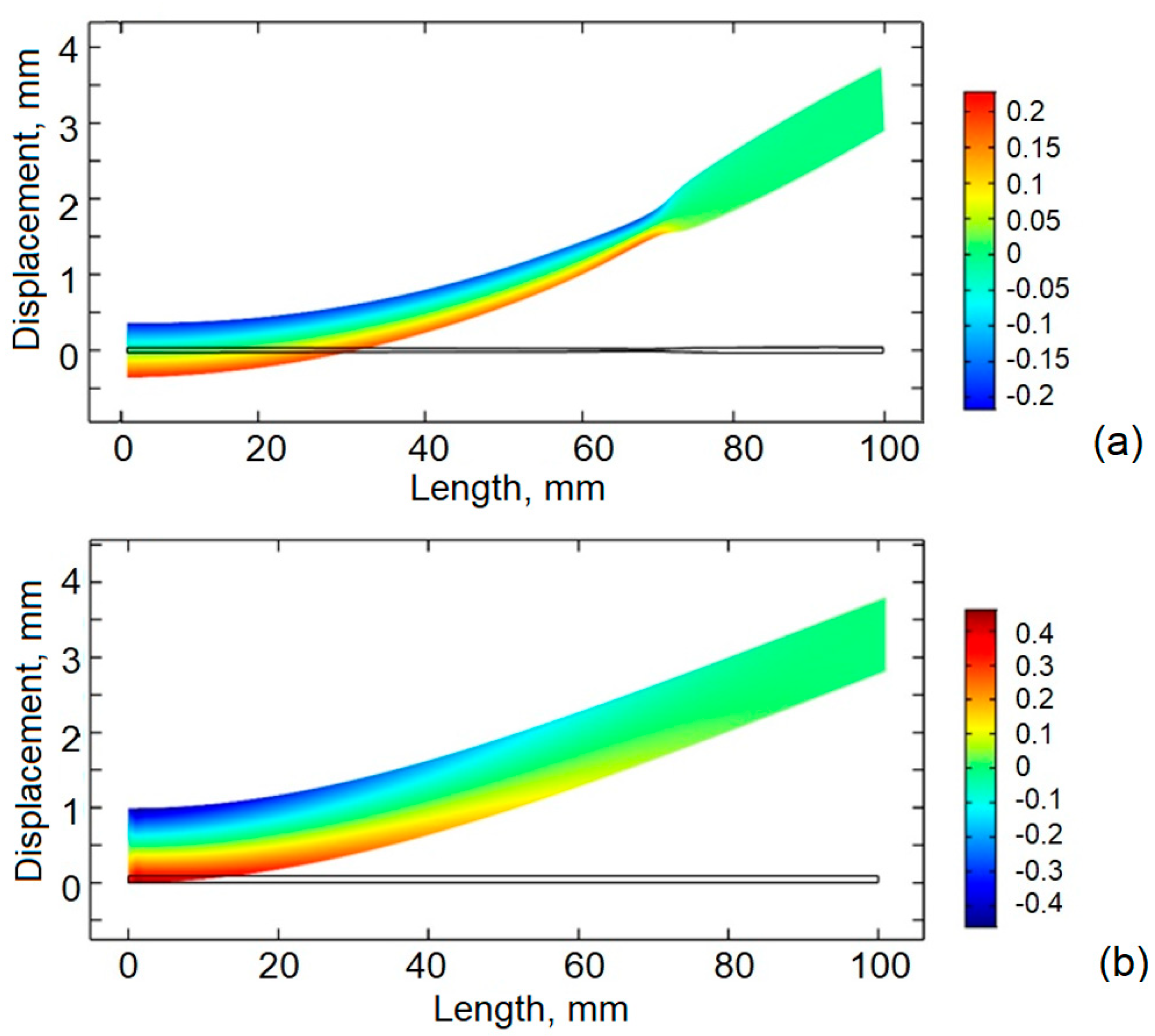
To assess how the optimized geometry enhances strain energy concentration and overall conversion efficiency, the axial strain distribution for the first vibration mode was computed for the optimal design. The resulting strain field is illustrated in
Figure 4, where the optimal shapes’ (picture a) normal strain field is compared to uniform shapes’ (picture b) one. As outlined in the optimization results, the optimal cantilever is divided into two synergistic structural regions.
Uniform shapes cantilever works as expected for a classic cantilever—the largest strain appears at the clamped point of the cantilever.
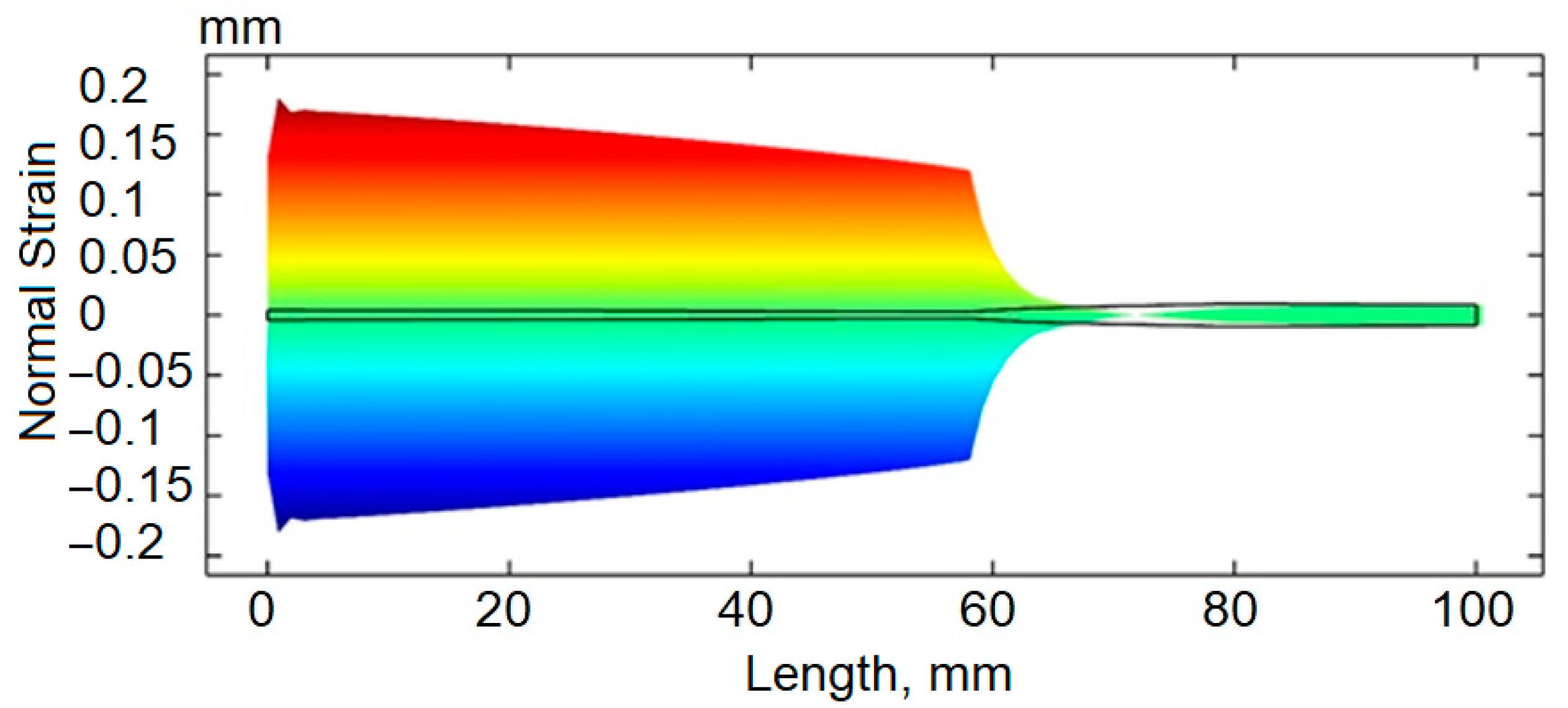
A more detailed distribution of strain along the optimized cantilever is provided in
Figure 5, allowing for a better explanation of the results. The first section of the cantilever, nearest the fixed support, exhibits a modest linear taper and maintains a near-uniform strain along its length. This profile ensures that the active piezoelectric material experiences consistently elevated strain, thereby optimizing electrical output. It is followed by the second segment of the beam—which begins at approximately 0.58 L and extends to the free end—featuring a non-linear increase in thickness. Although this segment is located farther from the strain-intense clamped boundary and may initially appear less effective for energy harvesting, it still plays a crucial role. Its tailored mass distribution significantly enhances dynamic amplification, improving overall performance. Second segment is working as an additional inertia concentration, making the harvester enhance resonance behavior, indirectly increasing strain near the root of the cantilever.
The optimization was carried out using an external routine written by the authors in Fortran. The optimized form was found in 180 iterations. Starting from an initial uniform strain of 0.92 mm thickness cantilever, the objective function improved significantly within the first 40 iterations. This early phase demonstrated a steep optimization gradient, indicative of the algorithm’s strong responsiveness to initial design changes. From iteration 40 onward, the objective function followed a nearly linear trend with minor fluctuations, suggesting diminishing sensitivity as the design approached an optimal configuration.
After 150 iterations, the changes in both strain and frequency values remained within a negligible tolerance band. The eigenfrequency of the optimized design settled at 22.2 Hz, aligning well with the target range of 21–23 Hz. During the optimization path, brief deviations outside the frequency bounds were observed, particularly between iterations 80 and 110, where the frequency temporarily dropped below 20 Hz or exceeded 24 Hz in isolated instances. However, these deviations were self-correcting due to the frequency constraint mechanism embedded in the optimization model.
While shortening the length of the high-strain active segment might suggest a potential performance loss, this is more than compensated for by the beneficial inertial effects of the mass-enhancing tail section. Together, the segments work in tandem to achieve superior performance under resonant excitement. The resulting design allows for more effective energy harvesting at the first eigenfrequency.
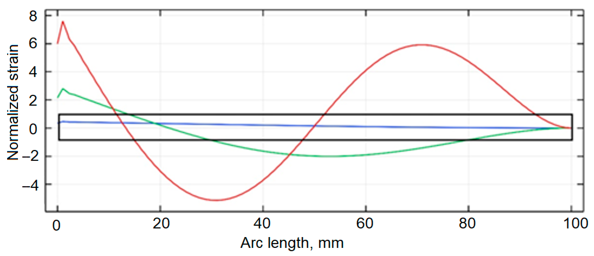
Figure 6 illustrates the normalized axial strain distributions for the first three vibration modes of a uniform-thickness cantilever beam. The strain patterns are shown using three colors: blue for the first mode, green for the second, and red for the third.
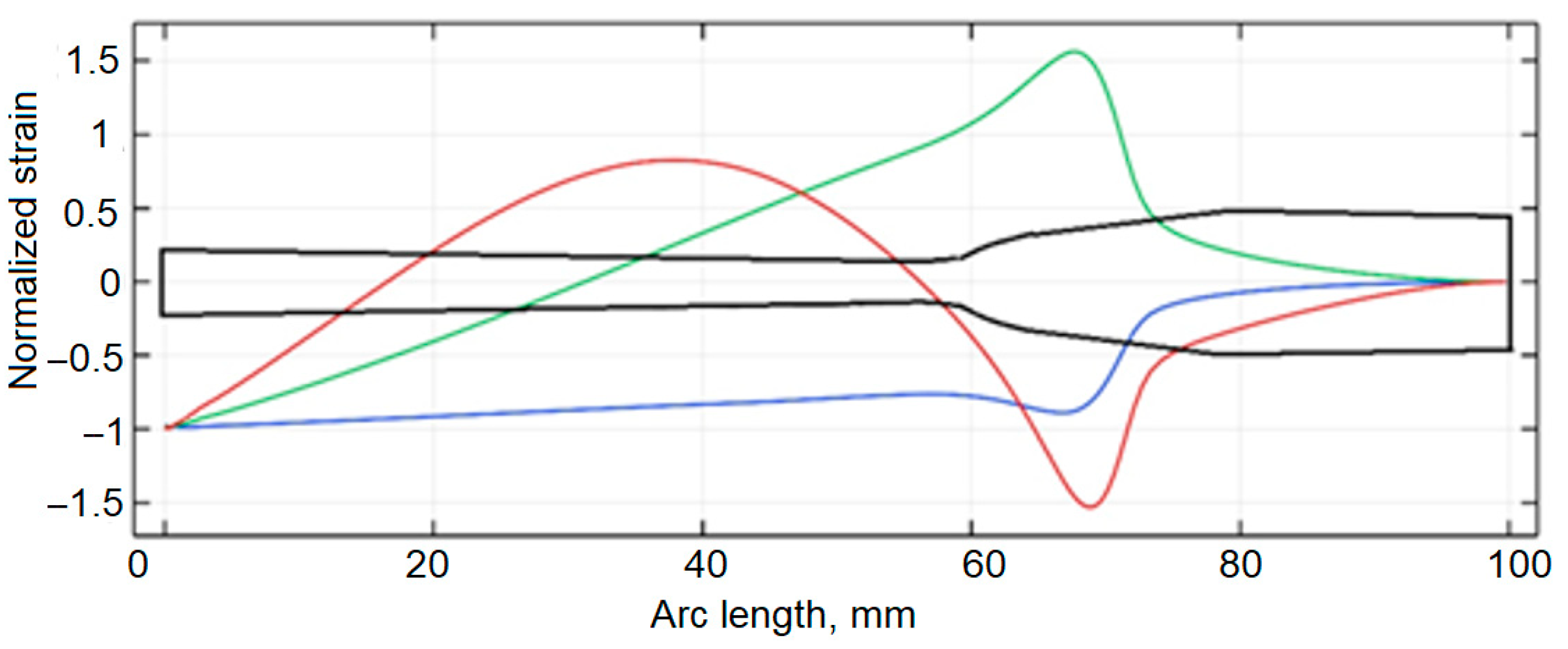
Figure 7 presents the strain distribution for the cantilever beam with optimized thickness. As in the previous figure, the first three modes are represented by same colors. The strain mode of the first eigen frequency is a classical example for the uniform cantilever; however, in optimal, it is linear from 0 to around 58 mm of the cantilever and later switches to a non-linear pattern. The green line, representing the second mode, is a curved line for the uniform cantilever shape, but in the optimized one, it is straight from the beginning, till 58 mm of length, later turning into non-linear. Also, it is important to mention that the node for this moved from 20 mm from the beginning in uniform to 30 mm in the optimal shape cantilever. Red line, representing third mode, has nodes in 17 mm and 50 mm in uniform shape, which switches to 18 mm and 58 mm in the optimal shape cantilever.
A transient dynamic analysis was conducted to evaluate the time-dependent strain behavior of the optimized cantilever configuration relative to a beam with uniform thickness.
Figure 8 presents a comparative profile of the integrated axial strain along the upper surface of both designs when subjected to harmonic base excitation at their respective first natural frequencies. Although the axial strain values are dimensionless by definition, their integration over the cantilever length results in a metric value with units of meters, representing the cumulative deformation experienced by the active material layer.
The strain evolution curves reveal a marked improvement in the deformation characteristics of the optimized geometry. The uniform-thickness cantilever exhibits a peak integrated strain of approximately 2.2 × 10⁻⁶ m. In contrast, the optimized profile achieves a significantly higher peak value of 3.0 × 10⁻⁶ m, indicating superior strain energy capture over the excitation cycle. This enhancement underscores the effectiveness of the thickness optimization strategy in concentrating strain energy within the piezoelectric layers, thereby facilitating greater electromechanical conversion efficiency during vibrational excitation.
3.2. Results of the Distributed Optimal Design Piezoelectric Cantilever Simulation
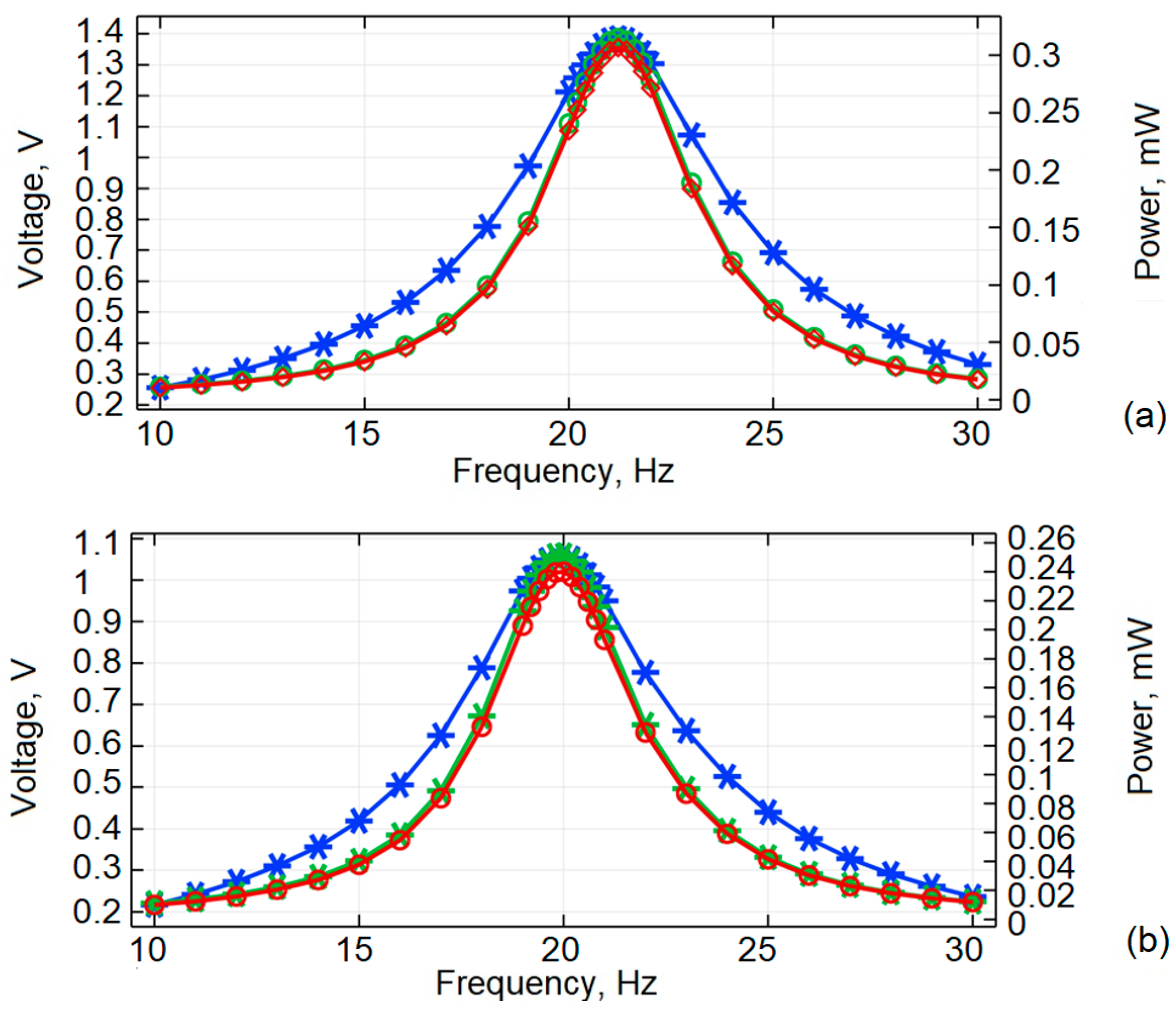
Further investigation was performed by conducting a simulation on the optimal design piezoelectric cantilever beam. The analysis was conducted as previously, by comparing the optimal shape (in a) piezoelectric cantilevers response to uniform cantilevers results (in b) in
Figure 9.
From the graphs it can be seen that optimal shape cantilever has a maximum voltage generation of 1.4 V at 21.5 Hz. Compared to the uniform cantilever response which is in a broadband of 20–23 Hz, but peaks at 20 Hz and is equal to 1.07 V. A clear difference of ~30% improvement in electrical potential value for optimal shape cantilever. Comparing mechanical power, optimal shape cantilever generates 0.32 mW at 21.5 Hz, uniform—0.25 mW. Electric Power generation results in 0.3 mW for Optimal and 0.24 mW for uniform shape cantilever. First, the power output is analyzed as a function of vibration frequency, with a fixed electrical load. The electrical load is 35 kΩ.
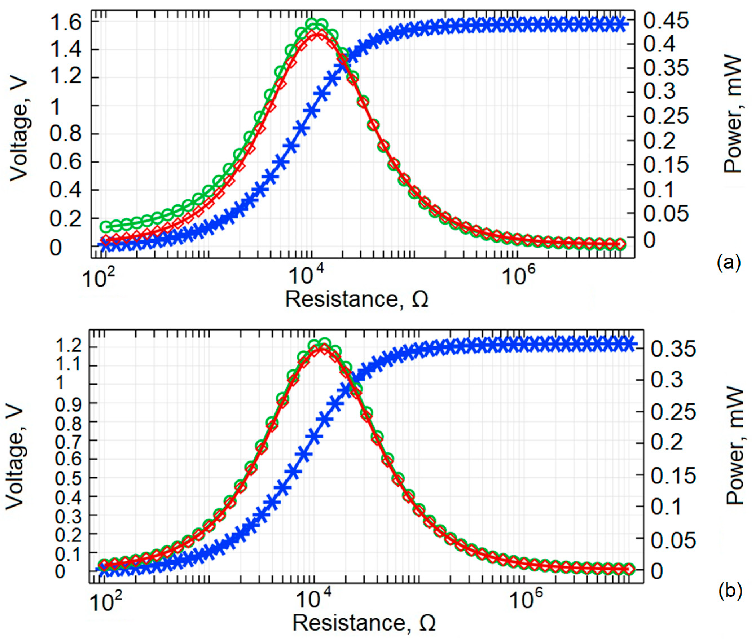
From
Figure 10, it is clear that the load dependency is from 10
2 Ω to 10
7 Ω. The peak in energy harvested corresponds to an electrical load of 12.5 kΩ for unimorph of the optimal thickness and 10.1 kΩ for constant thickness unimorph.
The modeling and simulation results demonstrate the performance advantages of the optimized cantilever design in both structural and functional terms. The distributed thickness profile ensures compliance with both geometric and frequency constraints. Additionally, it substantially enhances energy harvesting performance, particularly by increasing voltage output and improving strain localization. Despite slight differences in electrical power under load variation, the optimized beam consistently exhibits higher voltage generation, better strain distribution, and more efficient resonance behavior.
Overall, the results confirm that structural optimization—specifically through gradient-based thickness shaping—provides a reliable and effective strategy for enhancing the electromechanical performance of cantilever-type piezoelectric energy harvesters operating in low-frequency environments.
4. Experimental Review
To assess the accuracy of the numerical model and verify the performance gains of the optimized cantilever geometry, two complementary experiments were conducted. The first involved non-contact amplitude–frequency analysis using a multipath interferometry system to validate the predicted eigenfrequencies. The second experiment employed controlled base excitation to compare the electrical response of optimized and uniform cantilevers under identical loading conditions. Together, these methods provide a comprehensive evaluation of the harvester’s dynamic and electromechanical behavior.
Two types of cantilever specimens—one with a uniform cross-section and one with an optimized thickness profile—were designed for the same eigen frequency and fabricated using high-precision additive manufacturing. The components were produced on a Formlabs Form 3 L stereolithography system (Formlabs, Somerville, MA, USA), enabling an accurate reproduction of both geometries. Consistent with the numerical model, all specimens were manufactured from Engineering Resin Tough 2000, a photopolymer selected for its uniform mechanical response and reliable post-curing characteristics. The material exhibits a tensile modulus of 2.2 GPa, a Poisson’s ratio of 0.41 [
38], and a density of 1110 kg/m
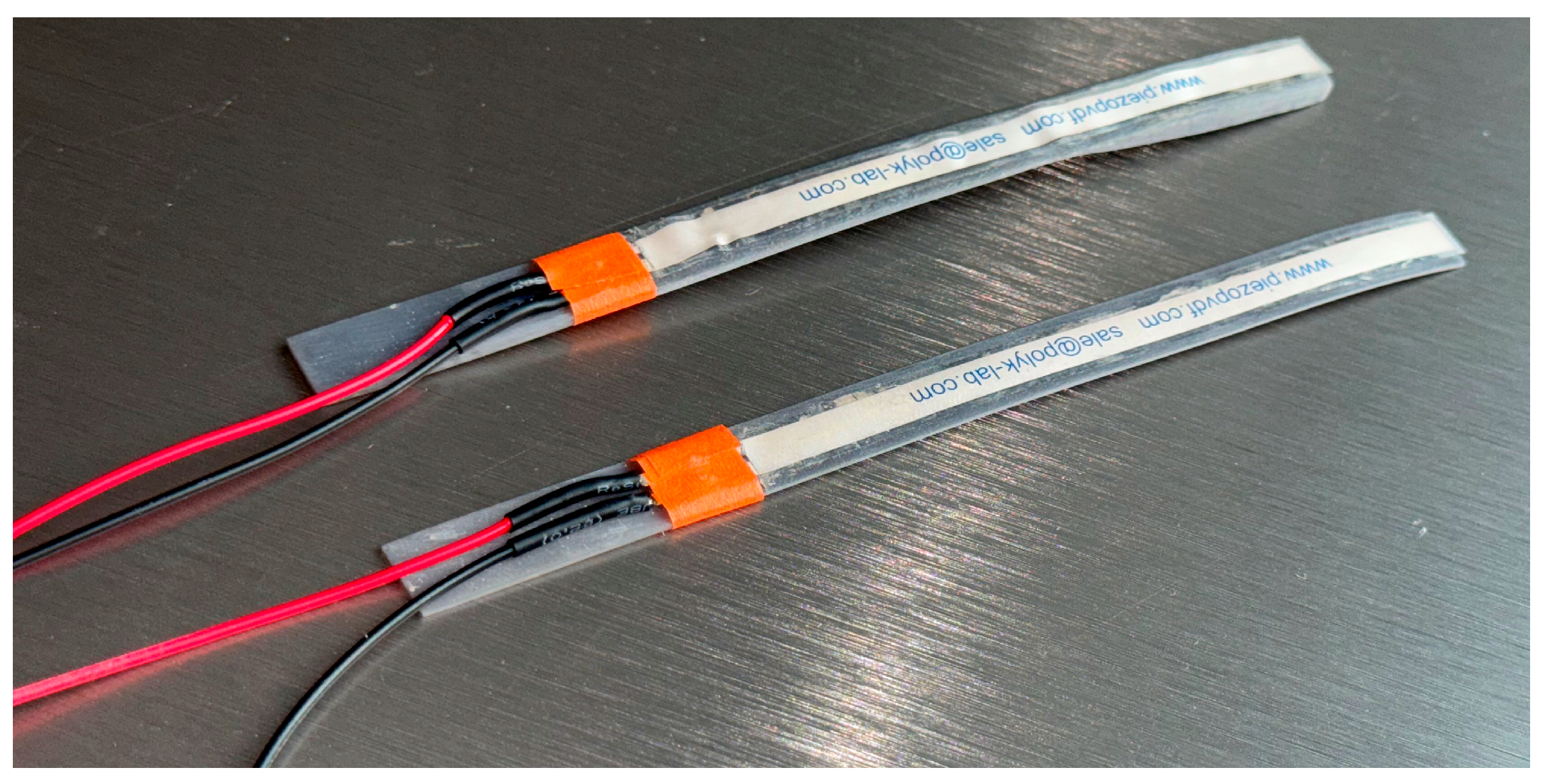
3. A uniform cantilever beam has a constant cross-section of 0.9 mm, while the optimal shape cantilever features a thickness ranging from 0.95 mm at the clamped root to 2.14 mm at the free end, as defined by the optimized shape function. Both designs shared the same in-plane dimensions—100 mm in length and 10 mm in width—to isolate the effects of thickness shaping on vibrational behavior and energy conversion. The piezo layer was 28 μm PVDF DT1-028K/L (PolyK Technologies, State College, PA, USA) stuck on to the cantilever upper layer with contacts stretching out for electrical signal transmission (
Figure 11).
The optimized cantilever geometry, as detailed in the methodology section, consists of a slightly tapered linear profile extending up to 60% of its length from the clamped end. Beyond this point, the structure transitions into a non-linearly distributed inertial mass region. In contrast, the second cantilever maintains a uniform thickness along its entire length, with no geometric variation. Despite the structural differences, both cantilevers exhibit similar fundamental eigenfrequencies. The piezo layer is the same length as cantilevers, with an 8 mm width.
4.1. A Multipath Interferometry Analysis for Amplitude—Frequency Response
The principal layout featuring real life photos of the experimental setup is presented in
Figure 12. The setup comprised several key components, including a computer with dedicated software, a controller unit (Polytec, Irvine, CA, USA), a signal amplifier F10A (FLC Electronics, Partille, Sweden), a cantilever beam specimen clamped securely, and the 3D laser vibrometer camera system PSV QTec 3D (Polytec, Irvine, CA, USA).
The experimental procedure involved applying a series of short bursts of sinusoidal base excitation across a frequency range of 0 Hz to 1000 Hz to the cantilever by means of the piezoelectric layer. The laser interferometry system measured the resulting eigen frequencies, capturing its dynamic response throughout the entire frequency spectrum.
A total of 114 measurements were conducted over an area of 1000 mm2 for each cantilever. The resulting data is presented in 3D models, accurately reflecting the eigen frequencies recorded at each specified data point along the cantilever during the experiment. Additionally, this clearly illustrates areas where changes in acceleration occur.
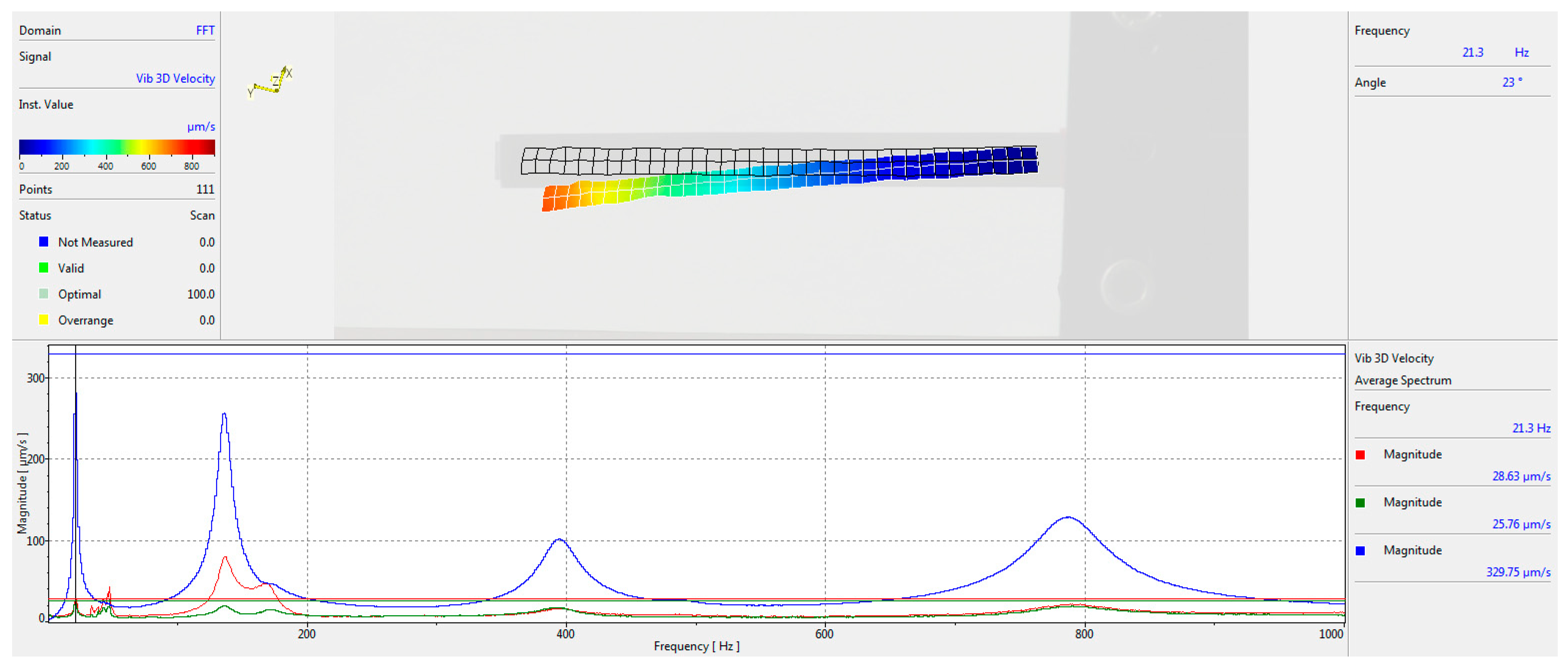
The results of the experiment for the initial shape cantilever oscillating in its first eigen frequency are shown in
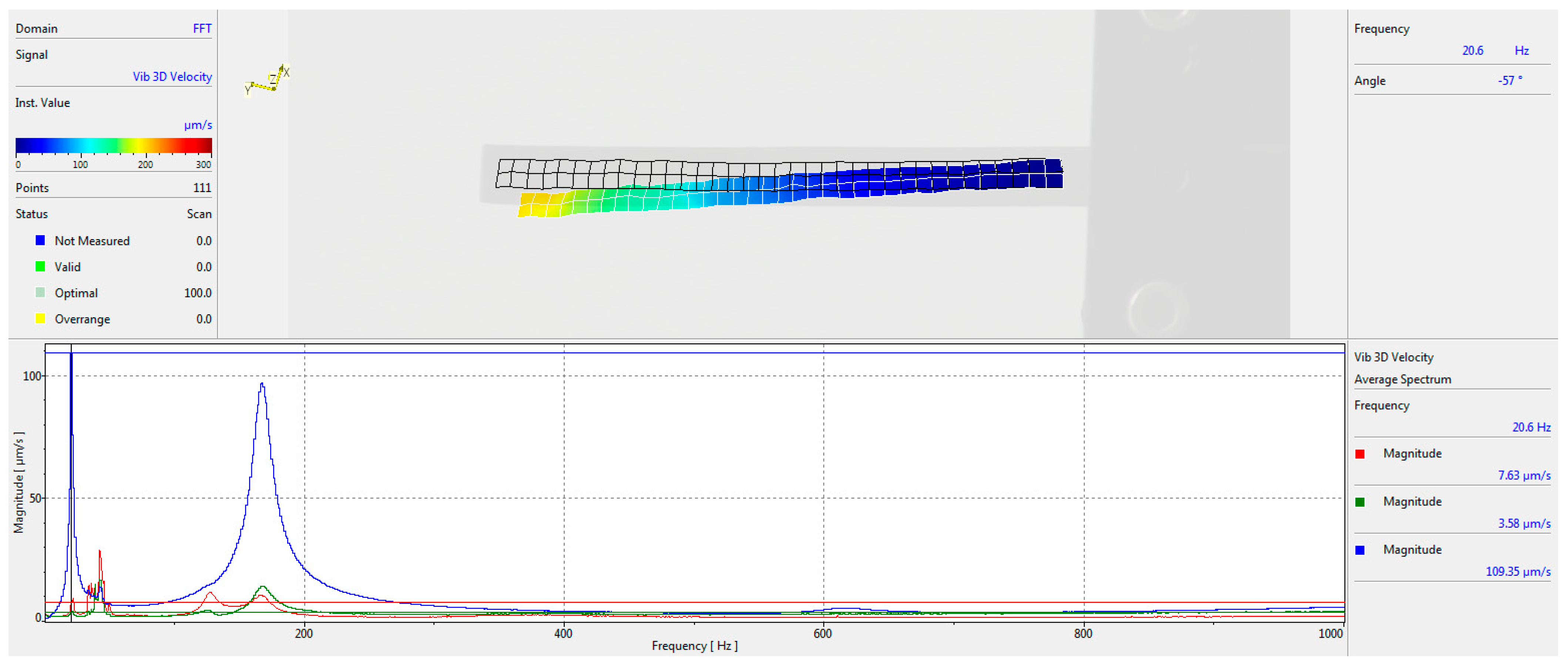
Figure 13, and for the optimal shape in
Figure 14. The graphs depict magnitudes in µm/s in each axis, with blue color representing the Z axis (the main axis for amplitude measurement), red—Y axis, and green—X axis.
The experiment yielded a fundamental frequency of 21.6 Hz for the initial cantilever shape and 20.6 Hz for the optimized shape. The difference of approximately 4.85% confirms that the optimized cantilever shape is sufficiently close to the initial design in terms of frequency characteristics. The Multipath Interferometry Analysis conducted using the Polytec 3D laser system effectively validated the eigen frequencies of the cantilevers developed through mathematical modeling, including both uniform and optimized shapes, across a wide frequency spectrum. The experimental setup facilitated the measurement of the eigen frequencies, revealing distinct resonance peaks for each design.
4.2. Electromechanical Response Characterization Under Controlled Base Excitation
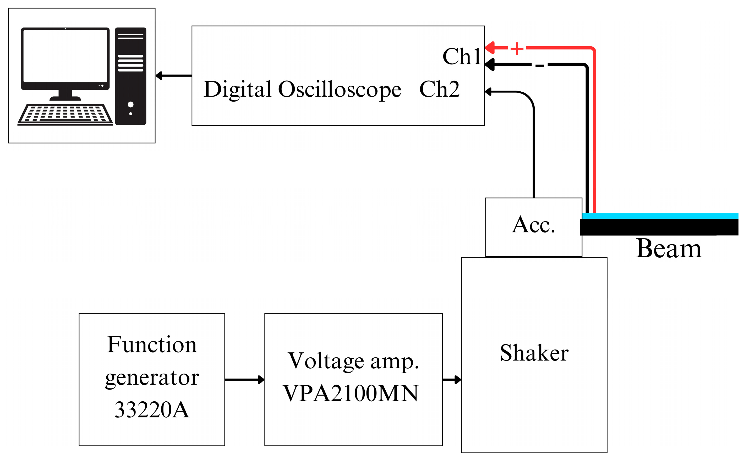
The other evaluation was conducted using the constant excitation technique, where a vibrating platform was used for cantilever excitation. In this configuration, the piezoelectric cantilever operated as a sensor, contrasting with its role as an actuator in the initial test setup. Each cantilever was attached to the shaker through a clamping mechanism, and excitation signals were managed using a 33220A function generator (Keysight, Santa Clara, CA, USA). To improve the accuracy of the readings, the output signal was boosted using a VPA2100MN voltage amplifier (HQ Power, Gavere, Belgium). A KS-93 single-axis accelerometer, with a 5 mV/(m/s
2) sensitivity rating, was used to monitor excitation levels. The output from the accelerometer, laser control unit, and piezoelectric sensors was collected using a 4224 USB oscilloscope and processed on a computer via Picoscope software (Picoscope 6, Version 6.14). The complete experimental setup is illustrated in
Figure 15.
The outcomes obtained from this second setup are displayed in
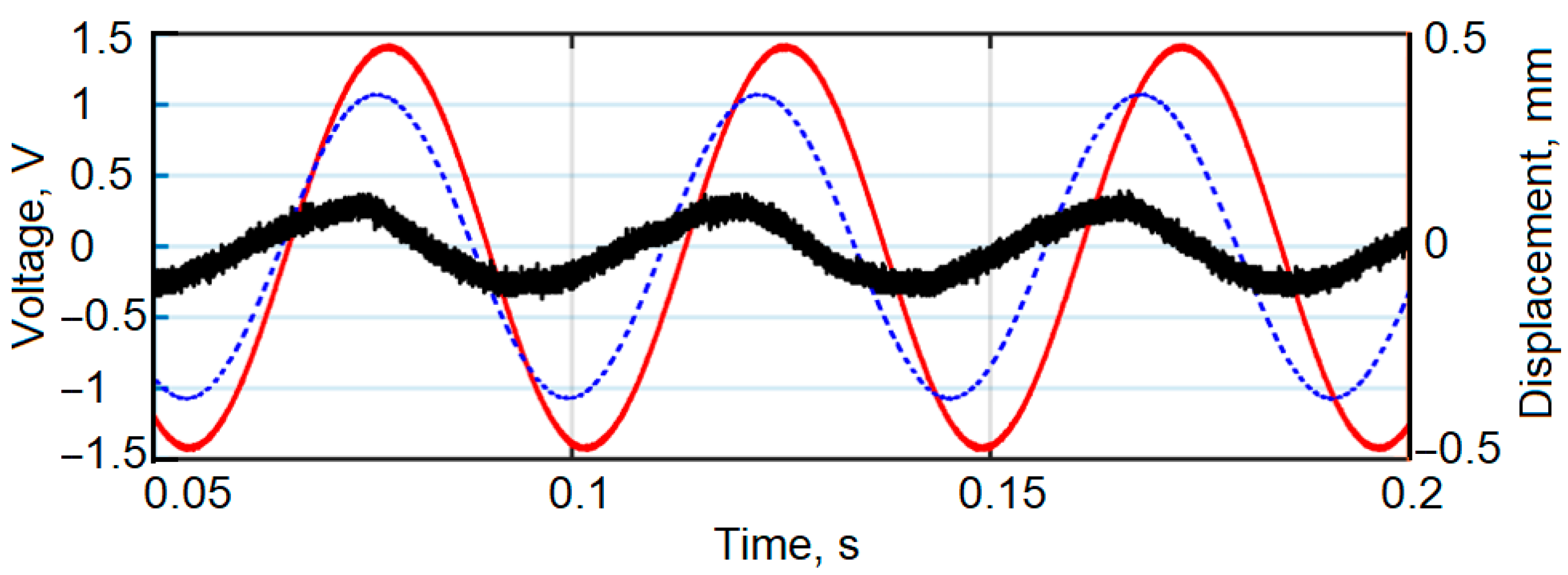
Figure 16, comparing the excitation acceleration of the vibrating plate with the voltage signals produced by cantilevers, which were operating under open-circuit conditions.
Analysis of the data reveals that the cantilever with the optimized geometry demonstrated approximately 30% greater efficiency, generating a 1.4 V signal, whereas the standard uniform cantilever reached only 1.07 V. The excitation acceleration remained constant at 14 m/s2 for both configurations.
Experimental measurements and statistical analysis of the voltage generated by unimorph were performed. During the experiment, the unimorph cantilever base of optimal thickness and constant thickness was excited at the first resonance frequency and the generated voltage was measured. The electrical load was 35 kΩ. Before each measurement, the unimorph cantilever wires were reconnected to the digital oscilloscope, and the unimorph cantilever wires were reattached to the vibrational plate. This was repeated 8 times. The measurement results are presented in
Table 1.
At first, the main statistical parameters for both unimorph cantilevers were calculated. Results are presented in
Table 2.
Because such processes generally have Gaussian distribution, the use of the 2 × σ rule is possible and with 95% probability, the optimal thickness unimorph will generate voltage in the interval 1.27 V–1.53 V. For the constant thickness unimorph this interval is 1.03 V–1.11 V.
The experimental investigation effectively confirmed the accuracy of the numerical eigenfrequency predictions and demonstrated the advantages of optimized cantilever geometry. The laser-based multipath interferometry system enabled high-resolution frequency analysis without interfering with cantilever dynamics. The optimized design not only matched the target eigenfrequency within a 5% margin but also exhibited approximately 30% higher electrical response under first resonant excitation. These results validate the reliability of the numerical model and highlight the improved performance of the optimized cantilever in vibration energy harvesting applications.
5. Conclusions
This study proposed and validated a gradient-based optimization framework for the thickness distribution of cantilever piezoelectric energy harvesters, constrained to maintain a prescribed first eigenfrequency. The optimized geometry, characterized by a linear taper from 0.95 mm to 1.25 mm across 58% of its span and a non-linear increase to 2.14 mm at the free end, achieved a fundamental resonance of 22.2 Hz—closely aligning with the uniform of 20 Hz. Compared to a conventional uniform-thickness beam, the optimized configuration yielded a 36% increase in integrated strain magnitude (from 2.2 × 10⁻⁶ m to 3.0 × 10⁻⁶ m) under base excitation.
Two independent experimental setups were employed for empirical validation. In the first, a non-contact laser vibrometry system (Polytec 3D) was used to characterize the dynamic behavior of stereolithographically fabricated specimens. The measured fundamental frequencies of 20.6 Hz (optimized) and 21.6 Hz (uniform) confirmed simulation predictions and manufacturing precision within 5%. The second experiment used a first resonant base excitation setup, where the optimized cantilever generated a 1.4 V signal, compared to 1.07 V for the uniform design, under a matched acceleration of 14 m/s2—representing an approximate 30% gain in experimental voltage output. This directly confirms the predicted improvements in energy harvesting efficiency due to optimized geometry.
This work contributes to the existing literature by demonstrating that non-linear thickness shape optimization, unlike more commonly studied width variation, can significantly enhance strain localization and electrical output while preserving the original eigenfrequency. The demonstrated gain in voltage output, achieved without shifting resonance characteristics, marks a notable advancement in the structural optimization of piezoelectric harvesters. While this research focused on optimizing the geometry for the first eigenfrequency, the same approach could be extended to higher-order modes, such as the second or third eigenfrequency, to support future multimode or broadband energy harvesting applications.
In conclusion, the proposed thickness optimization methodology significantly improves the performance of cantilever piezoelectric energy harvesters in low-frequency applications. The strong agreement between numerical and experimental results confirms the robustness and manufacturability of the approach. These findings highlight the potential of geometric tailoring as a scalable and effective design strategy for enhancing energy conversion in self-powered sensing, IoT nodes, and structural health monitoring systems.


