Article

Comprehensive Study of the Mechanical and Tribological Properties of NiCr-Al Detonation Coatings

1
Research Center «Surface Engineering and Tribology», Sarsen Amanzholov East Kazakhstan University, Ust-Kamenogorsk 070002, Kazakhstan
2
PlasmaScience LLP, Ust-Kamenogorsk 070018, Kazakhstan
3
Department of Machine Design and Maintenance, Faculty of Mechanical Engineering and Robotics, AGH University of Krakow, al. A. Mickiewicza 30, 30-059 Krakow, Poland
*
Author to whom correspondence should be addressed.
Appl. Sci. 2025, 15(13), 7513; https://doi.org/10.3390/app15137513
Submission received: 8 May 2025 / Revised: 13 June 2025 / Accepted: 18 June 2025 / Published: 4 July 2025
(This article belongs to the Special Issue Corrosion and Protection with Hard Coatings)

Abstract

This article presents a comprehensive study of the mechanical and tribological properties of detonation coatings in the NiCr-Al system. Using the detonation spraying technology, NiCr-Al homogeneous (HC) and gradient coatings (GCs) were produced, and their characteristics were determined. Modern analytical instruments were used in the course of the study. The results showed that the microhardness of the NiCr-Al GC was approximately 30% higher compared to the NiCr-Al HC. According to nanoindentation results, the elasticity modulus and nanohardness of the NiCr-Al GC were twice as high as those of the NiCr-Al homogeneous coating. Tribological tests conducted using the rotational ball-on-disk contact geometry showed that the wear rate of the NiCr-Al GC was significantly lower, while the friction coefficients of both coatings were approximately similar. According to the adhesion strength tests, the strength of the NiCr-Al GC was recorded at 38.7 ± 6.9 MPa, while that of the NiCr-Al HC was approximately 25.4 ± 3.1 MPa. High-temperature tribological tests revealed that the wear resistance of the NiCr-Al GC was 2.5 times higher than that of the NiCr-Al HC. The conducted studies demonstrated that the coating structure, particularly the distribution of elements, has a significant influence on its mechanical and tribological properties. Overall, the NiCr-Al GC exhibited superior mechanical and tribological performance.

1. Introduction

NiCr-Al-based coatings are widely used in devices such as gas turbines, valves, and heat generation systems in the energy sector due to their high-temperature resistance [1,2,3]. In such environments, NiCr-Al coatings are subjected to erosion and frictional wear caused by solid particles and high-velocity gas flows during operation. Under these aggressive conditions, the structural stability and wear resistance of NiCr-Al coatings play a critical role. Numerous studies have been carried out on the mechanical and tribological properties of NiCr-Al-based coatings [4,5,6]. For example, in one study by Liang and Su [7], it was found that Ni-rich amorphous structures and Ni3Al crystallites formed in laser-clad NiCr-Al coatings on aluminum alloys. Furthermore, the influence of the amorphous structure on tribological performance was investigated, and it was demonstrated to significantly enhance wear resistance. The study revealed that increasing the amorphous fraction from 2.18% to 31.1% resulted in a nearly 3.6-fold reduction in wear volume. In another investigation, Yang et al. [8] investigated the microstructure, friction coefficient, and wear rate of Ni-7Cr and Ni-7Cr-2Al nanocomposite coatings. The results of the study showed that the significant improvement in the microhardness and wear resistance of the coating due to Al nanoparticles was attributed to the formation of amorphous oxides on the surface and the dispersion strengthening effect of Al2O3 nanoparticles. Additionally, Zhao et al. [9] conducted electrochemical tests on NiCr-Al coatings and found that the coatings exhibited high corrosion resistance. Therefore, a comprehensive understanding of the phase structure, as well as the high-temperature, mechanical and tribological properties of NiCr-Al coatings, is essential for expanding their potential applications in demanding service environments.
Currently, various deposition methods are used to produce NiCr-Al coatings. In the works of Huijuan Zhen and Xiao Peng [10,11], Cr-Al nanoparticles were first embedded onto the surface by electrophoretic deposition (EPD), resulting in the formation of a porous layer. Subsequently, an Ni layer was introduced into this porous structure using the electrodeposition method. As a result, a uniform, dense, and oxidation-resistant NiCr-Al nanocomposite coating was obtained. These coatings were able to form an aluminum oxide (Al2O3) layer in air at 1000 °C, and their oxidation resistance improved depending on the Cr and Al content in the coating. In another study, Huijuan Zhen et al. [12] produced Ni-16Cr-14Al nanocomposite coatings by combining electrophoretic deposition (EPD) and electrodeposition methods. Subsequently, the coatings were tested for oxidation resistance at 800 °C in humid air containing 10% H2O. According to the research results, a two-layer oxide scale consisting of an outer NiAl2O4 layer and an inner α-Al2O3 layer was formed on the coating surface. The NiCr-Al coating significantly improved the oxidation resistance of steel in humid air [12].
One of the most promising and rapidly developing approaches in recent years for producing NiCr-Al-based coatings is the thermal spraying technology. In particular, high-velocity oxy-fuel (HVOF) spraying, plasma spraying, and detonation spraying methods are widely used for the deposition of NiCr-Al-based coatings. NiCr-Al coatings produced by the HVOF method are characterized by high density, structural homogeneity, and excellent mechanical strength. Mahesh R.A. et al. [13,14,15] investigated the hot corrosion resistance of NiCr-Al coatings produced by the HVOF method in the low-temperature superheater zone (approximately 700 °C) of a coal-fired boiler. The results showed that the NiCr-Al coating formed a dense and stable oxide layer, acting as a reliable barrier against hot corrosion. Daniel Aristu et al. [16] conducted a comprehensive study on the high-temperature corrosion resistance of NiCr-Al coatings produced by thermal spraying methods such as atmospheric plasma spraying (APS) and high-velocity oxy-fuel (HVOF). In the study by Celik E. et al., the corrosion resistance of NiCr-Al coatings obtained by APS was evaluated as moderate [17]. Vassilis Stathopoulos et al. [18] used the detonation spraying method to fabricate functionally graded multilayer TBC for gas turbines. In this approach, both the Yttria-Stabilized Zirconia (YSZ) ceramic layer and the bond coat were deposited by detonation spraying, while the top nanocomposite oxide layer was applied using the slip casting (SC) method. The results of thermal resistance testing at 1200 °C showed that the detonation-sprayed TBC exhibited good adhesion and compatibility between all coating layers, with no signs of delamination or cracking.
Over the past two decades, various techniques for synthesizing NiCr-Al-based coatings have been developed, alongside in-depth investigations into their structural properties. Among the explored methods, gradient coatings (GCs) have gained attention as a highly promising approach [19,20,21,22]. Functionally graded coatings (FGCs) allow for a gradual transition in composition and properties through the coating thickness, enhancing thermal stability, mechanical strength, and resistance to wear and corrosion [23,24,25]. One of the key challenges in traditional homogeneous coatings is the accumulation of thermal and residual stresses during service, which FGCs are particularly well-suited to mitigate [26,27]. Their ability to tailor material properties across the cross-section makes them a practical solution for demanding operational conditions [28,29]. The aerospace industry has especially benefited from FGCs, where they contribute to improved component lifespan, enhanced material performance, and reduced maintenance needs [30]. For example, NiCrAlY and 8YSZ gradient coatings applied to Inconel 718 substrates via atmospheric plasma spraying (APS) have demonstrated improvements in thermal performance [31]. Furthermore, Yuan et al. [32] examined how different deposition strategies—thermal oxidation, laser texturing, and their combination—affect the mechanical and tribological properties of titanium dioxide-based gradient coatings on Ti-6Al-4V alloys. Their study found that the hybrid approach produced coatings with significantly enhanced hardness and elasticity, reducing wear by up to 95%, thereby demonstrating the effectiveness of graded architectures in high-performance applications.
One of the emerging and promising technologies for producing gradient coatings (GCs) is the detonation spraying method [18,33,34,35]. In this context, we conducted a study in collaboration with our co-authors, focusing on the fabrication of GC using this technique [36,37,38,39,40]. A gradient coating based on the NiCr-Al system was successfully produced via detonation spraying [41], and the process is protected by a utility model patent [42]. The obtained GC NiCr-Al coating was evaluated for high-temperature oxidation resistance, and the results demonstrated superior protective performance compared to its homogeneous counterpart (HC NiCr-Al) [43].
This study aims to evaluate the feasibility and advantages of gradient NiCr-Al coatings by comparing their mechanical properties with those of homogeneous coatings, thereby elucidating the influence of coating architecture.

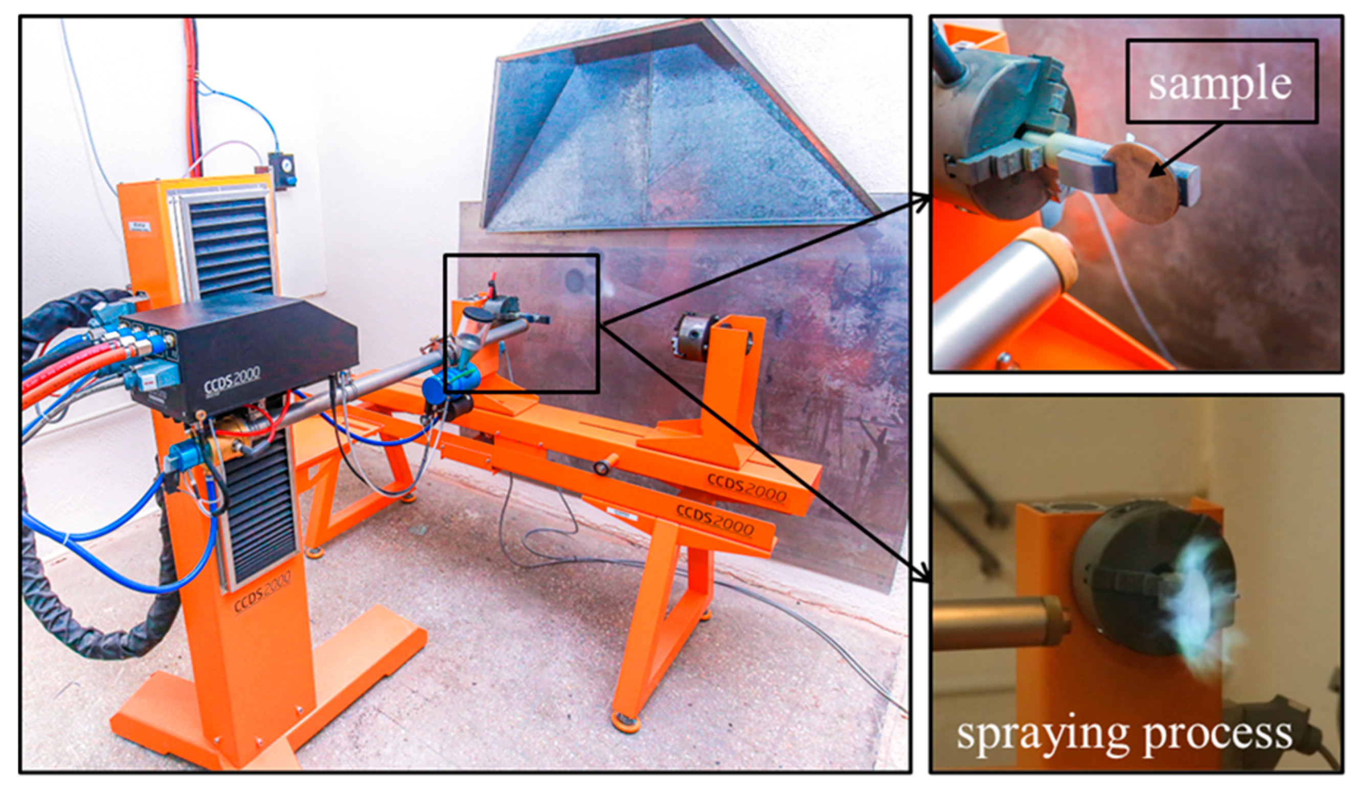
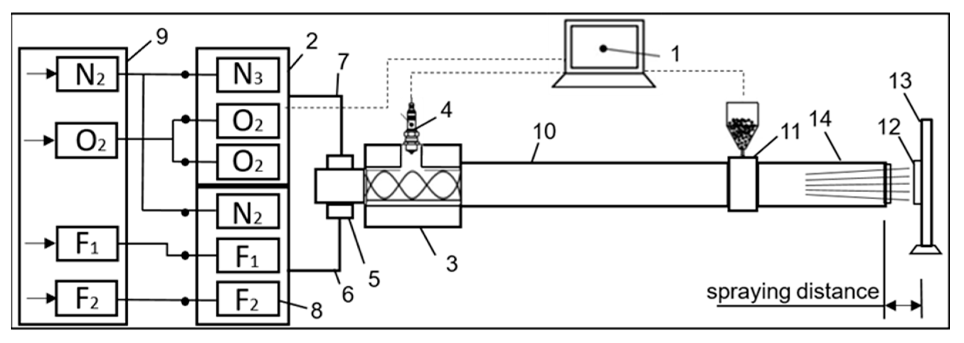
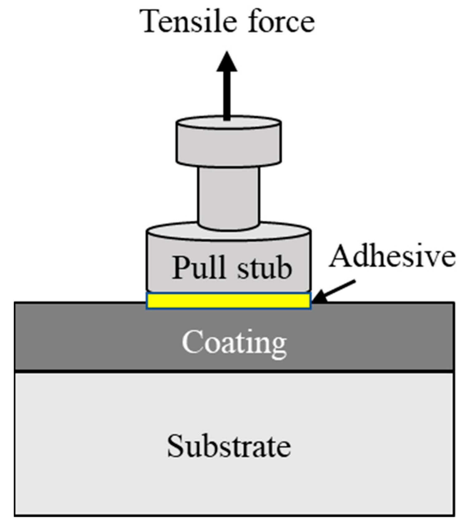
2. Materials and Methods

For the deposition of NiCr-Al coatings, 14MoV6-3 low-alloy steel was selected as a substrate (according to ISO 4955) [44]. For substrate preparation, 14MoV6-3 steel was cut into discs with a diameter of 50 mm and a thickness of 3 mm. Prior to coating deposition, the surface of the substrate samples was ground using abrasive papers up to grit size 1000, followed by sandblasting to enhance the mechanical interlocking and adhesion strength of the coating. Polishing up to grit size 2000 was applied to the cross-sectional samples prepared for microstructural analysis.
To prepare the composite powders, Ni75Cr25 powder and Al powder with a purity of 99.99% were used. A BML-6 ball mill was used for mixing the powder blend and performing mechanical activation. The mechanical activation was carried out for 2 h at a vibration frequency of 30 Hz. Figure 1 shows the morphology and particle size distribution of the NiCr-Al (20 wt.%) composite powder obtained by scanning electron microscopy (SEM) (TESCAN MIRA3 LMH (TESCAN, Brno, Czech Republic). The particle size of the powder was determined from the SEM images using ImageJ software (version 1.54). The measurements were conducted on three SEM images taken at 100× magnification. The average particle size and standard deviation were calculated based on the measurements of individual particles.
The NiCr-Al coating was applied using a CCDS2000 detonation spraying system (LIH SB RAS, Novosibirsk, Russia), with the process being computer-controlled (Figure 2). The schematic diagram of the coating process using the CCDS2000 detonation system is shown in Figure 3. The detonation spraying process is carried out in the following sequence: combustible gases (acetylene, oxygen, and inert gases) are supplied and mixed in the combustion chamber (3) through the valve block (9; 2); the gas mixture in the combustion chamber is ignited by the ignition device (4), resulting in the formation of a detonation wave that propagates at high speed through the barrel (14); simultaneously, powder is fed under pressure from the feeder (11) into the barrel space (10); during the detonation explosion, the powder particles melt and accelerate under the influence of the shock wave, impacting the surface of the substrate (12) to form a coating layer. The detonation spraying process is controlled via the control unit (1), and during spraying, the movement of the sample is regulated using a 3D manipulator (13).
To deposit the NiCr-Al coating, an oxygen–acetylene (O2/C2H2) mixture was used as the explosive gas, which is the most commonly used fuel in detonation spraying of powder materials. Depending on the composition and ratio of the O2/C2H2 explosive mixture, chemical interactions may occur between individual phases of the composite particles [45]. The spraying process was carried out with the explosive gas mixture at a ratio of O2/C2H2 = 1.856. Nitrogen was used as the carrier gas. The distance between the substrate and the detonation barrel was 150 mm. This distance allows the impact energy of the particles on the surface to be maintained at an optimal level, resulting in the formation of a coating with high adhesion. The diameter of the barrel was 20 mm. The barrel diameter regulates the flow of the sprayed particles and ensures their uniform distribution.
It was found that GC NiCr-Al-based coatings can be produced by varying the filling volume of the detonation barrel with explosive gas during detonation spraying [41,42]. For comparison purposes, an HC NiCr-Al coating was also produced. The technological parameters used for the deposition of NiCr-Al coatings are presented in Table 1.
The phase composition of the coatings was analyzed using an X’Pert PRO X-ray diffractometer (PANalytical, Amsterdam, The Netherlands). X-ray phase analysis was performed using CuKα radiation under the following conditions: voltage U = 40 kV; current I = 30 mA; exposure time 1 s; step size 0.02°; diffraction angle 2θ 10–90°. The analysis of the diffractograms was carried out using the HighScore software (version 3.0e) with the PDF2 database. The porosity of the coatings was evaluated using an Olympus BX53M metallographic microscope. Image analysis was performed on the micrographs to determine the pore area fraction. The surface microstructure and morphology of the cross-section of the coatings were examined using scanning electron microscopy (SEM) with the SEM3200 (CIQTEK Co., Ltd., Hefei, China) device and energy-dispersive X-ray analysis (EDX) equipment from Bruker (Bruker Corporation, Billerica, MA, USA). The adhesion strength of the coating was tested according to ISO 14916 [46] using the Elcometer 510 device (Elcometer Instruments, Manchester, UK) (Figure 4). The samples were bonded to the counter surface using the Epidian 53 cold-curing epoxy adhesive, which has a theoretical strength of 70 MPa. During the test, pins with a diameter of 10 mm and a loading rate of 0.4 MPa/s were used. Microhardness measurements were performed using a Metolab 502 tester (Metolab, Russia) in accordance with GOST HCU 6507-1 [47]. A static load of 100 g was applied to the diamond indenter for 10 s, and five independent indentations were made on each sample surface for statistical reliability. The hardness and elastic modulus along the cross-section of the coatings were measured using the NanoScan-4DCompact device (Troitsk, Russia). The measurement of hardness and elasticity modulus along the cross-section of the coatings is performed in accordance with GOST 8.748-2011 standard [48] using the NanoScan device and NanoScan Viewer software (version 200). The loading and unloading rates were maintained at 10 mN/s, and the dwell time at maximum load was set to 5 s.
Tribological tests in dry sliding conditions were conducted at ambient (room) temperature using the “Ball-on-disk” method on a TRB3 tribometer (Anton Paar, Buchs, Switzerland) in accordance with ASTM G 99 standard [49] (Figure 5a). A 3.0 mm diameter ball made of SH15 steel was used as the counterbody. The tests were conducted at a load of 10 N and a linear velocity of 0.03 m/s. The wear track radius was 4 mm and the total length of friction test was 100 m. For the tribological tests at ambient (room) temperature, three independent measurements were performed. Tribological testing of the coatings at high temperature using the “Ball-on-disk” configuration was performed on T-21 model tribotesters at the Department of Machine Design and Tribotechnology, AGH University of Krakow, in accordance with ISO 20808:2016 standard [50] (Figure 5b). The tribological testing schematic is shown in Figure 5b. Test parameters: force (normal) 5 N; number of cycles 5000; wear track radius (wear scar radius) 3.5 mm; linear velocity 0.1 m/s; temperature 700 °C; counterbody material (ball) Al2O3. For the high-temperature tribological tests, three independent measurements were carried out. After the tests, the samples were cooled to ambient temperature and cleaned.
The wear rate of the coatings was determined using the Surtronic S-100 Series profilometer. The wear area of the wear tracks was determined along the cross-section using the profilometer in accordance with ISO 13565 standard [51], and the wear volume was measured using the InstrumX8.1.10 software of the TRB3 tribometer.
After the high-temperature tribological tests, the surface profiles of the samples were measured using the contactless interferometric ProFilm 3D profilometer. The volumetric wear rate of the samples was determined using the Formula (1):
W v = V F n s m m 3 N m ,
Here:
V—volume of the worn material [mm3];
Fn—normal force applied to the sample [N];
s—friction path [m].
The volume of the worn material was determined based on the measurement of the wear track cross-sectional area in four planes at 90-degree intervals. The test duration is calculated based on the operating time and the set rotation frequency.

3. Results and Discussion

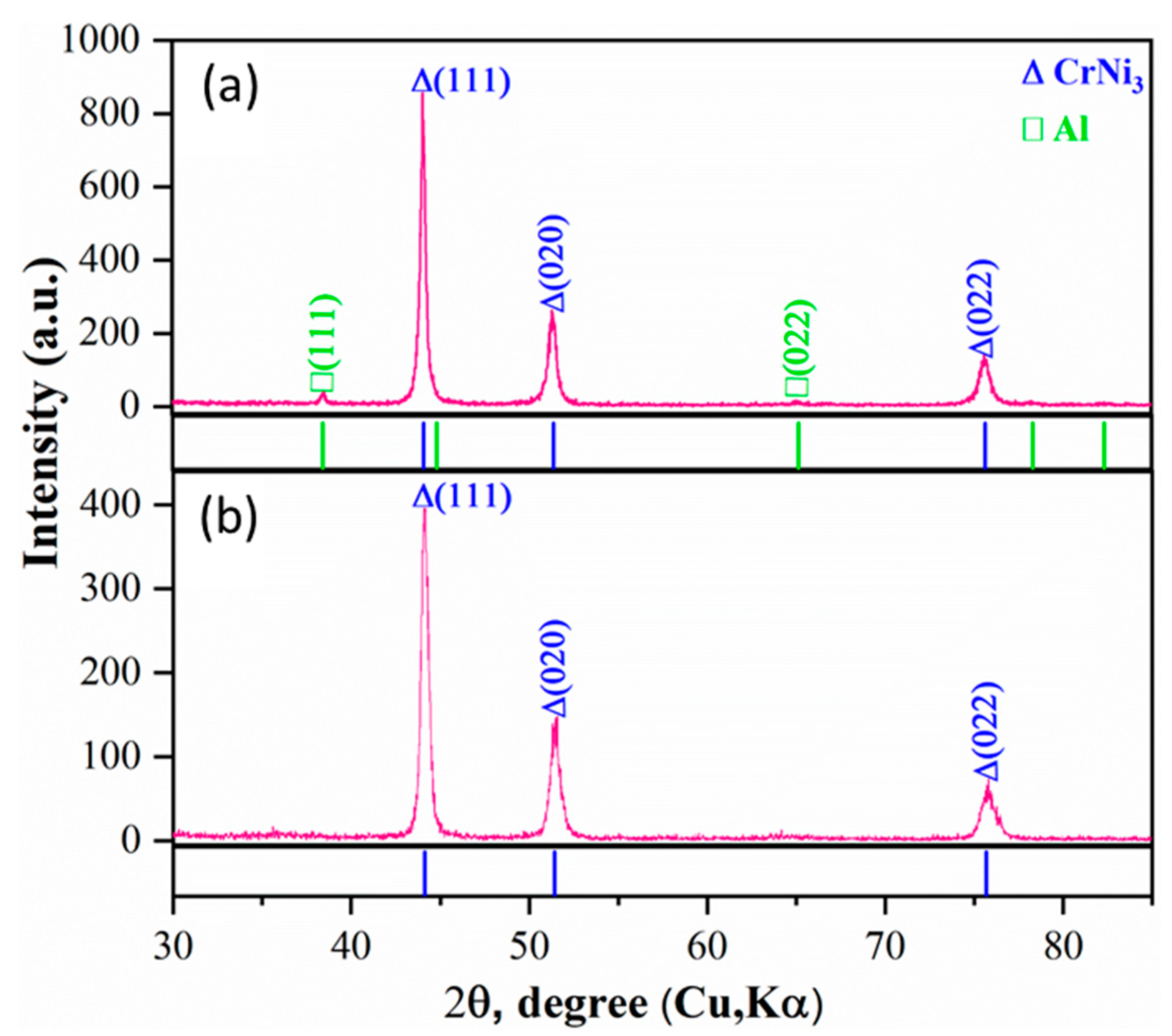
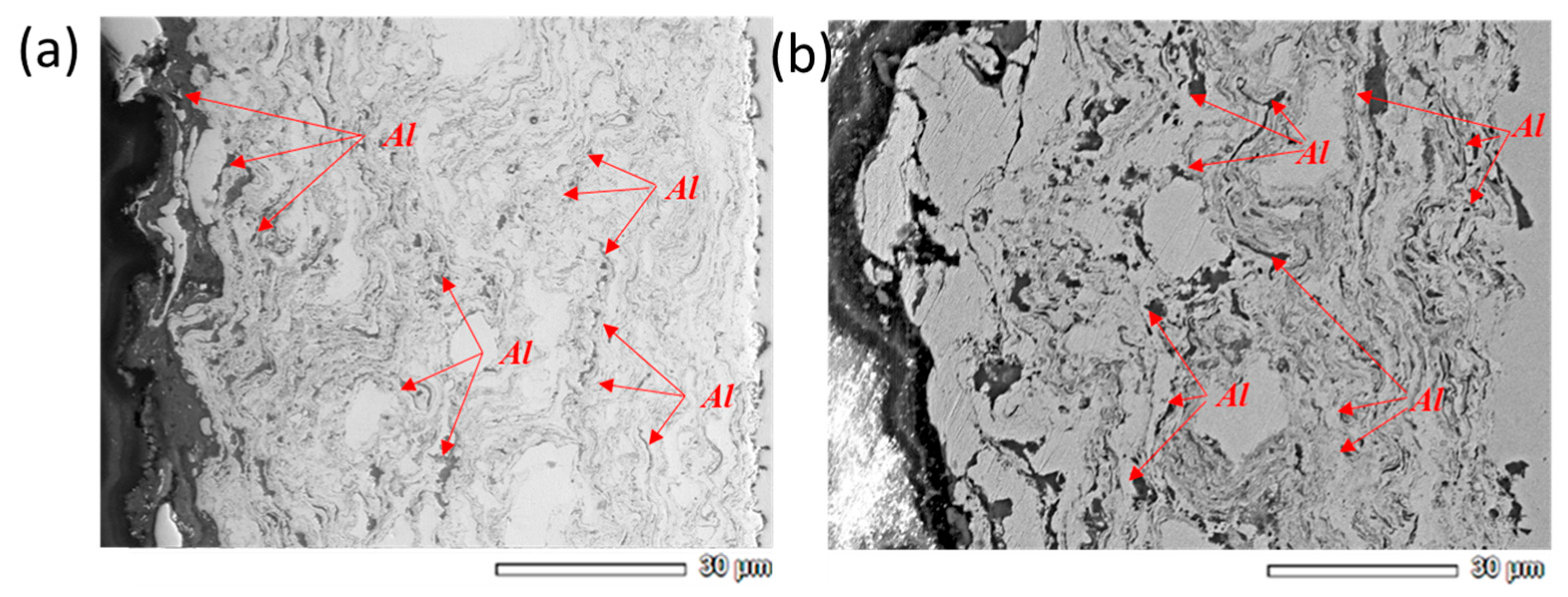
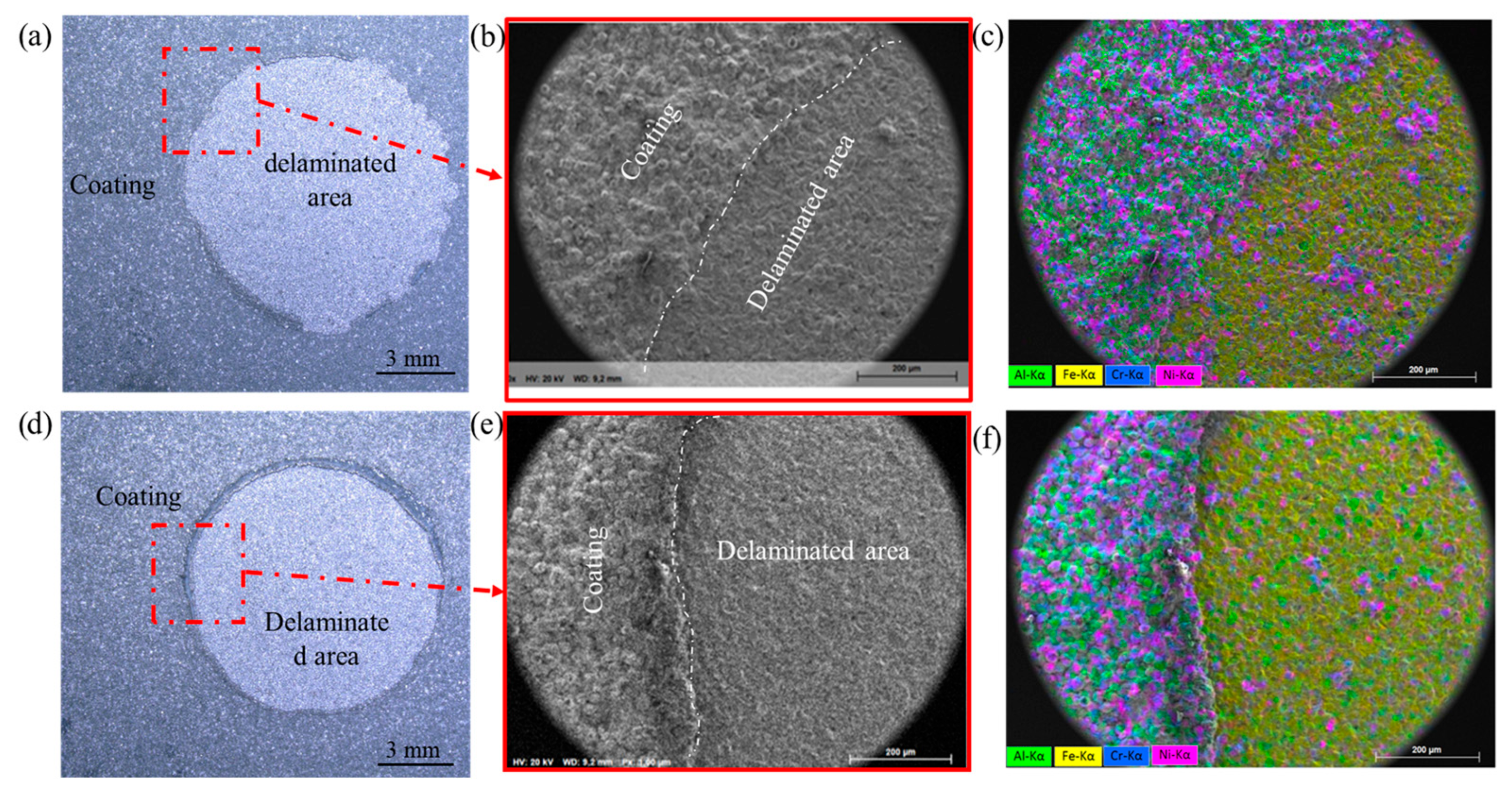
3.1. Microstructure and Phase Analysis

Figure 6 presents the results of X-ray phase analysis of homogeneous (HC) and gradient (GC) structured NiCr-Al coatings obtained by the detonation spraying (DS) method. The HC coating consists primarily of the CrNi3 phase, and no Al phases were detected due to the high-temperature conditions of the spraying process. In contrast, the GC sample contains both CrNi3 and Al phases. The formation of the Al phase is attributed to the reduction in the filling volume of the explosive gas mixture in the detonation barrel during the coating process [41]. This demonstrates that the phase composition of the coating structure obtained by the DS method can be flexibly controlled by adjusting the spraying parameters. These results differ significantly from coatings obtained by plasma spraying techniques such as atmospheric plasma spray (APS) and high velocity oxy-fuel (HVOF). For example, Sundararajan et al. [52] reported that in two-layer NiCr/Al coatings obtained via APS, only Al phases were initially identified, while the XRD signals from the underlying NiCr layer were weak due to the overlying 20 μm Al layer. This indicates that the Al topcoat formed a continuous but non-uniform structure. In the case of NiCr-Al coatings produced by HVOF, XRD analysis revealed that nickel (γ-phase) was dominant, while the diffraction peaks for Cr and Al were relatively weak [53]. In this context, the advantage of the DS method for producing gradient NiCr-Al coatings lies in its ability to control the phase composition—particularly the formation of Al phases—by modifying the spraying parameters. This allows for targeted manipulation of the elemental distribution and phase relationships across the surface and subsurface layers of the coating.
The mechanical and tribological properties of the coating, as well as its phase composition and morphology (oxide, porous, and metallic lamellae), as seen in [54], altered the wear performance of the coating by manipulating its microstructure. Figure 7 presents the cross-sectional images of the homogeneous (HC) and gradient (GC) structures of the NiCr-Al coating. By gradually decreasing the detonation energy (from 50% to 25%), the amount of aluminum in the surface layer increased, forming a GC structure with an upward gradient in Al content from the substrate toward the coating surface. As a result, the coating exhibited a high density and low porosity (<1%) (Figure 7a). In contrast, it was found that the HC coating, obtained by filling the detonation barrel with explosive gases at 50%, contained a relatively low amount of aluminum. Consequently, the insufficient presence of molten Al between CrNi3 particles limited the formation of a dense matrix, leading to an NiCr-Al coating with relatively higher porosity (2.22%) (Figure 7b). These results were compared with NiCr-Al coatings obtained using other spraying methods. For example, in coatings produced by the high-velocity oxy-fuel (HVOF) method, the particles are deposited onto the substrate in a semi-molten state at high velocities, forming a dense, layered structure through intense plastic deformation. Such coatings typically have low porosity levels (<1.7%), with aluminum predominantly distributed along the splat boundaries. Moreover, oxidation during HVOF spraying is limited due to the short in-flight time of the particles and the relatively low oxidizing potential of the environment [53]. In contrast, NiCr-Al coatings produced by the atmospheric plasma spray (APS) technique involve fully molten particles that impact the substrate at lower velocities. This results in coatings that are generally more porous, contain more oxides, and tend to form intermetallic phases (NiAl, Ni2Al3) as well as internal oxides (Al2O3, Cr2O3) [52]. The main advantage of the detonation spraying (DS) method lies in the ability to tailor the coating structure by adjusting the fill ratio of the detonation barrel. In GC coatings, the upward-directed distribution of aluminum enables the formation of a high-density coating with a compositional gradient.

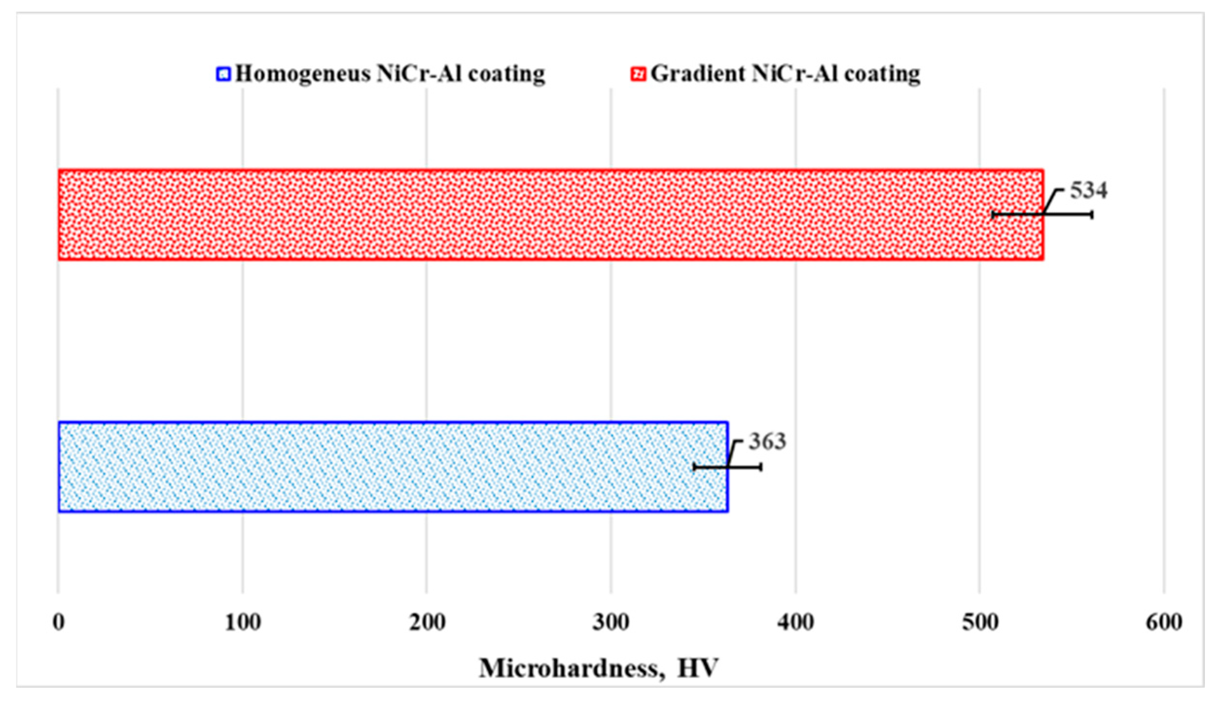
3.2. Mechanical Properties

Figure 8 presents the results of adhesion strength testing of NiCr-Al coatings. The tests were carried out by bonding the coated surface to a counterface using a high-strength epoxy-based adhesive (Epidian 53, rated at 70 MPa), followed by tensile pull-off testing (Figure 4). The fracture morphology (Figure 8a,d) indicates a predominantly adhesive failure, as confirmed by elemental analysis showing the dominance of Fe in the peeled regions (Figure 8c,f), implying that separation occurred at the coating–substrate interface. Interestingly, partial retention of coating elements in the GC sample (Figure 8c) suggests stronger interfacial bonding in the gradient structure. Quantitative results showed that the average adhesion strength of the gradient coating (GC) was 38.7 ± 6.9 MPa, whereas that of the homogeneous coating (HC) was 25.4 ± 3.1 MPa. This demonstrates a significant enhancement in adhesion due to the gradient structure, which may be attributed to the gradual variation in aluminum content, contributing to better stress distribution and interfacial compatibility. When compared to literature data, HVOF-sprayed NiCr-Al coatings typically exhibit higher adhesion strength, often in the range of 50–60 MPa, depending on substrate preparation and process parameters. For example, Mahesh et al. reported a bond strength of approximately 59 MPa for HVOF-sprayed NiCr-Al coatings on superalloy substrates [53]. This is likely due to the extremely high particle velocities and intense plastic deformation during HVOF deposition, which promote mechanical interlocking and metallurgical bonding at the interface. In contrast, the lower adhesion strength observed in the current detonation-sprayed (DS) coatings may be related to the cyclic nature of the detonation wave. Nevertheless, the adhesion performance of the GC coating remains notable, especially when compared to conventional homogeneous structures.
The results of measuring the microhardness of NiCr-Al HC and GC using the Vickers method are shown in Figure 9. The microhardness of the GC of NiCr-Al coating is approximately 30% higher compared to the HC. It can be concluded that the difference in the microhardness of the NiCr-Al coating is related to its microstructure. The porosity of the HC based on element distribution is higher compared to the GC NiCr-Al (Figure 7).
Figure 10 shows the values of nanohardness (H, GPa) and elastic modulus (E, GPa) along the cross-section of different structured NiCr-Al coatings based on element distribution. The distribution of nanohardness and elastic modulus values of NiCr-Al coating shown in Figure 10a corresponds to the gradient structure based on element distribution. The microstructure of the cross-section of the NiCr-Al coating, as shown in Figure 7a, reveals that due to the high amount of Al in the surface region, the values of hardness and elastic modulus are low, while they increase towards the substrate due to the higher presence of the CrNi3 phase. Additionally, the elastic modulus and hardness of the substrate are lower compared to the coating. According to reference data, the elastic modulus of the 12Kh1MF steel used as the substrate is approximately 198 GPa, and its hardness is between 2.8 and 3.0 GPa. Figure 10b shows the results of the study of the HC NiCr-Al based on element distribution. The elastic modulus and hardness are approximately two times lower compared to the GC based on element distribution. These results are consistent with the microhardness values determined using the Vickers method (Figure 9). The porosity of the HC based on element distribution is higher compared to the NiCr-Al GC (Figure 7b). That is, the low values of the elastic modulus and hardness of the HC NiCr-Al are related to its higher porosity. Additionally, the values of the coating’s elastic modulus and hardness are uniformly distributed across the coating thickness.

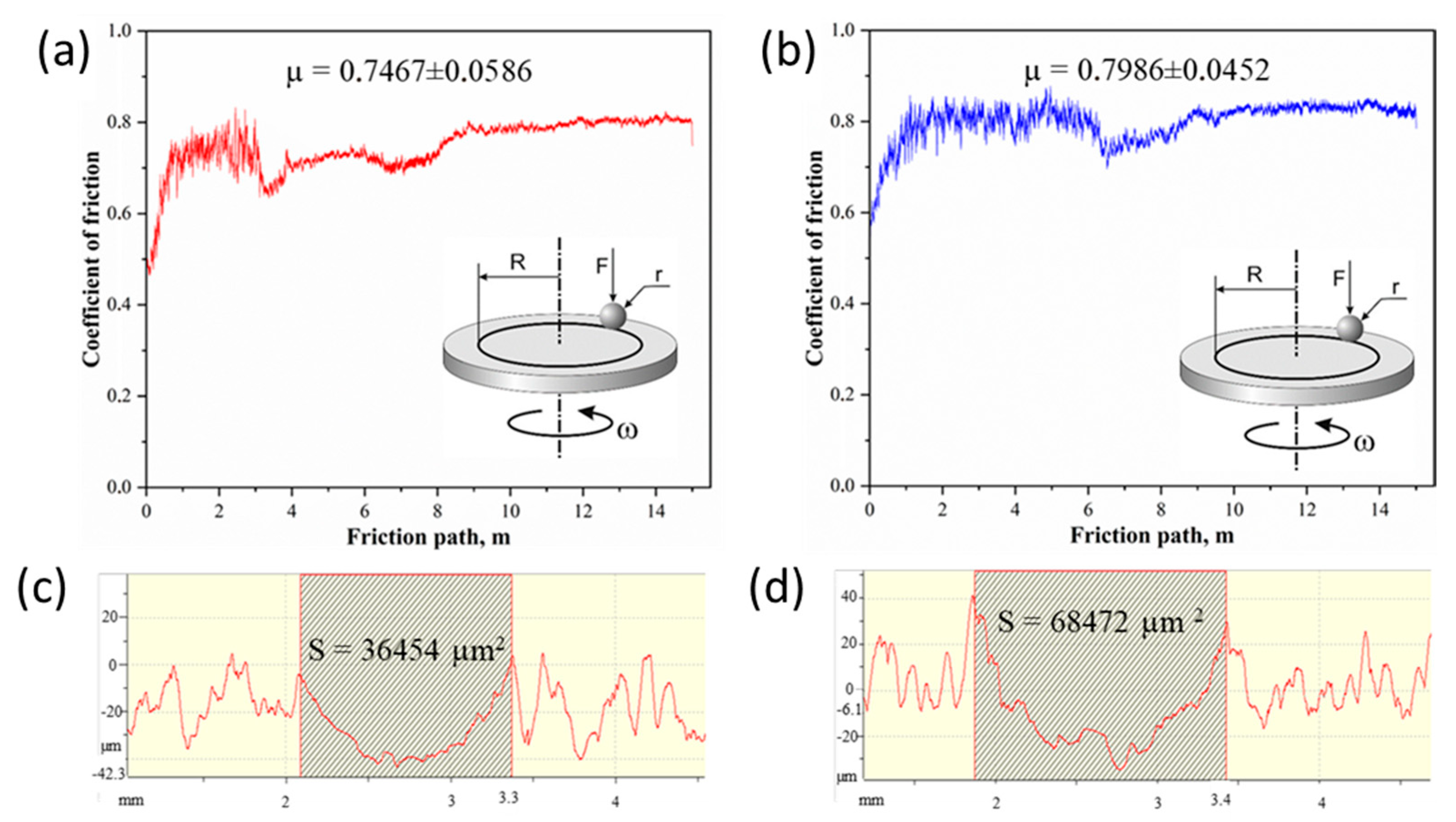
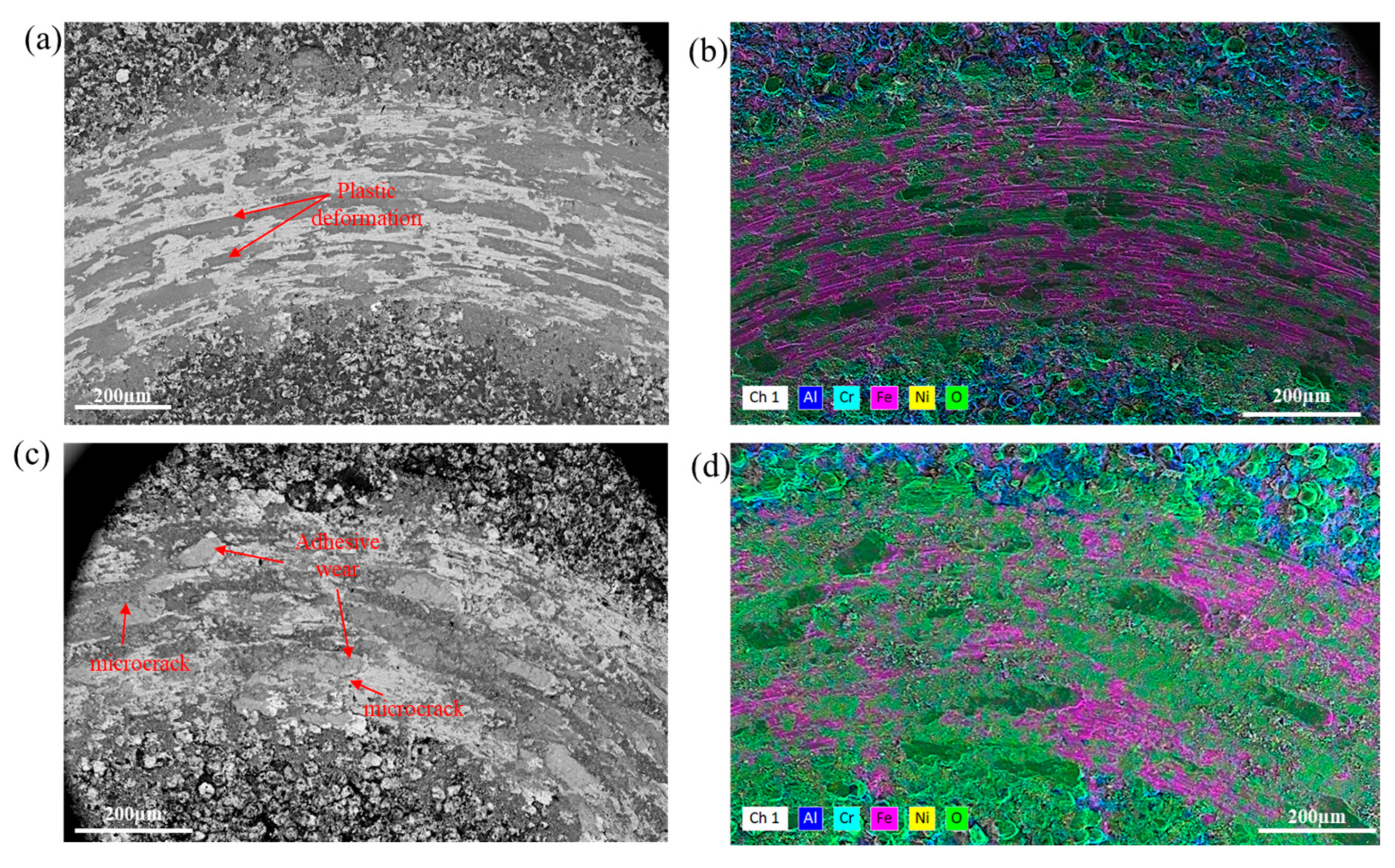
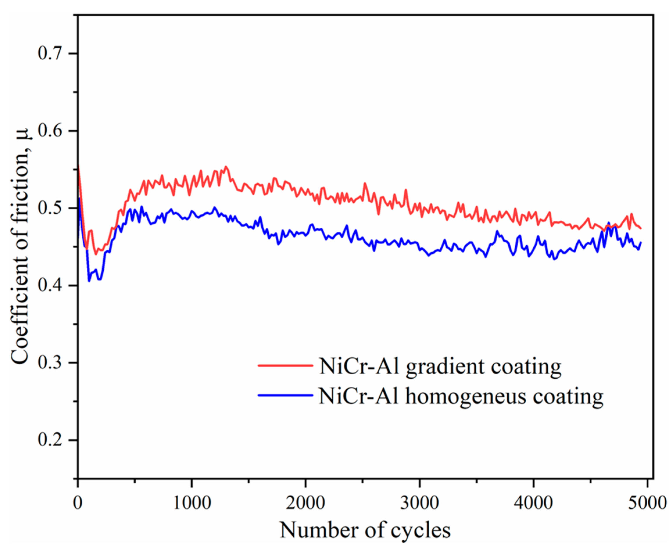
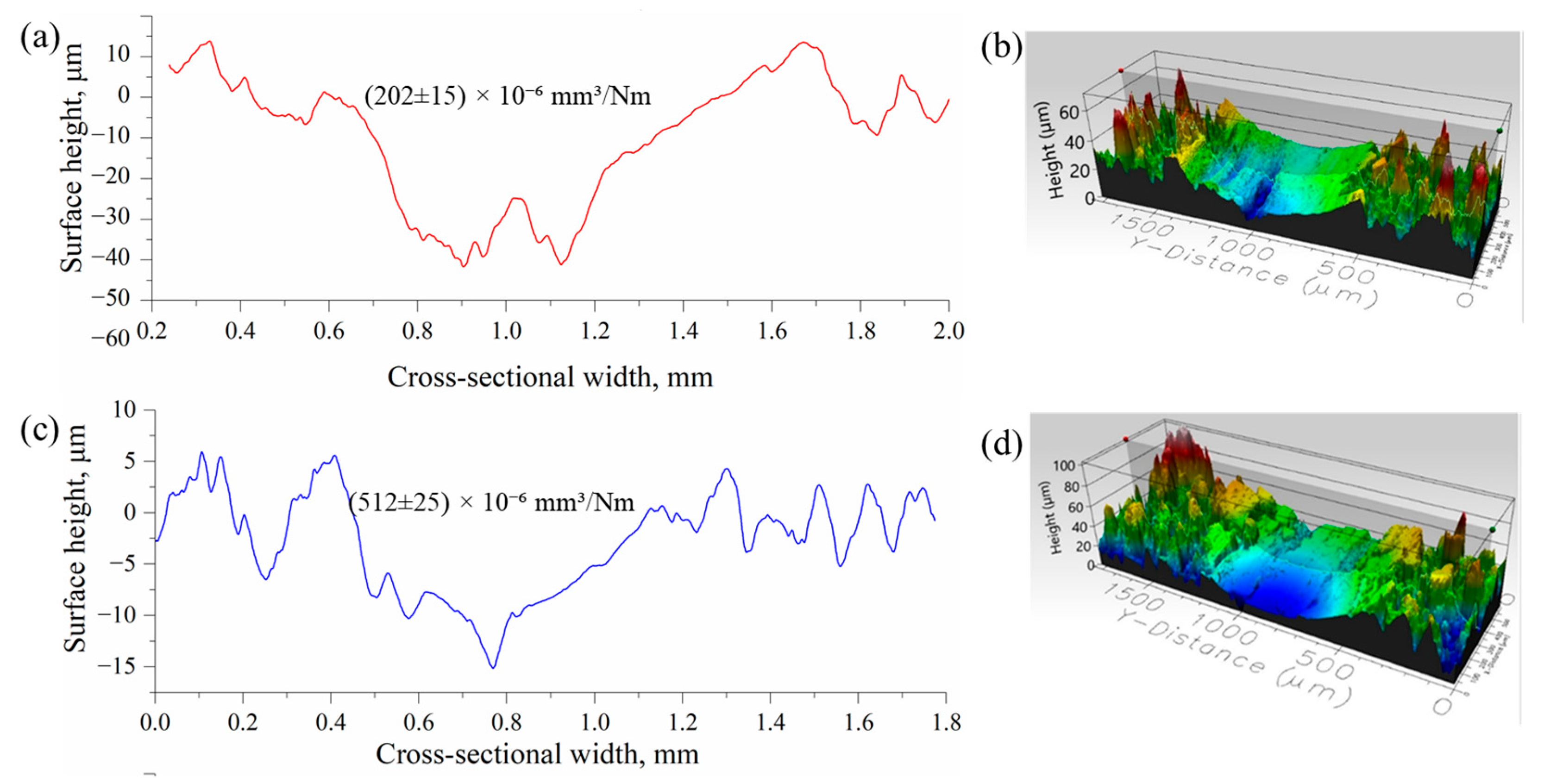
3.3. Wear Characteristics

The tribological properties of GC and HC NiCr-Al based on element distribution were determined by the friction coefficient (µ) and wear rate (Wυ, mm3/N × m) (Figure 11). Figure 11a shows the results of tribological testing of the GC NiCr-Al. The graph shows that initially the friction coefficient varied somewhat, and then it reached a relatively stable level. This could be attributed to the gradient structural characteristics of the coating. The friction test results between the NiCr-Al GC and 100Cr6 steel are as follows: µ = 0.74 ± 0.05; Wυ = (3.13 ± 0.20) × 10−3 mm3/N × m. Figure 11b shows the results of tribological testing of the HC: µ = 0.80 ± 0.04; Wυ = (5.73 ± 0.30) × 10−3 mm3/N × m. Figure 11c,d show the wear track profiles after tribological testing, and the wear area of the HC is two times higher compared to the GC. Thus, the results of tribological testing of the GC and HC using the “ball-on-disk” method, based on element distribution, reveal that the GC has higher wear resistance.
Figure 12 shows the SEM images of the wear tracks of the NiCr-Al detonation-sprayed coatings after tribological testing. In the GC coating (Figure 12a), due to the high aluminum content in the surface layer (as shown in Figure 7a), the material demonstrates enhanced plasticity, which reduces the likelihood of brittle fracture. As a result, the GC coating surface undergoes more extensive plastic deformation under frictional load. In contrast, the HC coating (Figure 12b) exhibits visible microcracks and fragmentation, indicating a higher tendency for brittle failure. Based on elemental analysis and SEM observations, the dominant wear mechanism appears to be adhesive in nature. This finding corresponds well with the observations made by Vaz et al. [55], where adhesive wear was reported in CGS 316L stainless steel coatings. In that study, plastically deformed debris adhered to the wear track and contributed to the third-body wear mechanism. Although both coatings exhibited similar coefficients of friction, profilometric measurements (Figure 11c,d) revealed that the wear area of the HC coating was approximately twice as large as that of the GC coating. This difference can be attributed to the fragmentation and detachment of coating particles from the HC structure as a result of crack formation during tribological loading. In contrast, the GC structure, with its gradient distribution of aluminum and higher structural integrity, demonstrates superior resistance to wear.
The high-temperature tribological properties of GC and HC NiCr-Al were determined by the friction coefficient (µ) and wear rate (Wυ, mm3/N × m) (Figure 13). The results of the average friction coefficient after high-temperature tribological testing using the “ball-on-disk” method for NiCr-Al coatings are as follows: GC µave= 0.50 ± 0.03; HC µave = 0.46 ± 0.02. The slightly higher friction coefficient of the GC NiCr-Al can be explained by the higher amount of aluminum on the coating surface, which leads to the formation of a thicker Al2O3 oxide layer. This oxide layer then interacts with the Al2O3 ball used as the counterbody, resulting in friction between the two hard bodies.
Figure 14a,b show the two-dimensional and three-dimensional profiles of the GC NiCr-Al after the high-temperature tribological testing. The average wear volume of the coating is Wvt = (202 ± 15) × 10−6 mm3/Nm. The three-dimensional profile shows that the wear track is deep and narrow, and additionally, high micro-scratches are retained in the peripheral areas of the coating surface, indicating abrasive wear of the coating. Figure 14c,d show the results of the study of the HC NiCr-Al. The average wear volume of the coating is Wvt = (512 ± 25) × 10−6 mm3/Nm, which is twice as high compared to the GC. The HC shows adhesive wear, with the wear track being wider and shallower (15 µm) and distributed across the entire surface, which indicates that the material has been pulled off and locally damaged, compared to the GC. The three-dimensional profile (Figure 14c) shows smoothed or flat grooves in the worn area, indicating that micro-layers have been pulled off as a result of adhesion.
The comparative presentation of the results obtained during the study of the mechanical and tribological properties of NiCr-Al detonation coatings is provided in Table 2.

4. Conclusions

A comprehensive comparison of homogeneous and gradient-structured NiCr-Al detonation coatings has shown that gradient coatings exhibit superior mechanical and tribological performance. These improvements are attributed to favorable microstructural features, such as gradual elemental distribution and enhanced phase homogeneity, which contribute to increased hardness, adhesion strength, and wear resistance. The findings suggest that gradient NiCr-Al coatings are promising candidates for protective applications in high-temperature and high-load environments, including energy, aerospace, and heavy machinery sectors. Future research may focus on the optimization of gradient structures and assessment of their performance under complex service conditions such as corrosion, erosion, and thermal cycling.

Author Contributions

Conceptualization, Z.S. and L.S.; methodology, M.M.; software, S.B.; validation, C.D., Z.S. and L.S.; formal analysis, M.M.; investigation, M.M.; resources, C.D.; data curation, Z.S.; writing—original draft preparation, M.M.; writing—review and editing, B.R.; visualization, Z.S.; supervision, L.S.; project administration, M.M.; funding acquisition, Z.S. All authors have read and agreed to the published version of the manuscript.

Funding

This research has been funded by the Science Committee of the Ministry of Science and Higher Education of the Republic of Kazakhstan (Grant No. AP23490355).

Institutional Review Board Statement

Not applicable.

Informed Consent Statement

Not applicable.

Data Availability Statement

The original contributions presented in the study are included in this article; further inquiries can be directed to the corresponding author.

Conflicts of Interest

Author Bauyrzhan Rakhadilov was employed by the company PlasmaScience LLP. The remaining authors declare that the research was conducted in the absence of any commercial or financial relationships that could be construed as a potential conflict of interest.

References

  1. Seraffon, M.; Simms, N.J.; Sumner, J.; Nicholls, J.R. Oxidation Behaviour of NiCrAl and NiCoCrAl Bond Coatings Under Industrial Gas Turbine Conditions. Oxid. Met. 2013, 81, 203–215. [Google Scholar] [CrossRef]
  2. Seraffon, M.; Simms, N.J.; Sumner, J.; Nicholls, J.R. The Development of New Bond Coat Compositions for Thermal Barrier Coating Systems Operating Under Industrial Gas Turbine Conditions. Surf. Coat. Technol. 2011, 206, 1529–1537. [Google Scholar] [CrossRef]
  3. Xie, Y.; Wang, M.; Zhang, G.; Chang, M. Analysis of Superalloy Turbine Blade Tip Cracking During Service. Eng. Fail. Anal. 2006, 13, 1429–1436. [Google Scholar] [CrossRef]
  4. Poblano-Salas, C.A.; Cabral-Miramontes, J.A.; Gallegos-Melgar, A.; Ruiz-Luna, H.; Aguilar-Escobar, J.D.; Espinosa Arbelaez, D.G.; Espinoza-Beltran, F.; Trapaga Martinez, G.; Munoz-Saldana, J. Effects of VC additions on the mechanical properties of bimodal WC-Co HVOF thermal sprayed coatings measured by nanoindentation. Int. J. Refract. Met. Hard Mater. 2015, 48, 167–178. [Google Scholar] [CrossRef]
  5. Cabral-Miramontes, J.A.; Gaona-Tiburcio, C.; Almeraya-Calderon, F.; Estupinan-Lopez, F.H.; Pedraza-Basulto, G.K.; Poblano-Salas, C.A. Parameter Studies on High-Velocity Oxy-Fuel Spraying of CoNiCrAlY Coatings Used in the Aeronautical Industry. Int. J. Corros. 2014, 2014, 703806. [Google Scholar] [CrossRef]
  6. Gaona-Tiburcio, C.; Aguilar, L.M.R.; Zambrano Robledo, P.; Estupinan Lopez, F.; Cabral Miramontes, J.A.; Nieves-Mendoza, D.; Castillo-Gonzalez, E.; Almeraya-Calderon, F. Electrochemical Noise Analysis of Nickel Based Superalloys in Acid Solutions. Int. J. Electrochem. Sci. 2014, 9, 523–533. [Google Scholar] [CrossRef]
  7. Liang, G.Y.; Su, J.Y. The Microstructure and Tribological Characteristics of Laser-Clad Ni–Cr–Al Coatings on Aluminium Alloy. Mater. Sci. Eng. A 2000, 290, 207–212. [Google Scholar] [CrossRef]
  8. Yang, X.; Zhou, Y.; Zhao, M.; Liu, P.; Qi, H.; Yang, Y. Impact of Al Nanoparticles upon the Microstructure and Wear Properties of Ni-Cr-Al Nanocomposite Coatings. J. Indian Chem. Soc. 2023, 100, 100822. [Google Scholar] [CrossRef]
  9. Zhao, X.; Dong, T.; Fu, B.; Li, G.; Liu, Q.; Li, Y. Microstructure and Properties of Cold Sprayed NiCrAl Coating on AZ91D Magnesium Alloy. Coatings 2023, 11, 193. [Google Scholar] [CrossRef]
  10. Zhen, H.; Peng, X. A New Approach to Manufacture Oxidation-Resistant NiCrAl Overlay Coatings by Electrodeposition. Corros. Sci. 2019, 150, 121–126. [Google Scholar] [CrossRef]
  11. Peng, X.; Zhen, H.; Tian, L.; Wang, X.; Wang, K.; Xie, Y. A Novel Strategy to Apply Metallic Nanoparticles to Manufacture NiCrAl Composite Coatings Smartly Growing Chromia and Alumina. Compos. Part B Eng. 2022, 234, 109721. [Google Scholar] [CrossRef]
  12. Zhen, H.; Xie, Y.; Tian, L.; Peng, X. Discontinuous Oxidation in Wet Air of T91 with a Novel Al2O3-Forming NiCrAl Nanocomposite Coating in As-Deposited and Pre-Oxidized States. Surf. Coat. Technol. 2022, 449, 128937. [Google Scholar] [CrossRef]
  13. Mahesh, R.A.; Jayaganthan, R.; Prakash, S. Evaluation of Hot Corrosion Behaviour of HVOF Sprayed NiCrAl Coating on Superalloys at 900 °C. Mater. Chem. Phys. 2008, 111, 524–533. [Google Scholar] [CrossRef]
  14. Mahesh, R.A.; Rengaswamy, J.; Prakash, S. High Temperature Oxidation Studies on HVOF Sprayed NiCrAl Coatings on Superalloys. Surf. Eng. 2011, 27, 332–339. [Google Scholar] [CrossRef]
  15. Mahesh, R.A.; Rengaswamy, J.; Prakash, S. Evaluation of Hot Corrosion Behaviour of HVOF Sprayed Ni–5Al and NiCrAl Coatings in Coal Fired Boiler Environment. Surf. Eng. 2010, 26, 413–421. [Google Scholar] [CrossRef]
  16. Aristu, D.; Carlos, B.-L.; Alberro, M.; Rández, X.; Fernández, A.G. A Comprehensive Study on Hot Corrosion Resistance of NiCoCrAlYTa and NiCrAl Thermal-Sprayed Coatings for CSP Applications. J. Energy Storage 2023, 74, 109346. [Google Scholar] [CrossRef]
  17. Celik, E.; Ozdemir, I.; Avci, E.; Tsunekawa, Y. Corrosion Behaviour of Plasma Sprayed Coatings. Surf. Coat. Technol. 2005, 193, 297–302. [Google Scholar] [CrossRef]
  18. Stathopoulos, V.; Sadykov, V.; Pavlova, S.; Bespalko, Y.; Fedorova, Y.; Bobrova, L.; Salanov, A.; Ishchenko, A.; Stoyanovsky, V.; Larina, T.; et al. Design of Functionally Graded Multilayer Thermal Barrier Coatings for Gas Turbine Application. Surf. Coat. Technol. 2016, 295, 20–28. [Google Scholar] [CrossRef]
  19. Ghadami, F.; Sabor Rouh Aghdam, A.; Ghadami, S. Microstructural Characteristics and Oxidation Behavior of the Modified MCrAlX Coatings: A Critical Review. Vacuum 2021, 185, 109980. [Google Scholar] [CrossRef]
  20. Sathish, M.; Radhika, N.; Saleh, B. A Critical Review on Functionally Graded Coatings: Methods, Properties, and Challenges. Compos. Part B Eng. 2021, 225, 109278. [Google Scholar] [CrossRef]
  21. Latka, L.; Pawlowski, L.; Winnicki, M.; Sokolowski, P.; Malachowska, A.; Kozerski, S. Review of Functionally Graded Thermal Sprayed Coatings. Appl. Sci. 2020, 10, 5153. [Google Scholar] [CrossRef]
  22. Fethi, R.; Wei, H.; Saleh, B.; Radhika, N.; Jiang, J.; Ma, A.; Ahmed, M.H.; Li, Q.; Ostrikov, K.K. Past and Present of Functionally Graded Coatings: Advancements and Future Challenges. Appl. Mater. Today 2022, 26, 101373. [Google Scholar] [CrossRef]
  23. Kumar, A.; Patnaik, P.C.; Chen, K. Damage Assessment and Fracture Resistance of Functionally Graded Advanced Thermal Barrier Coating Systems: Experimental and Analytical Modeling Approach. Coatings 2020, 10, 474. [Google Scholar] [CrossRef]
  24. EL-Galy, I.M.; Bassiouny, B.I.; Ahmed, M.H. Empirical Model for Dry Sliding Wear Behavior of Centrifugally Cast Functionally Graded Composite Based on Pure Al/SiCp. IOP Conf. Ser. Mater. Sci. Eng. 2018, 786, 276–285. [Google Scholar] [CrossRef]
  25. Su, Y.; Chen, B.; Tan, C.; Song, X.; Feng, J. Influence of Composition Gradient Variation on the Microstructure and Mechanical Properties of 316L/Inconel718 Functionally Graded Material Fabricated by Laser Additive Manufacturing. J. Mater. Process. Technol. 2020, 283, 116702. [Google Scholar] [CrossRef]
  26. Uysal, M.U. Numerical Modeling of Functional Graded TiB Coating in Nanoindentation on Determination of Mechanical Properties. Mater. Today Proc. 2015, 2, 217–223. [Google Scholar] [CrossRef]
  27. Saleh, B.; Ahmed, M. Wear Characteristics of Functionally Graded Tubes Reinforced with Silicon Carbide and Alumina: A Comparative Study. Trans. Nanjing Univ. Aeronaut. Astronaut. 2021, 38, 76–83. [Google Scholar]
  28. Lv, B.; Fan, X.; Li, D.; Wang, T.J. Towards Enhanced Sintering Resistance: Air-Plasma-Sprayed Thermal Barrier Coating System with Porosity Gradient. J. Eur. Ceram. Soc. 2018, 38, 1946–1956. [Google Scholar] [CrossRef]
  29. Vaßen, R.; Rauwald, K.H.; Guillon, O.; Aktaa, J.; Weber, T.; Back, H.C.; Qu, D.; Gibmeier, J. Vacuum Plasma Spraying of Functionally Graded Tungsten/EUROFER97 Coatings for Fusion Applications. Fusion Eng. Des. 2018, 133, 148–156. [Google Scholar] [CrossRef]
  30. Kumar, S.; Reddy, K.; Kumar, A.; Devi, G. Development and Characterization of Polymer–Ceramic Continuous Fiber Reinforced Functionally Graded Composites for Aerospace Application. Aerosp. Sci. Technol. 2013, 26, 185–191. [Google Scholar] [CrossRef]
  31. Pasupuleti, K.T.; Dsouza, S.; Thejaraju, R.; Venkataraman, S.; Ramaswamy, P.; Murty, N. Performance and Steady State Heat Transfer Analysis of Functionally Graded Thermal Barrier Coatings Systems. Mater. Today Proc. 2018, 5, 27936–27945. [Google Scholar] [CrossRef]
  32. Yuan, S.; Lin, N.; Zou, J.; Lin, X.; Liu, Z.; Yu, Y.; Wang, Z.; Zeng, Q.; Chen, W.; Tian, L.; et al. In-Situ Fabrication of Gradient Titanium Oxide Ceramic Coating on Laser Surface Textured Ti6Al4V Alloy with Improved Mechanical Property and Wear Performance. Vacuum 2020, 176, 109327. [Google Scholar] [CrossRef]
  33. Kim, J.H.; Kim, M.C.; Park, C.G. Evaluation of Functionally Graded Thermal Barrier Coatings Fabricated by Detonation Gun Spray Technique. Surf. Coat. Technol. 2003, 168, 275–280. [Google Scholar] [CrossRef]
  34. Kumar, R.R.; Maruno, S. Functionally Graded Coatings of HA-G-Ti Composites and Their In Vivo Studies. Mater. Sci. Eng. A 2002, 334, 156–162. [Google Scholar] [CrossRef]
  35. Anil Kumar, R.; Radhika, N. Enhancement of Mechanical and Wear Properties of Tungsten Carbide Coated AA 6063 Alloy Using Detonation Gun Technique. Trans. Inst. Met. Finish. 2018, 96, 212–219. [Google Scholar] [CrossRef]
  36. Rakhadilov, B.; Buitkenov, D.; Sagdoldina, Z.; Idrisheva, Z.; Zhamanbayeva, M.; Kakimzhanov, D. Preparation and Characterization of NiCr/NiCr-Al2O3/Al2O3 Multilayer Gradient Coatings by Gas Detonation Spraying. Coatings 2021, 11, 1524. [Google Scholar] [CrossRef]
  37. Rakhadilov, B.; Kakimzhanov, D.N.; Buitkenov, D.B.; Kozhanova, R.S.; Zhurerova, L.G.; Sagdoldina, Z.B. Tribological and Mechanical Properties of Gradient Coating on Al2O3-Based Coating Produced by Detonation Spraying Methods. Hindawi Adv. Tribol. 2023, 2023, 1520135. [Google Scholar] [CrossRef]
  38. Kakimzhanov, D.; Rakhadilov, B.; Sulyubayeva, L.; Dautbekov, M. Influence of Pulse-Plasma Treatment Distance on Structure and Properties of Cr3C2-NiCr-Based Detonation Coatings. Coatings 2023, 13, 1824. [Google Scholar] [CrossRef]
  39. Buitkenov, D.; Nabioldina, A.; Raisov, N. Development of Method for Applying Multilayer Gradient Thermal Protective Coatings Using Detonation Spraying. Coatings 2024, 14, 899. [Google Scholar] [CrossRef]
  40. Buitkenov, D.; Rakhadilov, B.K.; Nabioldina, A.; Mukazhanov, Y.; Adilkanova, M.; Raisov, N. Investigation of Structural Phase, Mechanical, and Tribological Characteristics of Layer Gradient Heat-Protective Coatings Obtained by the Detonation Spraying Method. Materials 2024, 17, 5253. [Google Scholar] [CrossRef]
  41. Rakhadilov, B.; Maulet, M.; Abilev, M.; Sagdoldina, Z.; Kozhanova, R. Structure and Tribological Properties of Ni-Cr-Al Based Gradient Coating Prepared by Detonation Spraying. Coatings 2021, 11, 218. [Google Scholar] [CrossRef]
  42. Rakhadilov, B.; Sagdoldina, Z.; Maulet, M.; Buitkenov, D.; Sulubayeva, L. Method of Obtaining Functionally Gradient Coating. Patent for Utility Model. No. 8922, Republic of Kazakhstan, 7 March 2024. [Google Scholar]
  43. Rakhadilov, B.; Sulyubayeva, L.; Maulet, M.; Sagdoldina, Z.; Buitkenov, D.; Issova, A. Investigation of High-Temperature Oxidation of Homogeneous and Gradient Ni-Cr-Al Coatings Obtained by Detonation Spraying. Coatings 2024, 14, 11. [Google Scholar] [CrossRef]
  44. ISO 4955; Heat-Resistant Steels. International Organization for Standardization (ISO): Geneva, Switzerland, 2016.
  45. Nikolaev, Y.A.; Vasiliev, A.A.; Ulianitsky, V.Y. Gas detonation and its application in engineering and technologies (Review). Combust. Explos. Shock Waves 2003, 39, 382–410. [Google Scholar] [CrossRef]
  46. ISO 14916; Thermal Spraying — Determination of Tensile Adhesive Strength. International Organization for Standardization (ISO): Geneva, Switzerland, 2017.
  47. GOST R ISO 6507-1-2007; Metallic Materials — Vickers Hardness Test — Part 1: Test Method. Standartinform (Federal Agency on Technical Regulating and Metrology): Moscow, Russia, 2008.
  48. GOST R 8.748-2011; State System for Ensuring the Uniformity of Measurements. Metallic Materials. Instrumented Indentation Test for Hardness and Materials Parameters. Part 1: Test Method. Standartinform (Federal Agency for Technical Regulation and Metrology): Moscow, Russia, 2013.
  49. ASTM G 99; Standard Test Method for Wear and Friction Testing with a Pin-on-Disk or Ball-on-Disk Apparatus. ASTM International: West Conshohocken, PA, USA, 2023.
  50. ISO 20808:2016; Fine Ceramics (Advanced Ceramics, Advanced Technical Ceramics) — Determination of Friction and Wear Characteristics of Monolithic Ceramics by Ball-on-Disc Method. International Organization for Standardization (ISO): Geneva, Switzerland, 2016.
  51. ISO 13565-1:1996; Geometrical Product Specifications (GPS) — Surface Texture: Profile Method — Surfaces Having Stratified Functional Properties — Part 1: Filtering and General Measurement Conditions. International Organization for Standardization (ISO): Geneva, Switzerland, 1996.
  52. Sundararajan, T.; Kuroda, S.; Abe, F. Steam oxidation resistance of two-layered Ni–Cr and Al APS coating for USC boiler applications. Corros. Sci. 2005, 47, 1129–1147. [Google Scholar] [CrossRef]
  53. Makesh, R.A.; Jayaganthan, R.; Prakash, S. Microstructural characteristics and mechanical properties of HVOFsprayed NiCrAl coating on superalloys. J. Alloys Compd. 2009, 468, 392–405. [Google Scholar]
  54. Vaz, R.F.; Sucharski, G.B.; Chicoski, A.; Siqueira, I.B.; Tristante, R.; Pukasiewicz, A.G. Comparison of FeMnCrSi Cavitation Resistance Coatings Deposited by Twin-Wire Electric Arc and High-Velocity Oxy-Fuel Processes. J. Therm. Spray Technololgy 2021, 30, 754–771. [Google Scholar] [CrossRef]
  55. Vaz, R.F.; Silvello, A.; Sanchez, J.; Albaladejo, V.; Cano, I.G. The Influence of the Powder Characteristics on 316L Stainless Steel Coatings Sprayed by Cold Gas Spray. Coatings 2021, 11, 168. [Google Scholar] [CrossRef]
Figure 1. Morphology (a) and particle size distribution (b) of the NiCr-Al (20%) composite powder.
Applsci 15 07513 g001
Figure 2. CCDS2000 detonation spraying system.
Applsci 15 07513 g002
Figure 3. Schematic diagram of the coating deposition process using the CCDS2000 detonation system [45]. 1—control computer; 2—gas distributor, 3—mixing and ignition chamber, 4—igniter, 5—inlet valve, 6—fuel line, 7—oxygen line, 8—gas valves, 9—gas supply unit, 10—barrel bore section, 11—powder feeder (dispenser), 12—workpiece; 13—manipulator, 14—barrel muzzle section.
Applsci 15 07513 g003
Figure 4. Adhesion strength testing schematic.
Applsci 15 07513 g004
Figure 5. Schematic representation of tribological tests conducted using the “Ball-on-disk” method: (a) TRB3 tribometer; (b) high-temperature T-21 tribometer.
Applsci 15 07513 g005
Figure 6. Results of X-ray phase structural analysis of gradient (a) and homogeneous (b) NiCr-Al coatings.
Applsci 15 07513 g006
Figure 7. Microstructure of the cross-section of NiCr-Al detonation coatings. (a) Gradient; (b) Homogeneous.
Applsci 15 07513 g007
Figure 8. Gradient (ac) and homogeneous (df) structured NiCr-Al coatings after adhesion strength testing: (a,d) surface images of the samples; (b,e) morphology of the coating and peeled areas; (c,f) results of elemental analysis.
Applsci 15 07513 g008
Figure 9. Microhardness of NiCr-Al coatings obtained by the detonation spraying method.
Applsci 15 07513 g009
Figure 10. Nanohardness and elastic modulus of NiCr-Al coatings with gradient (a) and homogeneous (b) structure of element distribution.
Applsci 15 07513 g010
Figure 11. Results of tribological testing and wear volume of gradient (a,c) and homogeneous (b,d) NiCr-Al coatings obtained by the detonation spraying method.
Applsci 15 07513 g011
Figure 12. Morphology of the wear tracks of NiCr-Al (20%) coatings after tribological testing. (a,b) Gradient; (c,d) Homogeneous.
Applsci 15 07513 g012
Figure 13. The results of high-temperature tribological tests of NiCr-Al coatings obtained by the detonation spraying method.
Applsci 15 07513 g013
Figure 14. Two-dimensional (a,c) and three-dimensional (b,d) profiles of the wear tracks of homogeneous (a,b) and gradient (c,d) NiCr-Al coatings after high-temperature tribological testing.
Applsci 15 07513 g014
Table 1. Deposition parameters for HC and GC NiCr-Al produced by the detonation spraying method.
Coating StructureO2/C2H2Spraying Distance, mmBarrel Filling Volume, %Number of Shots
Homogeneous 1.8561505040
Gradient1.8561505010
4010
3010
2510
Table 2. Correlation table of the obtained results.
Coating StructurePhase CompositionAdhesion, MPaMicrohardness, HVTribometer TRB3Tribometer T-21
µWv, mm3/N × mµmm3/N × m
HomogeneousCrNi325.4 ± 3.1363 ± 100.80 ± 0.04(5.73 ± 0.30) × 10−30.50 ± 0.03(512 ± 25) × 10−6
GradientCrNi3, Al38.7 ± 6.9534 ± 120.74 ± 0.05(3.13 ± 0.20) × 10−30.46 ± 0.02(202 ± 15) × 10−6
Disclaimer/Publisher’s Note: The statements, opinions and data contained in all publications are solely those of the individual author(s) and contributor(s) and not of MDPI and/or the editor(s). MDPI and/or the editor(s) disclaim responsibility for any injury to people or property resulting from any ideas, methods, instructions or products referred to in the content.

