1. Introduction
Numerous international studies have been conducted on plasma reactors (PRs) and electrostatic precipitators (ESPs), both of which utilise the corona phenomenon. Their operation is based on the application of a medium voltage (DC or pulse voltage, tens of kV) between the discharge and collection electrodes to obtain the corona effect [
1,
2,
3,
4,
5,
6,
7,
8].
Many studies on plasma reactors refer to the reduction of volatile organic compounds, CO
2, NO, and NO
x concentrations performed under laboratory conditions (laboratory models) used for various applications, such as diesel engines, kitchens, or in strict laboratory conditions [
1,
2,
3,
4]. There are studies on ESP used for low-power boilers (kW of thermal power) and some ESPs used for low-power boilers that have small ionisation zones, with direct implications for operation [
5,
6,
8,
9,
10,
11,
12]. Most research on ESPs has been conducted using small laboratory models [
13,
14,
15,
16,
17].
When burning wood on stoves, comparative studies were carried out with separate or combined operations with ESP (with DC medium-voltage) and platinum/palladium catalysts [
18,
19]. The use of a larger number of collector tubes leads to a slight increase in collection efficiency, but maintenance is much more difficult [
20]. Some studies have been conducted on the use of cylindrical-type ESPs (CESPs) with several tubes mounted in cylindrical or rectangular enclosures between the boiler and chimney [
21,
22,
23,
24]. It has been found that ESPs with one section have a simple design because they are supplied from a single DC medium voltage (usually up to 30 kV). Different configurations (simpler or more complex) of electrical insulators have been used and experimented under the conditions under which they work in difficult conditions (high temperature and humidity, dirty gases), because their resistance decreases with time, and the voltage applied between the electrodes is lower (the Corona is less intense) [
19,
20,
25].
Research was conducted on the placement of medium-voltage insulators. By placing the medium-voltage insulators outside the gas flow (oblique to the vertical chimney or near the chimney), a decrease in the rapid deposition of dirt on the surface of the medium-voltage insulators was observed. The disadvantages of these methods include the use of small discharge electrodes (reduced corona effect), major deficiencies in the centring of the discharge electrode in the collection electrode (the applied voltage is lower and the corona is much reduced), and small dust collection (30–40%) [
18,
25].
The smoke resulting from wood combustion consists of particulate matter (PM), NO
x, CO, CO
2, formaldehyde, volatile organic compounds, CH
4, H
2, and so on. Smoke from burning wood is composed of a complex mixture of gases and fine particles (PM 10, PM 2.5, PM 1) [
5,
7,
26,
27,
28,
29]. These components are harmful to human health, as to well as the environment [
30,
31].
PRESPs can encounter several problems during operation, such as the cleaning of medium-voltage insulators and collector electrodes, re-entrainment of particles from collector electrodes, and long-term stability of medium-voltage insulators [
5,
7,
9,
10,
11]. Some problems occur when moisture is condensed in the gas on the surface of the insulators, and short currents occur [
5,
6,
8,
19,
20,
25].
This article presents an analysis of medium-voltage electric insulators for a cylindrical-type plasma reactor and electrostatic precipitator made directly in the chimney (stainless steel). In this way, the PRESP footprint on the ground is missing, which solves a real problem.
This article analyses the modification of the electrical properties of the medium-voltage insulators used at PRESP and does not focus on the performance of the plasma reactor and the collection of the cylindrical-type electrostatic precipitator. The article has the following structure: introduction, materials and method, results, discussions, and the last section, conclusions.
2. Materials and Method
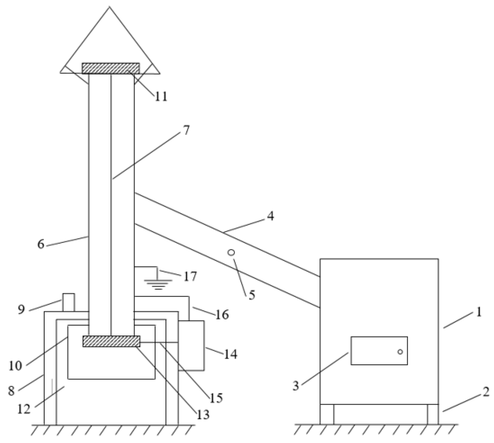
The experiments were conducted using a low-power boiler 1 that burned wood with a thermal power of 20 kW (
Figure 1). The boiler has support 2 and the wood supply door 3. The boiler smoke outlet had an outer diameter of 125 mm. A connection tube (stainless steel tube) 4 (1.45 m long) between chimney 6 (stainless steel tube, PRESP) and boiler 3 has an access area 5 for measuring the smoke and gases after the boiler. The chimney has a height of 4.5 m, an inner diameter of 125 mm, and an outer diameter of 129 mm. Inside the chimney is a thin wire (discharge electrode, with a constant cross-section) 7 with a diameter of 0.75 mm, stretched on the central axis of the chimney through an electrical medium-voltage insulator 11 in the upper part of the chimney and an electrical medium-voltage insulator 13 in the lower part. The discharge electrode 7 is stretched, and there is a weight at the bottom. A metal conical cover is placed at the upper end of the chimney to prevent water from entering the chimney during rain. The chimney is supported by the support with legs 8, on which is an electromagnet 9 used for shaking, a collection device 10, a medium-voltage source 14 with conductor 15 supplying the discharge electrode 7 (negative polarity of the medium-voltage source), and conductor 16 (positive polarity of the medium-voltage source; it is also connected to the ground) that connects to the chimney 6 (the collection electrode).
Chimney 6 is connected by two bridges, and metallic support 8 is connected by one bridge to an earth socket consisting of four electrodes inserted into the ground. The electric resistance is 3.5 Ω (must be less than 4 Ω; measured with 8PK-ST1520, Pro’sKit (Hsinchu, Taiwan)—device for measuring the earth socket with a resolution of 0.1 Ω).
PRESP can work in combination using two electrodes (one discharge electrode and another collection electrode, by applying a DC medium-voltage): a plasma reactor, with the possibility of reducing chemical compounds (CO, NOx), and an electrostatic precipitator to reduce the concentration of dust (PM) at the output of the chimney.
During the operation of the PRESP, dirt is deposited on the medium-voltage electrical insulators. The electrical properties of medium-voltage electrical insulators are influenced by dust and gases resulting from combustion.
To analyse the PRESP, it is compared with other CESP. Some characteristics of the domestic CESP connected to low-power boilers are as follows: radius of the collection tube r = 8 cm; active length of the precipitator L = 0.5 m; number of collection tubes n = 6; lateral surface for a tube S
l = 0.19 m
2; total lateral surface: S
lt = 1.13 m
2; diameter of the discharge electrode with constant cross-section Φc = 1 mm; switching voltage source with medium voltage up to 30 kV, DC; and can be connected to a boiler with a maximum power of 50 kW [
23].
The main features of the PRESP (
Figure 1) connected to a 20 kW boiler are as follows:
- -
Radius of the collection stainless steel tube: r = 62.5 mm (diameter D = 125 mm);
- -
Active length of the precipitator: h = 4.5 m;
- -
The number of collection tubes: n = 1;
- -
Discharge electrode diameter (with a constant cross-section): Φc = 0.75 mm;
- -
The maximum DC medium-voltage power supply (with short-circuit protection, max. 10 mA): U = 30 kV.
The gas flow at the input of the domestic precipitator is Q = 40–65 m
3/h (0.0111–0.018 m
3/s) [
5,
6,
9,
13,
23,
28]. The cross-section of the cylindrical precipitator is:
St = 0.012272 m2.
The average speed in the cross-section of the domestic precipitator can be computed as follows:
For Q = 40 m
3/h, v
avg = 0.904 m/s was obtained, and for Q = 65 m
3/h, v
avg = 1.469 m/s was obtained. The average time spent by the particles in the electric field was calculated as follows:
After calculation, for Q = 40 m3/h, tavg = 4.978 s, and for Q = 65 m3/h, 3.063 s are obtained.
A lower gas flow rate ensures a longer gas passage time near the discharge electrode, which ensures better treatment of gases and dust collection. The time (approximately) to electrostatic charge of small particles (<1 μm) is [
7]:
- -
through an electric field of 0.1 s (in 90% of the cases);
- -
through diffusion 2.3 ÷ 5 s.
A lower gas velocity results in better loading of dust particles and a long enough time for the plasma reactor to operate. The average electric strength in a cylindrical-type domestic electrostatic precipitator can be calculated as [
32]:
where U is the supply voltage, and r is the radius of the cylinder.
For U = 10 kV, Eavg = 1.6 kV/cm, and U = 30 kV, Eavg = 4.8 kV/cm. Taking into account the distance between the electrodes, the maximum voltage is 30 kV.
During many experiments (conducted over 4 years), it was found that the upper-side insulator was the most demanding (due to the high temperatures above 250 °C and the gas content affecting the medium-voltage electrical insulators supporting the discharge electrode) from a thermal, mechanical, and, in particular, electrical point of view (
Figure 2 and
Figure 3).
In
Figure 2: 1—the stainless steel tube of the chimney; 2—the upper metal cover from the top part of the chimney; 3—metal supports for attaching the metal upper cover to the tube of the chimney; 4—metal collar for fastening on the chimney tube; 5—the upper-side electrical insulator, type 1, with dimmensions of 250 × 60 × 20 mm, mounted in the top part to connect the discharge electrode; 6—discharge electrode; 7—metallic terminal element for supporting the discharge electrode on the upper-side electrical insulator; 8—ceramic support mounted in the lower part of the chimney for centring the discharge electrode; 9—textolite electro-insulating support (lower side electrical insulator) for supporting and centring the discharge electrode; 10—weight for stretching the discharge electrode; 11—the negative potential of the medium-voltage source mounted at the discharge electrode; 12—the positive potential of the medium-voltage source mounted on the stainless steel chimney (collecting electrode); 13—grounding the chimney (through an earth socket).
The purpose of the upper and lower side electrical insulators that support the discharge electrode connected to the medium-voltage source is to ensure a high electrical resistance between the discharge electrode and the chimney (which is the collecting electrode) under conditions of dust, chemical compounds, humidity, and high temperature.
Over time, two types (type 1 and type 2) of upper-side electrical insulators have been tested: a simpler rectangular porcelain insulator with a metal rain protection cover (5, type 1,
Figure 2; ensures a small distance between two electrodes, equal to D/2) and a more complex one with porcelain insulators and a porcelain cover (2, 5, type 2,
Figure 3; ensures a much greater distance, more than 2.5 times compared to type 1,
Figure 2).
The material used for the medium-voltage insulators was porcelain, which has very good properties as an electrical insulator at high temperatures, humidity, and under dirty conditions (dust deposits). Electrical insulation on the lower side is much less stressed: temperatures below 100 °C
, and it is not directly in the gas flow; instead, the dust falling on the insulator can change its properties). The electrical insulator supporting and centring the discharge electrode consists of a ceramic support (8) and a cylindrical textile support (9), as shown in
Figure 2.
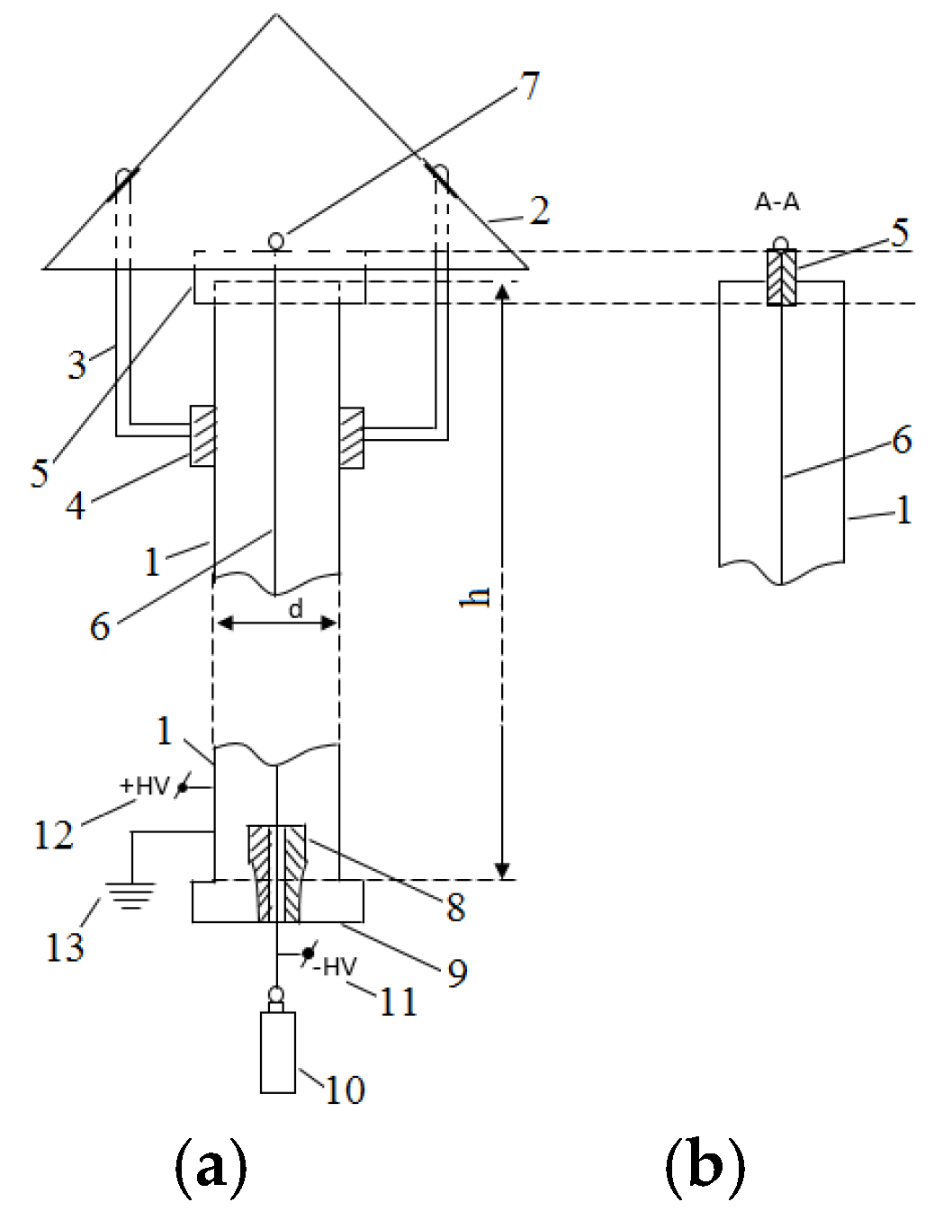
In
Figure 3a, there are three electrical insulators (5) offset by 120°. In
Figure 3: 1—the stainless steel tube of the chimney; 2—the upper porcelain cover from the top part of the chimney (diameter 240 mm; height 110 mm); 3—metal supports to connect the components; 4—cylindrical collars to attach metal supports to the chimney; 5—3 × 18 kV medium-voltage porcelain electrical insulator (three elements connected in series); 6—discharge electrode; 7—metallic terminal element to support the discharge electrode on the upper porcelain cover; 8—electrical insulation against moisture with 40 mm diameter; 9—metal supports to hold the upper ceramic cover; 10—component mounting holes. Medium-voltage insulators (5,
Figure 3) are three insulators connected in series (to operate at a higher voltage); a simple insulator has the following characteristics: voltage 18 kV, outer diameter 40 mm, four striations (striation thickness 5 mm, distance between two successive striations 5 mm), height 40 mm, and mechanical connection M8. For configuration type 2, (5,
Figure 3), three medium-voltage insulators connected in series (3 × 18 kV) are distributed in three arms.
3. Results
To exemplify the concentration of some compounds during the combustion of wood, O
2, NO, NO
2, NO
x, CO
2, CO, and H
2 were measured with the TESTO 350XL analyser (Lenzkirch, Germany) (specialised analyser for measuring combustion gases according to sensors on chemical compounds; sensors were used for detection O
2, NO, NO
2, NO
x, CO
2, CO, and H
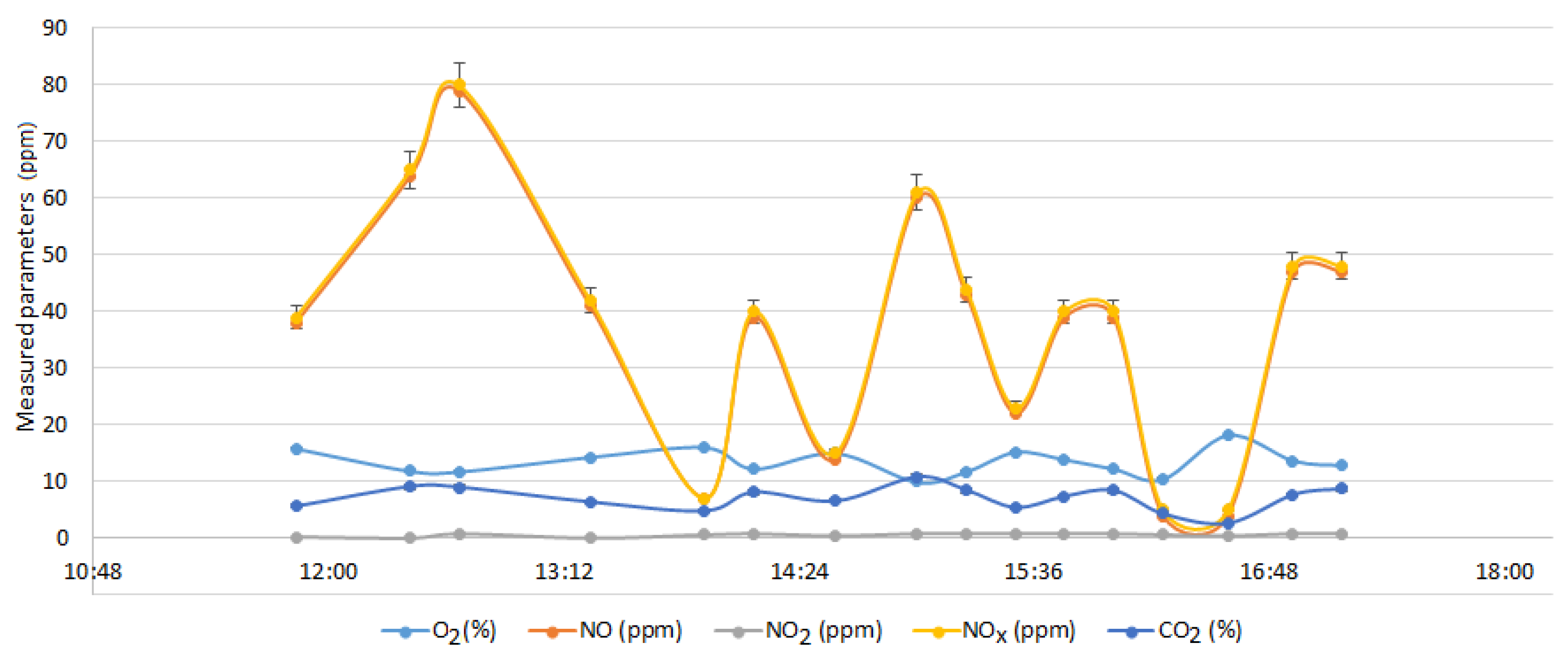
2; also, measure the ambient air temperature and gas temperatures) without using the medium-voltage source to supply PRESP (
Figure 4). The measurements were performed at the exit of the chimney. At the same time, the gas temperature at the chimney output and the ambient temperature were measured (
Figure 5). Dry wood (less than 10% humidity) was burned in the stove (about 2.3–2.8 kg per load, from time to time).
In
Figure 4 and
Figure 5, the error bars for the measured values have been passed. For O
2 and CO
2 (
Figure 4), the errors are below 0.8%, and for the temperature (
Figure 5), the errors are below 1% (for this reason, the error bars are not visible on the graphs).
During the supply of wood to the boiler, NO and NOx increase to high values (at the beginning of the operation to 80 ppm, after a few hours to 40–60 ppm), as well as the temperature of the gases at the output of the chimney. After a period of operation (2–3 h), the operating temperature decreases, as do the concentrations of NO and NOx. During the beginning of wood burning, the concentration of O2 decreases and CO2 increases, and after the wood has burned, the evolution is reversed for O2 and CO2.
Other quantities were also measured: CO, which had values above 5000 ppm (the device can measure up to 5000 ppm; lower values after burning the wood 3500–4500 ppm; in this stage, evaluations were also made on the operation of the plasma reactor); and H2, which had values above 2000 ppm (the device can measure up to 2000 ppm; lower values after burning the wood 1000–1700 ppm).
The metallic chimney, together with the central electrode, forms a cylindrical capacitor, whose electrical capacitance is calculated as [
32]
After performing the calculations using the PRESP data, C = 48.867 pF. The measured electrical capacitance (consisting of the stainless steel chimney and the central discharge electrode) with air (εr = 1), when the boiler is not working, is 50 pF. During boiler operation (with smoke at high temperatures and humidity), as the temperature increases, the electrical capacitance increases (εr > 1): 67 pF at 198 °C, 68 pF at 202 °C, and 71 pF at 244 °C.
Some factors in computing and evaluating insulation quality are the dielectric absorption ratio (D
ar) and the polarisation index (P
i) [
32].
The values of D
ar and P
i are used to estimate the quality of the electric insulation (in principle, values above unity indicate better quality of insulation). This is achieved by plotting the insulation resistance with respect to time and calculating the D
ar and P
i values. For a medium-quality insulation material, the resistance should increase when a measuring voltage is applied [
32].
When measuring the electrical parameters that characterise the electrical insulators of PRESP (5, 8, 9
Figure 2; 2, 3
Figure 3), the UNILAP ISO 5kV megohmmeter (test voltages up to 5 kV) and LEM were used, which can apply DC test voltages of 0.5, 1, 2.5, and 5 kV.
Table 1 shows the experimental measurements (before and after cleaning; R
iso—isolation resistance) on the lower side of the electrical insulator (9,
Figure 2a), which must be cleaned periodically. The experiments were carried out for three hours during which a fire was started in the boiler with dry wood (humidity < 10%).
For type 1 upper-side electrical insulator (5,
Figure 2), measurements were performed before using the gas flow from the boiler. The measurements are presented in
Table 2 and
Table 3, where the insulation resistances are very high (of the order of GΩ when the electrical insulator is clean) and decrease after it has been used.
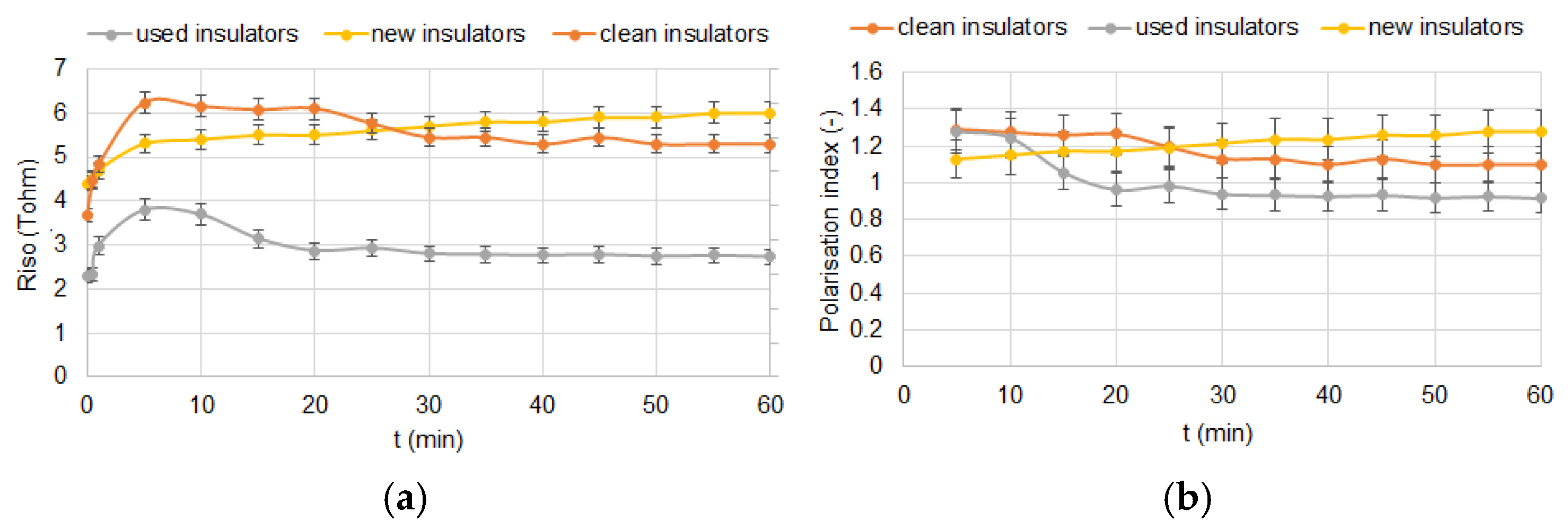
For the upper-side type 2 configuration (5, 9,
Figure 3a), three groups of single insulators connected in series were used for safety in operation and to increase the operation. As shown in
Figure 6, experiments were carried out on insulators connected in series (3 × 18 kV). Each graph was created for a time of 60 min. Error bars have been added to the graphs.
For the upper type 2 electrical insulator with the configuration shown in
Figure 3a. The insulation resistance and dielectric absorption ratio were measured at different test voltages (1 kV and 2.5 kV), and the results are listed in
Table 4.
For the chemical analysis of dust, measurements were made with a spectrometer (sequential X-ray fluorescence spectrometer, Thermo Scientific ARL X900 XRF spectrometer, UniQuant Software, Thermo Fischer, Waltham, MA, USA) on the dust deposited on the electro-insulating supports of the chimney [
33,
34]. The results are presented in
Appendix A Table A1,
Table A2 and
Table A3. The chemical compounds deposited on the electrical insulators determine the modification of the electrical properties (especially the insulation resistance) of the electrical insulators (the most sensitive are the upper-side medium-voltage insulators, type 2,
Figure 3) for PRESP. The surface electrical resistance between the metal ends of the electrical insulators (5, 9,
Figure 3) changes.
4. Discussions
The lower side insulator must be cleaned often (at least every 2 days) because the insulation resistance drops significantly (to tens of MΩ). In the future, the lower side insulator should be replaced with a porcelain insulator (it has better dielectric qualities and can work at high temperatures). After cleaning, the resistance of the lower side insulator increasesby tens of times (when testing with 2.5 or 5 kV).
The design of medium-voltage electrical insulators is crucial, particularly for the high reliability and optimal operation of the PRESP. A longer length of the electrical isolation route (longer length in type 2,
Figure 3, compared to type 1,
Figure 2) ensures better operation (possibility of applying a higher average voltage over long periods of time because the insulation resistance has high values).
The use of the three support arms of the upper-side medium-voltage insulator (porcelain) cover (2,
Figure 3) leads to a reduction in the insulation resistance. In future research, another two-arm clamping system should be designed. The explanation is as follows: by using three identical electrical resistances connected in parallel (R
iso/3), the equivalent electrical resistance is lower than that obtained by using two electrical resistances connected in parallel (R
iso/2). The insulation resistance values of the insulation resistances are high (>2 TΩ) for the configuration with three insulators connected in series (
Figure 6). It was observed that the insulation resistance increases with time, which indicates a good quality.
In the configuration with three insulators connected in series (
Figure 6), the insulation resistance is high (over 4.3 TΩ) over time. If the insulators have been used for a period of time, it is observed that the insulation resistance drops to almost half (compared to the situation when they were clean), and the evolution of the resistance is no longer increasing (which indicates that the electrical properties of the insulation are affected). After cleaning the electrical insulators, the electric resistance increases by 0.5–0.7 TΩ, but the evolution over time decreases. The same evolutions can be found in the polarisation index: for clean insulators, the evolution of the polarisation index is increasing (values above 1.1), and in the other two situations, the evolutions of the polarisation index are decreasing.
Carbon (which is in high concentration in the layer deposited on the insulators over 23%;
Appendix A Table A1,
Table A2 and
Table A3) has a low electrical resistivity. For some chemical elements and compounds (K
2O, CaO, Cl, Fe
2O
3, and ZnO), the electrical resistivity decreases with increasing temperature. All these elements or chemical compounds that were found in high concentrations in the electrical insulators (relative mass greater than 2.7%,
Appendix A Table A1,
Table A2 and
Table A3) change the insulation resistance of the electrical insulators. Some chemical compounds can create acids that directly act on PRESP elements.
In order not to decrease the insulation resistance, the following measures can be taken:
- -
The use of wood as dry as possible (humidity below 10%), preferably hardwood;
- -
Avoid frequent start-ups of the boiler, the performance of the PRESP being greatly reduced during the start-up of the boiler, which can last 1.5–2 h, and when wood is introduced into the boiler;
- -
Boiler operation at the nominal regime for as long periods of time as possible;
- -
The use of electrical insulation with as large isolation routes as possible;
- -
Periodic cleaning of the electrical insulator from deposits that change the insulation resistance;
- -
Periodic replacement of the discharge electrode because, at some point, it can break and put the PRESP out of action;
- -
During the operation of PRESP, the insulation resistance of electrical insulators can decrease by 10 times compared to the situation when they are new;
- -
By cleaning electrical insulators, the insulation resistance increases, but not to the initial values (when the insulator is new);
- -
To indicate the quality of the electrical insulator, the polarisation index is more useful (values above 1.1–1.2 are for good quality of the insulation) compared to the dielectric absorption ratio (which can have high values, 1.3–1.5 when the insulator is dirty).
In the following, a cost analysis is made of implementing a PRESP under the conditions in which the investments in the boiler, the stainless steel chimney, and the stainless steel have been made:
- -
medium-voltage switched mode power supply (max. 30 kV, DC) with overcurrent protection (max. 10 mA) and short circuit: Euro 250;
- -
medium-voltage insulator from the upper-side of the chimney (type 2,
Figure 3): Euro 200;
- -
medium-voltage insulator from the lower side of the chimney (
Figure 2): Euro 50;
- -
earth socket (for connecting the chimney) consisting of galvanised stakes, galvanised connection plate, and copper conductor: Euro 125.


