Abstract
To enhance the speed control performance of the permanent magnet synchronous motor (PMSM) servo system, an improved sliding mode control method integrating a torque observer is presented. The current loop uses current feedback decoupling PID control, and the speed loop applies sliding mode control. In comparison to previous work in hybrid SMC using fuzzy logic and torque observers, this p proposes a hyperbolic tangent function in replacement of the signum function to solve the conflict between rapidity and chattering in the traditional exponential reaching law, and fuzzy and segmental self-tuning rules adjust relevant switching terms to reduce chattering and improve the sliding mode arrival process. A load torque observer is designed to enhance the system’s anti-interference ability by compensating the observed load torque to the current loop input. Simulation results show that compared with traditional sliding mode control with a load torque observer (SMC + LO), PID control with a load torque observer (PID + LO), and Active Disturbance Rejection Control (ADRC), the proposed strategy can track the desired speed in 0.032 s, has a dynamic deceleration of 2.7 r/min during sudden load increases, and has a recovery time of 0.011 s, while the others have relatively inferior performance. Finally, the model experiment is carried out, and the results of the experiment are basically consistent with the simulation results. Simulation and experimental results confirm the superiority of the proposed control strategy in improving the system’s comprehensive performance.
1. Introduction
The permanent magnet synchronous motor is a hot research topic in academia and a mainstream drive motor in industry [1] and is widely used in machine tools, robots, industrial automation, and electric vehicles. Due to its multivariate, nonlinear, and strongly coupled characteristics, it is difficult to obtain high performance requirements of speed or position for the control strategy that depends on the exact mode of the system. To solve the high performance control problem of PMSM, many advanced control methods have been applied to PMSM [2], such as optimal control [3,4], model predictive control [5,6], etc. Sliding mode control is widely used in many control systems because it does not depend on the mathematical model of the plant and its robustness. However, there is high-frequency chattering in sliding mode control, which leads to the degradation of the system’s transient performance. The root cause of this problem is related to the symmetry of the switching of the system’s control variables. In [7], the state of the system is introduced to form the variable exponential power law, which reduces chattering and accelerates the state approaching speed, but the design process and the parameter adjustment are all complex. In [8], an approach law is designed by using fractional integral symbolic function to reduce chattering and increase response speed, but there is a steady-state error. In [9], a fast power law with a variable exponent is proposed to decrease chattering phenomenon. However, more parameters have to be adjusted. In [10], a chattering-free finite-time approximation law with input constraints is designed, and unfortunately its rapidity is limited. In [11], the paper proposes a fuzzy sliding mode switching controller based on adaptive law, which approximates the switching term of sliding mode control law by fuzzy algorithm to reduce system chattering. In [12], in order to ensure global robustness and reduce chattering, a full-range fractional-order integral sliding mode surface is proposed, but the controller has many parameters. In [13], an adaptive integral sliding mode is used to reduce chattering and steady-state error, but large initial error will lead to large overshoot and long adjustment time. In [14], to reduce chattering and realize finite-time speed control, a generalized super-twisting sliding mode algorithm is proposed, but steady-state analysis is complex, and the control parameters are difficult to adjust.
In addition, the load is also one of the main reasons that affect the system performance. The common method to restrain the influence of load disturbance is to measure torque directly or indirectly and then compensate it. The direct measurement method is not only costly but also high for mechanical sensors, and the indirect measurement method is low in cost and good in reliability [15]. In [16], a Kalman filter model is established to accurately observe the load torque, but the computation is large, and the parameter tuning is difficult. In [17], a torque compensation strategy based on an extended state observer is proposed. However, prior knowledge is required to determine the nominal parameters. In [18], a model predictive control is designed to estimate the load torque, but the estimation process needs to assume that the flux linkage is constant. In [19], an adaptive robust control method based on a sliding mode control mechanism is designed to address several issues related to state errors, sensor noise, and chattering. The sliding surface of this controller is adjusted dynamically by a fuzzy technique, which is formed by two inputs and one output. However, the conflict between rapidity and buffeting in the traditional exponential approach law has not been resolved.
In the paper, an exponential approach law sliding mode controller is adopted on the basis of current feedback decoupling, and the parameters of the exponential reaching term are determined automatically online in the form of piecewise functions; the parameters of equal speed switching term are adjusted automatically online according to fuzzy rules. In order to solve the symbolic function switch discontinuity, an improved smoothing function is proposed to improve the symmetry of the control signal switching and reduce the chattering. On this basis, a simple torque observer is designed to compensate the load and improve the system immunity. Finally, the proposed control strategy in this paper is compared with SMC + LO, PID + LO, and ADRC. The simulation and experimental results show that the proposed control method can quickly reach the sliding mode surface from the initial state and make the control system with strong robustness; the chattering phenomenon is effectively improved.
The main innovations of this paper are as follows: (1) Aiming at the chattering problem of the sliding mode with the exponential reaching law, a method of segmentally tuning the parameters of the exponential approaching term and fuzzily tuning the parameters of the constant-speed approaching term is proposed, which improves the response speed and reduces the chattering. (2) In view of the jump problem of the signum function in the exponential reaching law, a function whose curve shape can be flexibly adjusted is designed. (3) A two-degree-of-freedom strategy combining a torque observer with sliding mode control is proposed to improve the tracking performance and anti-disturbance ability of the system.
2. Mathematical Model of Permanent Magnet Synchronous Motor
Assuming that the embedded PMSM is an ideal motor and the anti-potential is a sine wave, regardless of eddy currents and hysteresis losses, regardless of the parameter disturbance, the magnetic field is unsaturated [20,21], etc. The voltage Equation [9] of the permanent magnet synchronous motor under the rotating coordinate is obtained as
The electromagnetic torque Equation [21] is
The equation of motion is
where is the stator phase resistance, and are axis voltages, and are axis currents, and and are axis inductors, respectively. is the permanent magnet flux; is the rotor electrical angular velocity; is the polar logarithms, and its meaning refers to the quantitative relationship between the stator coils and the rotor magnetic poles in an electric motor; is the load torque; is the mechanical angle for the rotor, and .
3. Controller Design
The system adopts a double closed-loop structure; the outer loop is sliding mode control; the inner loop is feedback decoupling PID control. The control block diagram of the system is shown in Figure 1. This double-loop structure itself can be considered a form of symmetry in control design. The inner loop focuses on the current control, while the outer loop manages the speed control, and they work in coordination with each other to achieve the desired goals.
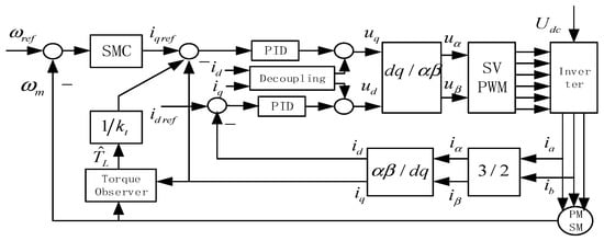
Figure 1.
System control block diagram.
3.1. Current Feedback Decoupling
According to the voltage Equation (1) under the synchronous rotation axis coordinate system, there are coupling terms and for current and velocity in the voltage equation. In addition, includes disturbance terms related to flux linkage and velocity; these cross-coupling can be offset by feedforward compensation [1,22] to realize the decoupling control, the current feedback decoupling control block diagram as shown in Figure 2.
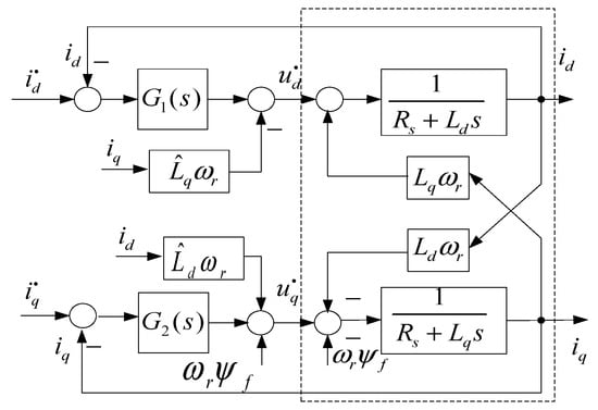
Figure 2.
Current feedback decoupling control block diagram.
With the introduction of feedback compensation, the following Equations are obtained
where and are the estimates of and ; the parameter values on the motor nameplate are selected as and ; if real-time and accurate decoupling is desired, the least-squares method and the Kalman filtering method can be used for online identification of and . and are introduced to cancel the coupling terms in the axis voltage equations of PMSM; is introduced as the compensation term of anti-potential. If , selecting , , then
From Equation (5) it can be seen that the equation is a linear equation, there is no coupling term in the voltage equation of and axis, and the control is completely decoupled, and the decoupling is a proportional link. When the control strategy is adopted, the electromagnetic torque does not include the magneto resistive torque component and is linear with the q-axis current. The process of decoupling restores a kind of symmetry to the control system. By eliminating the cross-coupling terms, it makes the control of the d and q axes more independent and symmetric, which simplifies the control process and improves the system’s control ability.
3.2. Speed Sliding Mode Controller Design
The purpose of designing the speed regulator is to make the actual speed follow the given speed quickly and accurately. The speed error and its derivative are defined as
The sliding surface of the design system is
The exponential approach law is chosen, namely
where is the constant velocity switching term, is the exponential switching term, and and are constant greater than zero. When , there is
From Equation (9), the solution of the differential equation is
From Equation (10), when is sufficiently large, the rate of convergence is faster than the exponential law [23].
When , if , there is
then
From Equation (13), it can be seen that the system can reach the sliding mode surface from the initial state in a finite time, and the parameters and all affect the time of reaching the sliding surface; increasing can improve the response speed, but too much will lead to too much speed of sliding surface. If is too small, the sliding mode surface is too slow. Small can reduce the switching chattering, while small affects the rapidity.
When the reference signal is a step signal, the following formula is available from Equation (6).
The following formula is obtained from and the Equation (8).
The expression for the control quantity is
From Equation (17), it can be seen that the chattering of the system is caused by the discontinuity of the symbolic function. The amplitude of chattering is related to , and the response speed of control variables is related to . For with poor smoothness, this paper proposes a function which not only has good smoothness but also can adjust the curve shape flexibly.
This function has the same properties as . The shape of can be changed by changing ; the slope of the output curve near the point (0, 0) can be changed by changing . The value range of can be changed by changing , that is, the maximum value when the function output is stable. When , is at 0.2 and 0.5 and 2, as shown in Figure 3; when , is at 1 and 1.5 and 2 and 2.5, as shown in Figure 4; it can be seen that has the effect of nonlinear control theory smoothness and variable in shape.
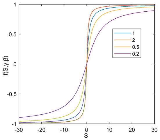
Figure 3.
characteristic curve with different value.
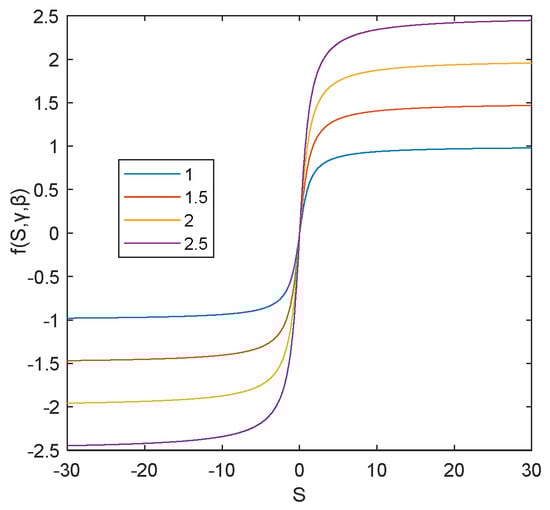
Figure 4.
characteristic curve with different value.
When S approaches 0, the approaching speed is rather than 0. is related to both the speed at which the system state point approaches the sliding surface and the amplitude of chattering when the state point slides on the sliding surface. Considering that is also one of the factors affecting system chattering, this paper proposes a fuzzy self-tuning algorithm for . The fuzzy control system takes and as inputs, and the output is . That is, , the , , and fuzzy sets are , respectively, where PB is positive big, PM is positive middle, PS is positive small, ZO is zero, NS is negative small, NM is negative middle, and NB is negative big.
The analysis shows that when the state of the system is far away from the sliding mode surface and the state track is in the approaching mode, should have a larger value. When the system state trajectory is close to the sliding mode surface, the values of should be smaller in order to reduce the chattering; the fuzzy rules formulated based on these principles are shown in Table 1.

Table 1.
Determine the fuzzy rule table for .
The domain of is chosen as [−100, 100], the domain of is chosen as [−500, 500], and the domain of is [2, 3]. MATLAB2022a software is used to calculate the fuzzy output control surface as shown in Figure 5. From the surface diagram of , the control surface is funnel-shaped. The closer both and are to the sliding mode surface, the smaller the value of .
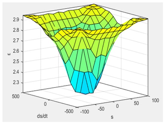
Figure 5.
The fuzzy control output control surface.
When is large, the exponential switching term can ensure that the system state point approaches the sliding mode at a relatively high speed. Therefore, the exponential reaching law is particularly suitable for solving the response control problems with step inputs. If is too large, even if the terminal error is small, the overshoot will be excessive, and the system chattering will be intensified in the steady state. If is small, the initial response will be slow. In order to consider the rapidity of the system and the maximum control force that the system can provide, segment variable control is proposed. In the initial stage of regulation, when the system error is large, should have a larger value. In the final stage of regulation, when the system error is small, should have a smaller value. Based on the absolute value of the velocity error , segmented function is determined as follows
where is the number of segments in the formula, , and . As can be seen from Table 1, although is large when the system state is far from the switching surface, the value of is even larger, thus ensuring that the transition phase still has the advantages of both small chattering and short transition time.
According to the Lyapunov stability theory, taken the energy function is , the system stability of sliding mode control should meet the following conditions, namely
From Equation (8) can be obtained; as long as and , it can be guaranteed that S and have opposite signs, satisfying the system stability condition.
3.3. Load Torque Observer Design
In a single-degree-of-freedom closed-loop control, the system has to wait for the disturbance to occur, and only when the system output changes, leading to a change in the deviation, will the output of the controller change. In this adjustment process, the suppression of the disturbance is not timely. The root cause of this problem is that a single degree of freedom cannot balance the tracking ability and the disturbance rejection ability simultaneously. For single-degree-of-freedom closed-loop control, only after the disturbance occurs and the system output changes, which in turn causes the deviation to change, can the output of the controller change. In such an adjustment process, the suppression of the disturbance is not timely. The root cause of this problem is that a single degree of freedom cannot take into account both the tracking performance and the disturbance rejection performance. To improve the immunity of the system to the load torque fluctuations, in this paper, a two-degree-of-freedom scheme combining torque observation compensation with sliding mode control is designed. The speed can be measured, but the load torque can not be measured, as can be seen from Equation (3). Selecting , , . When the sampling period is very small, the load torque is assumed to be constant during a sampling period, and the state space expression is obtained as
As can be seen from Figure 1, when the observed load torque is obtained, the equivalent compensation current for the external load can be obtained through . According to the observability criterion theorem, it can be obtained as
It is obvious that the system is observable.
The configuration of the Luenberger observer is as follows:
where .
Substitute in Equation (24) into , it can obtained as
Substitute Equations (21)–(25)
From Equations (27) and (28), the load torque can be observed only by the electromagnetic torque of the motor and the actual speed of the motor, without adding additional hardware equipment.
In order to make the observed values approach the true values, the eigenvalues and of the matrix should be made less than 0 [24]. This is deduced from the characteristic polynomial:
from which the relationships and are obtained. Therefore, the values can be calculated:
By selecting appropriate and to ensure that the speed at which the observed load torque approaches, the actual value is optimized. The convergence speed increases with the larger absolute values of and .
4. Simulation and Experiment
4.1. Simulation Experiment Research
To further prove the effectiveness of the control scheme proposed in this paper, the control strategy of the proposed and SMC + LO and PID + LO and ADRC simulation test are compared by using MATLAB/Simulink. The parameters of the PMSM are shown in Table 2. The reference is ; a step load torque disturbance with an amplitude of 0.1 N∙m is added at . Speed response curves corresponding to the control strategies is shown in Figure 6; Figure 7 is current response curves of the proposed control strategy in this paper; Figure 8 is the output curve of the load torque observer and load torque. The performance of four control methods under adding sudden load are summarized in Table 3. As can be seen from Table 3, when tracking the step signal, the regulation time of ISMC + LO is the same as that of SMC + LO. The regulation time of ISMC + LO is 29% and 23% of that of ADRC and PID + LO, respectively. When a step load is suddenly applied, the dynamic speed drop of ISMC + LO is 84.3%, 73%, and 66% of that of SMC + LO, ADRC, and PID + LO, respectively. The recovery time of ISMC + LO is 73.3%, 55%, and 36.7% of that of SMC + LO, ADRC, and PID + LO, respectively.
Table 2.
Parameters of permanent magnet synchronous motor.
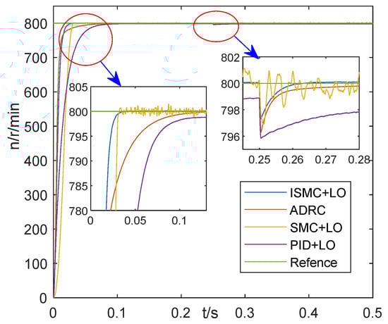
Figure 6.
Speed response curves under adding sudden load.
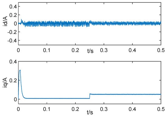
Figure 7.
current response curves under adding sudden load.
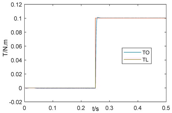
Figure 8.
Torque observer output curves.
Table 3.
Property index of four control methods under adding sudden load.
It can be seen from Figure 6 that the control strategy proposed in this paper has a smaller chattering amplitude compared to SMC + LO. As is shown in Figure 8, the load torque observer can quickly and accurately observe the external load torque.
To verify the tracking of the controller, comparative simulation experiments with variable speed are conducted. Figure 9 shows the tracking response curves of the control strategy proposed in this paper, SMC + LO, ADRC, and PID + LO. Figure 10 is current response curves of the proposed control strategy in this paper. The performance of four control methods under variable speed tracking is summarized in Table 4. As can be seen from Table 4, when changes from 0 to 800, the regulation time of ISMC + LO is the same as that of SMC + LO. The regulation time of ISMC + LO is 29% and 23% of that of ADRC and PID + LO, respectively. When changes from 800 to 1000, the regulation time of ISMC + LO is the same as that of SMC + LO. The regulation time of ISMC + LO is 29% and 13.8% of that of ADRC and PID + LO, respectively. When changes from 1000 to 600, the regulation time of ISMC + LO is the same as that of SMC + LO, and the regulation time of ISMC + LO is 20% of that of ADRC and PID + LO.
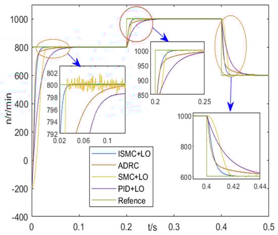
Figure 9.
Speed response curves under variable speed tracking.
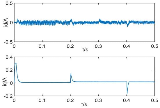
Figure 10.
current response curves under variable speed tracking.
Table 4.
Property index of four control methods under variable speed tracking.
As can be seen from Figure 9, the proposed control strategy has no chattering compared to the SMC + LO, and its regulation time is shorter than those of the PID + LO and ADRC.
4.2. Prototype Experiment
The motor control system includes MOSFET inverter bridge, gate drive, sampling resistor, DSP2837XD, etc. Its structure diagram is shown in Figure 11, and the platform structure diagram is shown in Figure 12. The experimental platform of the permanent magnet synchronous motor speed regulating system control system is shown in Figure 13. The control strategy proposed in this paper is adopted. Given the rated speed of 800 r/min, 0.1 N∙m step load disturbance is added at 0.5 s. Figure 14 is the experimental curve of speed response, Figure 15 is the experimental curve of current, and Figure 16 is the curve of motor output torque. Figure 17 is the experimental curve of torque observation. The output value of the torque observer is 0.1 N∙m, which is the same as the externally applied load torque. The designed torque observer can accurately and quickly observe the externally applied load. By comparing Figure 16 and Figure 17, it can be seen that there is a difference between the torque output by the motor and the observed torque. The reason is that the motor output torque includes the load torque, acceleration torque and viscous torque. Figure 18 is the experimental test curve of tracking the step given speed under no-load condition. It can be seen from the experimental results that the control strategy proposed in this paper has the advantages of no overshoot, short response time, and good immunity.
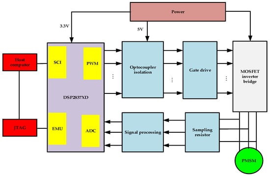
Figure 11.
Motor system control block diagram.
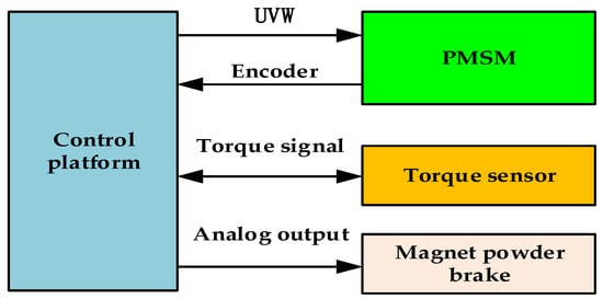
Figure 12.
Platform structure diagram.
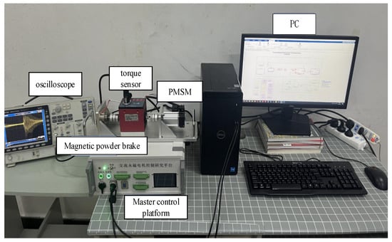
Figure 13.
Experimental prototype.
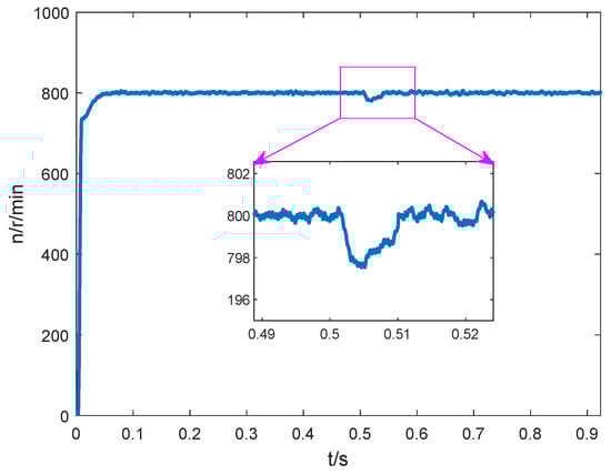
Figure 14.
Experimental curve of speed response.
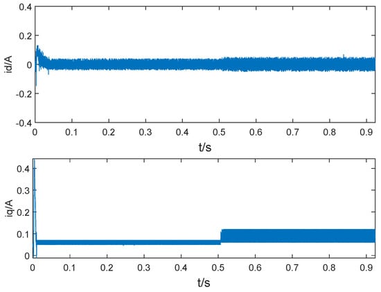
Figure 15.
Experimental curve of current.
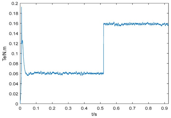
Figure 16.
Curve of motor output torque.
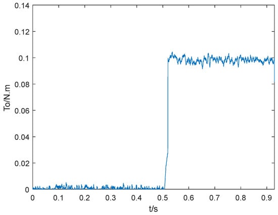
Figure 17.
Curve of torque observation.
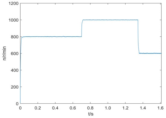
Figure 18.
Speed tracking experimental curve.
By comparing the simulation and experimental results, it can be seen that the dynamic speed drop and recovery time are basically the same when a step disturbance load is suddenly applied. There are glitches in the torque observation and rotational speed obtained from the experimental tests, which are caused by measurement noise and vibration factors, but the average values are the same as those in the simulation.
5. Conclusions
In order to improve the speed control performance for PMSM, an improved sliding mode control method based on load torque observer is proposed. The main contributions of this paper are as follows:
- (1)
- A nonlinear smoothing function with flexible shape adjustment is proposed to replace the symbolic function , and the chattering caused by the discontinuity of the symbolic function is solved;
- (2)
- The fuzzy self-setting algorithm of equal speed switching item parameters and the self-setting rules of exponential switching term parameters for exponential reaching law are proposed, the constant switching term and affecting the system chattering, and the rapidity problem of reaching the sliding mode surface from the initial state are solved;
- (3)
- To achieve rapid suppression of load-torque disturbance, a load torque observer is designed, which only needs the electromagnetic torque and the actual speed of the motor to observe the load torque.
Through the numerical simulation comparison between the strategy proposed in this paper and the conventional sliding mode control, the conventional sliding mode with load torque observer (SMC + LO), as well as the PID control with load torque observer (PID + LO), it is found that when tracking step signals or staircase signals, the regulation time of the control strategy proposed in this paper is the same as that of SMC + LO, which is significantly shorter than that of ADRC and PID + LO, being only 29–20% of the regulation time of ADRC control and 23–13.8% of the regulation time of PID + LO. When a step load is suddenly applied, the dynamic speed drop of the control strategy proposed in this paper is 2.7 r/min, while the dynamic speed drops of SMC + LO, ADRC, and PID + LO are 3.2 r/min, 3.7 r/min, and 4.1 r/min, respectively, and the recovery time is also significantly shorter than that of the other three control strategies. The experimental results are basically consistent with the numerical simulation results. Based on the comprehensive analysis of the simulation and the experiment, the control strategy proposed in this paper can not only ensure the dynamic and static performance of the permanent magnet synchronous motor (PMSM) speed regulation system well, but also effectively improve the robustness of the system and weaken the system chattering.
Author Contributions
Conceptualization, P.X.; Methodology, P.X. and P.L.; Software, P.Q. and P.L.; Validation, P.X. and P.L.; Writing—original draft, P.X. and P.L.; Writing—review and editing, P.Q. All authors have read and agreed to the published version of the manuscript.
Funding
This research was supported by Science and Technology Research Project of the Education Department of Jilin Province, grant number JJKH20240083KJ.
Institutional Review Board Statement
Not applicable.
Informed Consent Statement
Not applicable.
Data Availability Statement
The original contributions presented in this study are included in the article. Further inquiries can be directed to the corresponding author.
Conflicts of Interest
Author Peilin Liu was employed by the company Intelligent Connected Vehicle Development Institute China FAW Group Co., Ltd. The remaining authors declare that the research was conducted in the absence of any commercial or financial relationships that could be construed as a potential conflict of interest.
References
- Fu, X.; Gu, S.; Xiong, J. Review of dq Axis Current Decoupling Strategy for Permanent Magnet Synchronous Motor. Proc. CSEE 2024, 44, 314–332. [Google Scholar]
- Zhao, K.; Dai, W.; Zhou, R.; Leng, A.; Liu, W.; Qiu, P. Novel Model-free Sliding Mode Control of Permanent Magnet Synchronous Motor Based on Extended Sliding Mode Disturbance Observer. Proc. CSEE 2022, 42, 2375–2385. [Google Scholar]
- Ghanayem, H.; Alathamneh, M.; Nelms, R.M. Decoupled Speed and Flux Control of Three-Phase PMSM Based on the Proportional-Resonant Control Method. Energies 2023, 16, 1053. [Google Scholar] [CrossRef]
- Liu, T.; Fadel, M. An Efficiency-optimal Control Method for Mono-inverter dual-PMSM Systems. IEEE Trans. Ind. Appl. 2018, 54, 1737–1745. [Google Scholar] [CrossRef]
- Kawai, H.; Cordier, J.; Kennel, R.; Doki, S. Model predictive current control with a finite set of novel voltages and modulator in permanent magnet synchronous motor drives. IET Electr. Power Appl. 2023, 17, 1197–1211. [Google Scholar] [CrossRef]
- Song, Z.; Zhang, R. Two-step-prediction-horizon-based Variable Vector Action Period Model Predictive Flux Control for Permanent Magnet Synchronous Machines. Proc. CSEE 2021, 41, 5748–5758. [Google Scholar]
- Wang, Y.; Zhu, Y.; Feng, Y.; Tian, B. New Reaching Law Sliding Mode Control Strategy for Permanent Magnet Synchronous Motor. Electr. Power Autom. Equip. 2021, 41, 192–197. [Google Scholar]
- Cruz-Ortiz, D.; Chairez, I.; Poznyak, A. Non-singular terminal sliding-mode control for a manipulator robot using a barrier Lyapunov function. ISA Trans. 2022, 121, 268–283. [Google Scholar] [CrossRef]
- Mosin, M.; Popov, N.; Domakhin, E.; Vilberger, M. Justification of the application of the sliding mode method for controlling the speed of the PMSM at hydrogen energy units. Int. J. Hydrogen Energy 2025, 98, 590–593. [Google Scholar] [CrossRef]
- Chigane, K.; Ouassaid, M. Experimental assessment of integral-type terminal sliding mode control designed for a single-phase grid-interlinked PV system. Control Eng. Pract. 2024, 147, 105903. [Google Scholar] [CrossRef]
- Sajjad Moosapour, S.; Mehdipour, H.; Keramatzadeh, M. Sliding Mode Disturbance Observer-Based Control of a Laboratory Twin Rotor Multi Input-Multi Output System. IEEE Access 2025, 13, 394–406. [Google Scholar] [CrossRef]
- Belkhier, Y.; Oubelaid, A. Passivity-Based Control of PMSM Servo System with Load Torque Adaptation: Theoretical and Experimental Validation. IEEE Trans. Transp. Electrif. 2025, 11, 4494–4503. [Google Scholar] [CrossRef]
- Zhang, R.; Zhou, C.; Shi, P. Multi-PMSM Synchronous Control Based on Adaptive Integral Sliding Mode and Disturbance Observation. Power Syst. Prot. Control 2022, 50, 127–137. [Google Scholar]
- Zhang, W.J.; Du, H.B.; Zhu, W.W.; Wang, L.N. Finite-time Speed Sensorless Control of Permanent Magnet Synchronous Motor Based on Generalized Ssuper-twisting Algorithm. Control Theory Appl. 2021, 38, 833–841. [Google Scholar]
- Zhang, H.; Bi, K. Anti-load Disturbance Control of Permanent Magnet Synchronous Motor Based on LT-FOSMO. Control Eng. China 2022, 29, 2257–2264. [Google Scholar]
- Benhamida, I.; Ameur, A.; Kouzi, K.; Gaoui, B. Torque Ripple Minimization in Predictive Torque Control Method of PMSM Drive Using Adaptive Fuzzy Logic Modulator and EKF Estimator. J. Control Autom. Electr. 2019, 30, 1007–1018. [Google Scholar] [CrossRef]
- Chen, Q.; Xu, C.; Sun, M. Extended State Observer-based Repetitive Learning Control for Permanent Magnet Synchronous Motors. Control Theory Appl. 2021, 38, 1372–1380. [Google Scholar]
- Zhou, Q.; Liu, F.; Gong, H. Model Predictive Torque and Stator Flux Control Method for PMSM with Prediction Error Compensation. Trans. China Electrotech. Soc. 2022, 37, 5728–5739. [Google Scholar]
- Nguyen, T.A. Fuzzy sliding mode control based on an adaptive sliding surface and extended state observer for automotive electric power steering. Adv. Mech. Eng. 2025, 17, 16878132251315517. [Google Scholar] [CrossRef]
- Qian, J.; Ji, C.; Pan, N.; Wu, J. Improved Sliding Mode Control for Permanent Magnet Synchronous Motor Speed Regulation System. Appl. Sci. 2018, 8, 2491. [Google Scholar] [CrossRef]
- Wang, Q.; Yu, H.; Wang, M.; Qi, X. An Improved Sliding Mode Control Using Disturbance Torque Observer for Permanent Magnet Synchronous Motor. IEEE Access 2019, 7, 36691–36701. [Google Scholar] [CrossRef]
- Liu, D.; Han, J.; Chen, G.; Cheng, Y.; Liang, X.; Song, C. Fuzzy self-tuning fractional order PD permanent magnet synchronous motor speed control based on torque compensation. Sci. Rep. 2025, 15, 2141. [Google Scholar] [CrossRef] [PubMed]
- Huang, J.; Zhang, Z.; Han, J.; Jiang, W. Sliding mode control of permanent magnet generator system based on improved exponential rate reaching law. IET Electr. Power Appl. 2020, 14, 1154–1162. [Google Scholar] [CrossRef]
- Jin, Y.; Du, M.; Han, J.; Liu, D. Research on Self-tuning Fractional Order PID Speed Control of Permanent Magnet Synchronous Motor Based on Torque Observer Compensation. In Proceedings of the 2024 12th International Conference on Smart Grid and Clean Energy Technologies (ICSGCE), Jilin, China, 18–20 October 2024; pp. 8–13. [Google Scholar]
Disclaimer/Publisher’s Note: The statements, opinions and data contained in all publications are solely those of the individual author(s) and contributor(s) and not of MDPI and/or the editor(s). MDPI and/or the editor(s) disclaim responsibility for any injury to people or property resulting from any ideas, methods, instructions or products referred to in the content. |
© 2025 by the authors. Licensee MDPI, Basel, Switzerland. This article is an open access article distributed under the terms and conditions of the Creative Commons Attribution (CC BY) license (https://creativecommons.org/licenses/by/4.0/).