Article

Mathematical Modeling and Electromagnetic Characteristics Analysis of a Six-Phase Distributed Single-Winding BPMSM with 12 Slots and 2 Poles

Department of Electrical Engineering, Henan University of Science and Technology, Luoyang 471023, China
*
Author to whom correspondence should be addressed.
Appl. Sci. 2025, 15(4), 2093; https://doi.org/10.3390/app15042093
Submission received: 9 January 2025 / Revised: 8 February 2025 / Accepted: 11 February 2025 / Published: 17 February 2025
(This article belongs to the Special Issue Power Electronics and Motor Control)

Abstract

:

Featured Application

The structural andelectromagnetic characteristics of single-winding BPMSMs indicate their broad application prospects in the fields of flywheel energy storage, aerospace engineering, and biomedical science.

Abstract

This work focuses on small bearingless permanent magnet synchronous motors (BPMSMs). In order to enhance its torque control stiffness and improve the stability of its torque and magnetic levitation force dynamic waveforms, a novel six-phase distributed single-winding BPMSM with 12 slots and 2 poles (six-phase DSW-12/2-BPMSM) is proposed and researched in this work. First, the structure and working principle of the six-phase DSW-12/2-BPMSM are analyzed. Subsequently, considering the relative permeability of permanent magnets, mathematical models of the inductance matrix, electromagnetic torque and radial magnetic levitation force are established. Then, using the finite element method (FEM), the control characteristics of the electromagnetic torque and magnetic levitation force of the six-phase DSW-12/2-BPMSM are analyzed, and the mathematical model is verified. Finally, FEM simulation analysis and comparisons are conducted with a commonly used six-phase centralized single-winding BPMSM with 6 slots and 2 poles (six-phase CSW-6/2-BPMSM). The research results show that the established mathematical model is effective and accurate compared with the six-phase CSW-6/2-BPMSM. The six-phase DSW-12/2-BPMSM has greater torque control stiffness, its dynamic waveforms of torque and radial magnetic levitation force have higher quality and stability, and the coupling degree between its torque and radial magnetic levitation force is lower.

1. Introduction

Although magnetic bearings have solved the rotor support problem in high-speed motors [1], they still have the disadvantages of high power consumption for magnetic levitation control, long rotor shafts, and limited critical speed, etc. [2,3]. A bearingless motor is a new type of magnetic levitation motor that integrates rotary drive and rotor levitation functions [4]. It not only overcomes the shortcomings of AC motors with magnetic bearings, such as low power density, high power consumption of the control system, and high cost, but also has the advantages of a high critical rotational speed and ease of microminiaturization [2,5]. Therefore, it has broad application prospects in the fields of advanced manufacturing, flywheel energy storage, aerospace engineering, etc. [2,6,7,8,9]. Currently, bearingless motors generally adopt a dual-winding structure; that is, the torque winding and levitation winding are simultaneously embedded in the stator to achieve radial levitation and rotational drive control of the bearingless rotor, respectively [2,7]. However, the existence of independent levitation windings reduces the slot occupancy rate of torque winding, thereby reducing the motor power density. Therefore, the development of a single-winding structure for bearingless motors has become an inevitable trend [2,9,10,11].
The single-winding structures of bearingless motors includes bridge winding [10], parallel DPNV winding [11], midpoint injected winding [9], multiphase winding [12], etc. Among them, multiphase bearingless permanent magnet synchronous motors (BPMSMs) not only have high working efficiency, excellent speed regulation performance, and the high reliability characteristics of permanent magnet synchronous motors, but also offer the advantages of multiphase motors, such as multiple degrees of freedom and less harmonic content. Thus, they have gradually become an international research hotspot in the field of high-speed motors [2,12,13]. Reference [12] investigated a five-phase BPMSM with 30 slots and 4 poles, established an inductance model, and performed validation analysis. For the two-pole torque system and four-pole levitation system of a six-phase BPMSM, reference [13] proposed a structure and control strategy for a parallel dual three-phase BPMSM with 24 slots and 4 poles. In the low-power field, stator structures with 12 or fewer slots are most commonly adopted [14,15,16]. Reference [14] studied a six-phase BPMSM with 6 slots and 2 poles, analyzed the fault-tolerant performance advantages of the multiphase BPMSM, and experimentally proved the correctness of the mathematical model. Reference [15] proposed a dual three-phase control method for a single-winding BPMSM with a two-pole torque system and a four-pole suspension system, carried out electromagnetic characteristic tests on a prototype machine, and gave the calculation results of the control parameters. Reference [16] studied a five-phase motor with 10 slots and 8 poles and optimized the levitation performance using a harmonic injection method. However, the magnetic levitation force waveform of a BPMSM usually has obvious fluctuations, meaning that the rotor levitation performance can only be improved through an external closed-loop control system. This makes it inconvenient for the promotion and application of bearingless motor technology in the low-power field [2].
In this work, to meet the requirements for single-winding bearingless motor technology in the low-power field, a six-phase distributed single-winding BPMSM with 12 slots and 2 poles (six-phase DSW-12/2-BPMSM) is researched, and detailed modeling and electromagnetic characteristic analyses are conducted. First, the control principles of electromagnetic torque and magnetic levitation force are analyzed, and mathematical models of the inductance matrix, electromagnetic torque, and magnetic levitation force are established. Then, using the finite element analysis method (FEM), electromagnetic characteristics analyses of the six-phase DSW-12/2-BPMSM are carried out, and a comparison with a commonly used six-phase centralized single-winding BPMSM with 6 slots and 2 poles (six-phase CSW-6/2-BPMSM) is conducted.

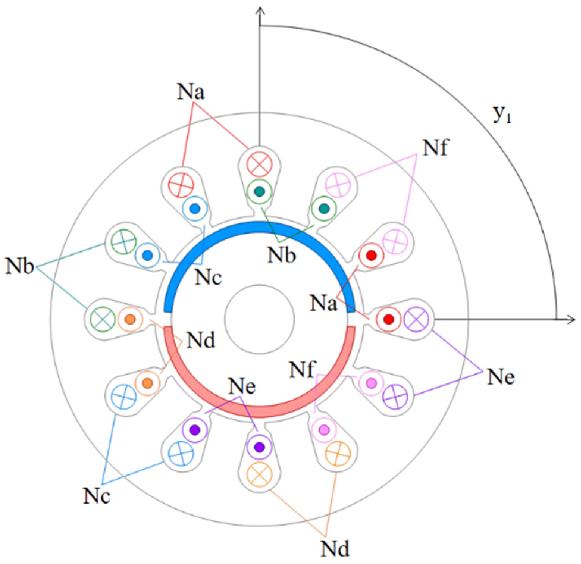
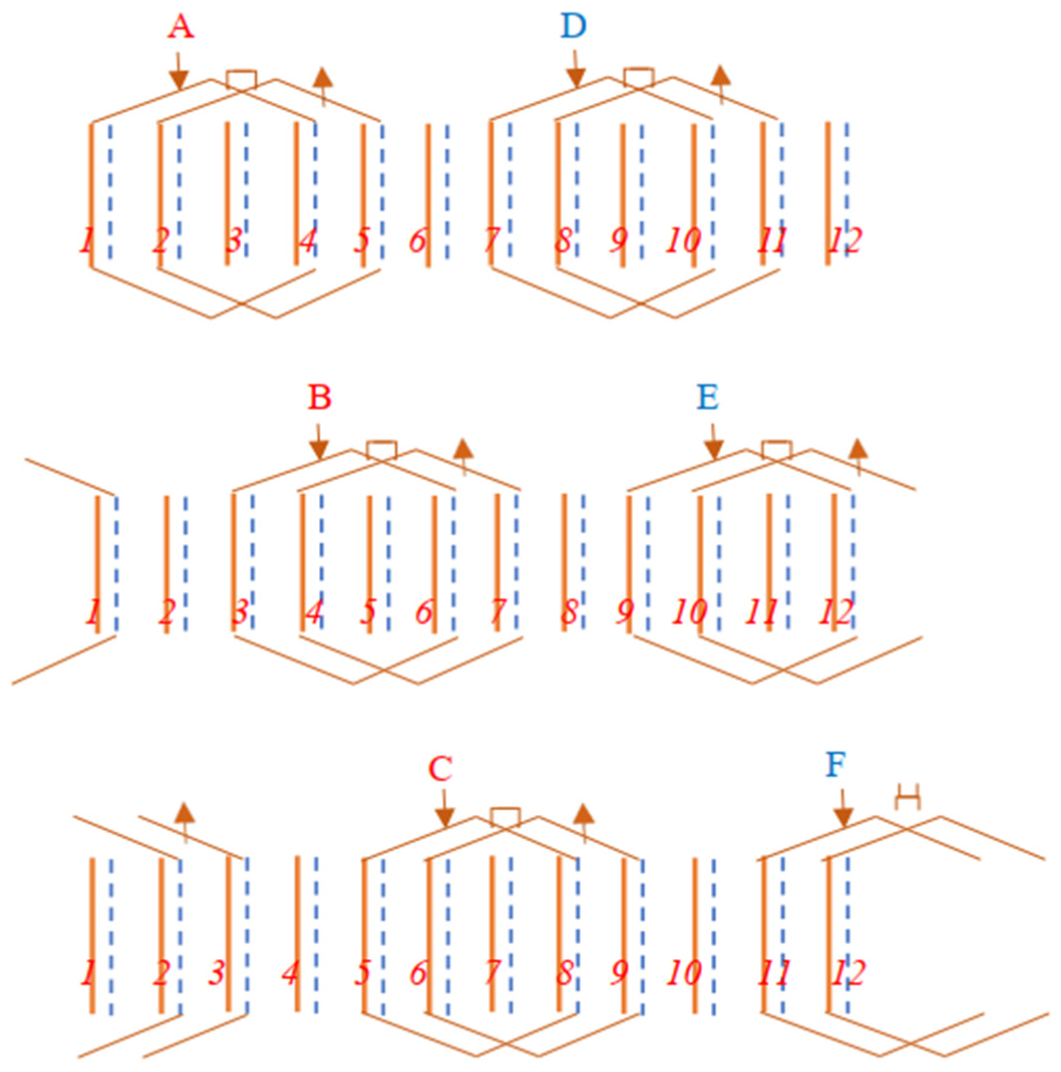
2. Structure and Working Principle of the Six-Phase DSW-12/2-BPMSM

Figure 1 and Figure 2 show the structure and winding unfolding schematic of the six-phase DSW-12/2-BPMSM, respectively. The stator has 12 slots, with a two-pole torque system and a four-pole suspension system. The number of slots per phase per pole is one, and the coil span y1 is three. A double-layer distributed winding structure is adopted, i.e., each slot contains both the upper and lower coil-edges. The six-phase symmetrical distribution winding structure which contains A, B, C, D, and E phase windings is formed by 12 stator coils. Adjacent two-phase windings differ by a 60° electrical angle. A two-pole surface-mounted permanent magnet structure is adopted, and a parallel magnetization method is adopted for each permanent magnet.
According to the working principle of a multiphase motor, when a six-phase symmetrical stator winding is energized with a six-phase symmetrical torque current with a time-phase difference of 60 degrees, the generated two-pole armature reaction field interacts with the permanent magnetic field of the two-pole rotor to produce a stable electromagnetic torque that drives the rotor to rotate. Meanwhile, when levitation currents with a time-phase difference of 120 degrees are injected sequentially into the six symmetrical phase windings, a rotating four-pole levitation magnetic field can be generated. After the two-pole motor magnetic field is superimposed with the four-pole levitation magnetic field, the symmetrical equilibrium distribution of the original air gap magnetic field will be broken; thus, a radial electromagnetic force acting on the rotor will be generated. At this point, if the angular frequencies of the torque current and levitation current are equal, the generated radial electromagnetic force will be controllable, allowing it to be used for rotor levitation control.
Figure 3 gives the schematic diagram of the generation principle of radial magnetic levitation force. As shown in Figure 3, the air gap magnetic field after superposition is enhanced on the upper side and weakened on the lower side, and a radial levitation force will be generated along the positive y-axis direction. Similarly, the radial magnetic levitation force along the x-axis can be generated by adjusting the phase of the four-pole levitation magnetic field. The magnitude and phase of the resultant radial controllable magnetic levitation force can be controlled by changing the magnitude and phase of the levitation current; then, the levitation control of the BPMSM rotor can be realized.

3. Mathematical Modeling of the Six-Phase DSW-12/2-BPMSM

3.1. Basic Model for Six-Phase DSW-12/2-BPMSM

One of the conditions for realizing rotor levitation is that the pole-pair numbers of the torque magnetic field and the levitation magnetic field must differ by one. However, in a typical multiphase AC motor with symmetrical windings, there are generally only odd harmonics but no even harmonics; that is to say, there is no even magnetic field in a common multiphase motor [12]. Therefore, the six-phase DSW-12/2-BPMSM in this work adopts a modified winding structure. Specifically, the common full-pole distribution winding is replaced by a half-pole distribution winding for each phase, so that each phase winding is asymmetrical regarding the air gap circumference.
Next, the magnetomotive force of the improved winding is analyzed, which depends on the winding structure of the six-phase DSW-12/2-BPMSM and the excitation current. Here, the winding structure is expressed by a winding function, which refers to the spatial distribution function of the magnetomotive force generated by the unit excitation current along the air gap circumference. For the convenience of analysis, the winding function is expressed using Fourier series decomposition. The axis of the A-phase winding is set to the 0° position. Then, the winding function of each phase can be obtained as follows:
{ N a = N 1 cos ( θ ) + N 2 cos ( 2 θ ) + N b = N 1 cos ( θ π 3 ) + N 2 cos ( 2 ( θ π 3 ) ) + N c = N 1 cos ( θ 2 π 3 ) + N 2 cos ( 2 ( θ 2 π 3 ) ) + N f = N 1 cos ( θ 5 π 3 ) + N 2 cos ( 2 ( θ 5 π 3 ) ) +
where N1 and N2 are the first and second space harmonic magnitudes of the winding distribution function, respectively, which can be obtained using Fourier decomposition for each phase winding function, as follows:
N 1 = 4 π N 2 sin ( 1 2 y 1 α 1 ) ,   N 2 = 2 π N 2 sin ( y 1 α 1 )
where N is the number of series turns per phase winding and α1 is the slot pitch angle.
Figure 4 shows the schematic diagram of the rotor eccentricity, where θ is the spatial position angle along the air gap circumference, g0 is the average value of the equivalent air gap length, λ is the eccentric angle of the rotor, d is the eccentric distance, and α and β are the radial displacement components along the horizontal and vertical directions, respectively. From Figure 4, the air gap length at any angle θ position can be expressed as follows:
g ( θ , λ ) = g 0 d cos ( θ λ )
Then, the inverse air gap function is as follows:
P e ( θ , λ ) = 1 g ( θ , λ ) = 1 g 0 d cos ( θ λ )
In order to improve the calculation accuracy of the established analytical model, this work simultaneously considers the influence of the thickness and relative magnetic permeability parameters of the permanent magnet on the average equivalent air gap length g0. For the surface-mounted permanent magnet motor in this work, the calculation expression of g0 is as follows:
g 0 = g + L m μ r
where g is the actual air gap length, and Lm and μr are the thickness and relative permeability of the permanent magnet, respectively.
During the operation of a six-phase DSW-12/2-BPMSM, the rotor eccentricity will result in uneven distribution of the air gap length. Then, the inductance can be calculated by the improved winding method [17]. The calculation model for the inductance of the six-phase BPMSM with a surface-mounted permanent magnet rotor is established as Equation (6).
L i j = 2 π μ 0 l r [ P e N i N j P e N i P e N j P e ]
where μ0 is the vacuum permeability, l is the stator core length, r is the rotor radius, and Ni and Nj are the winding functions of phases i and j (i, j = a, b, c, d, e, f), respectively. The operator <f> denotes that the function f takes the average value over the air gap circumference.
Substituting Equation (1) into Equation (6) yields the following:
L i j = 2 π μ 0 l r { 1 2 P e N 1 2 cos [ π 3 ( i j ) ]   + 1 2 P e N 2 2 cos × [ 2 π 3 ( i j ) ] + d 4 P e 2 N 1 N 2 cos [ λ + π 3 ( i 2 j ) ] }
Based on the multidimensional control characteristics of a multiphase motor [18], a coordinate transformation matrix C can be established, which can transform the mathematical model of the six-phase BPMSM from the six-phase stationary coordinate system to the synchronous coordinate system, as shown in Equation (8).
C = 1 3 [ cos θ cos ( θ 1 3 π ) cos ( θ 2 3 π ) cos ( θ 3 3 π ) cos ( θ 4 3 π ) cos ( θ 5 3 π ) sin θ sin ( θ 1 3 π ) sin ( θ 2 3 π ) sin ( θ 3 3 π ) sin ( θ 4 3 π ) sin ( θ 5 3 π ) cos 2 θ cos ( 2 θ 2 3 π ) cos ( 2 θ 4 3 π ) cos ( 2 θ 6 3 π ) cos ( 2 θ 8 3 π ) cos ( 2 θ 10 3 π ) sin 2 θ sin ( 2 θ 2 3 π ) sin ( 2 θ 4 3 π ) sin ( 2 θ 6 3 π ) sin ( 2 θ 8 3 π ) sin ( 2 θ 1 3 π ) 1 2 1 2 1 2 1 2 1 2 1 2 1 2 1 2 1 2 1 2 1 2 1 2 ]
Setting the xy axis as the synchronous coordinate system of the mechanical rotor, θ in Equation (8) represents the included angle in the mechanical space between the rotor magnetic flux linkage and the axis of the A-phase winding (i.e., the rotor position angle) as θ = ωt, where ω is the rotation speed. The first two rows of the matrix correspond to the dq torque plane in the electrical space; the middle two rows of the matrix correspond to the jk levitation plane in the electrical space, with the electrical angular velocity of the jk plane being twice that of the dq plane; and the last two rows of the matrix correspond to the zero space.
Taking the inductance parameter Lij (i, j = a, b, c, d, e, f) in Equation (7) as elements, the inductance matrix Ls of the stator winding of the six-phase BPMSM can be constituted as follows:
L S = [ L a a M a b M a c M a d M a e M a f M b a L b b M b c M b d M b e M b f M c a M c b L c c M c d M c e M c f M d a M d b M d c L d d M d e M d f M e a M e b M e c M e d L e e M e f M f a M f b M f c M f d M f e L f f ]
By performing coordinate transformation on the inductance matrix Ls using Equation (8), the corresponding inductance matrix in the xy coordinate system can be obtained as follows:
L x y = [ L 1 d 4 g 0 2 + d 2 4 g 0 2 0 M 1 d 2 j M 1 d 2 k 0 L 1 q 4 g 0 2 + d 2 4 g 0 2 M 1 q 2 j M 1 q 2 k M 1 d 2 j M 1 q 2 j L 2 j 4 g 0 2 + d 2 4 g 0 2 0 M 1 d 2 k M 1 q 2 k 0 L 2 k 4 g 0 2 + d 2 4 g 0 2 ]
[ L 1 d 0 M 1 d 2 j M 1 d 2 k 0 L 1 q M 1 q 2 j M 1 q 2 k M 1 d 2 j M 1 q 2 j L 2 j 0 M 1 d 2 k M 1 q 2 k 0 L 2 k ]
where L1d and L1q are the dq axis inductance components in the torque plane; L2j and L2k are the jk axis inductance components in the suspension plane; and M1d2j, M1d2k, M1q2j, and M1q2k represent the mutual inductance between the torque windings and suspension windings. The expression of the stator mutual inductance matrix is as follows:
[ M 1 d 2 j M 1 d 2 k M 1 q 2 j M 1 q 2 k ] = M 12 d [ cos ( ω t λ ) sin ( ω t λ ) sin ( ω t λ ) cos ( ω t λ ) ] = M 12 [ α β β α ] [ cos ( ω t ) sin ( ω t ) sin ( ω t ) cos ( ω t ) ]
The transformation relationship between the synchronous xy coordinate system of the rotor and the stationary αβ coordinate system is as follows:
[ x y ] = [ cos ( ω t ) sin ( ω t ) sin ( ω t ) cos ( ω t ) ] [ α β ]
Combining Equations (9)–(12), the inductance matrix in the xy coordinate system is obtained as follows:
L x y = [ L 1 0 M 12 x M 12 y 0 L 1 M 12 y M 12 x M 12 x M 12 y L 2 0 M 12 y M 12 x 0 L 2 ]
where the self-inductance coefficients L1 and L2 of the equivalent two-phase torque winding and suspension winding, as well as the mutual inductance coefficient M12 between them, can be expressed as follows:
{ L 1 = L 1 d = L 1 q = 3 π μ 0 l r N 1 2 / g 0 L 2 = L 2 d = L 2 q = 3 π μ 0 l r N 2 2 / g 0 M 12 = 3 π μ 0 l r N 1 N 2 / 2 g 0 2
where N1 and N2 are the turn numbers of the equivalent two-phase torque winding and suspension winding, respectively.
In the stationary coordinate system, the voltage equation and torque equation are as follows:
U S = R S I S + d Ψ S d t
T e = P e Ω = E I S Ω
where US is the phase winding voltage, RS is the phase winding resistance, IS is the phase winding current, ΨS is the phase winding magnetic chain, Pe is the electromagnetic power, Ω is the mechanical angular speed of the rotor, and E is the counter electromotive force, whose value is equal to the change rate of flux linkage, as follows:
E = d Ψ S / d t
The flux linkage ΨS of each phase winding consists of the flux linkage generated by the winding itself, the coupled mutual inductance flux linkage generated by other phase windings, and the flux linkage generated by the permanent magnet. The expression of ΨS is as follows:
Ψ S = L S I S + Ψ f ( θ )
where Ψf is the equivalent flux linkage generated by the permanent magnet in the phase winding.
The mathematical model of the six-phase DSW-12/2-BPMSM in the synchronous coordinate system can be obtained using coordinate transformation. The voltage equation, torque equation, and flux linkage equation are as follows:
[ u 1 d u 1 q u 2 j u 2 k ] = R S [ i 1 d i 1 q i 2 j i 2 k ] + L x y d d t [ i 1 d + i f i 1 q i 2 j i 2 k ]               + ω [ 1 0 0 0 0 1 0 0 0 0 2 0 0 0 0 2 ] L x y [ i 1 q i 1 d + i f i 2 j i 2 k ]
T e = ( i 1 q Ψ 1 d i 1 d Ψ 1 q ) + 2 ( i 2 k Ψ 2 j i 2 j Ψ 2 k )
{ Ψ 1 d = L 1 d ( i 1 d + i f ) , Ψ 1 q = L 1 q i 1 q Ψ 2 j = L 2 j i 2 j , Ψ 2 k = L 2 k i 2 k
In the above equations, f1d, f1q and f2j, f2k denote the dq axis components in the torque plane and the jk axis components in the levitation plane, respectively; if is the equivalent current of the permanent magnet; and the magnitudes of i1d, i1q and i2j, i2k are 1.732 times the magnitude of IS.
Here, the torque system adopts the “i1d = 0” control method; then, the voltage and flux linkage equations can be further simplified as follows:
{ u 1 d = ω L 1 i 1 q u 1 q = R S i 1 q + L 1 d d t i 1 q + ω Ψ f u 2 j = R S i 2 j + L 2 d d t i 2 j 2 ω L 2 i 2 k u 2 k = R S i 2 k + L 2 d d t i 2 k + 2 ω L 2 i 2 j
{ Ψ 1 d = L 1 d i f = Ψ f , Ψ 1 q = L 1 q i 1 q Ψ 2 j = L 2 j i 2 j , Ψ 2 k = L 2 k i 2 k
Since the permanent magnet flux linkage is far larger than the suspension flux-linkage, the electromagnetic torque equation in Equation (20) and the rotational motion equation of the rotor can be further simplified as follows:
T e i 1 q Ψ f
T e T L = J d Ω d t
where TL is the load torque and J is the moment of inertia.

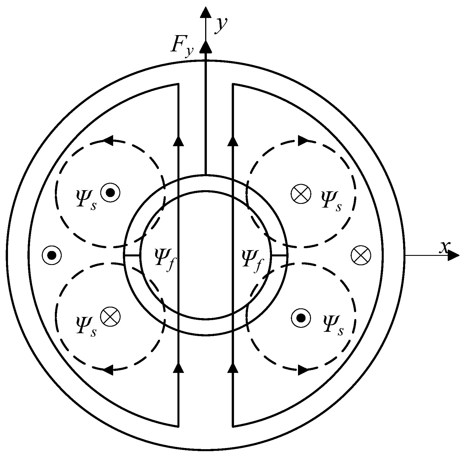
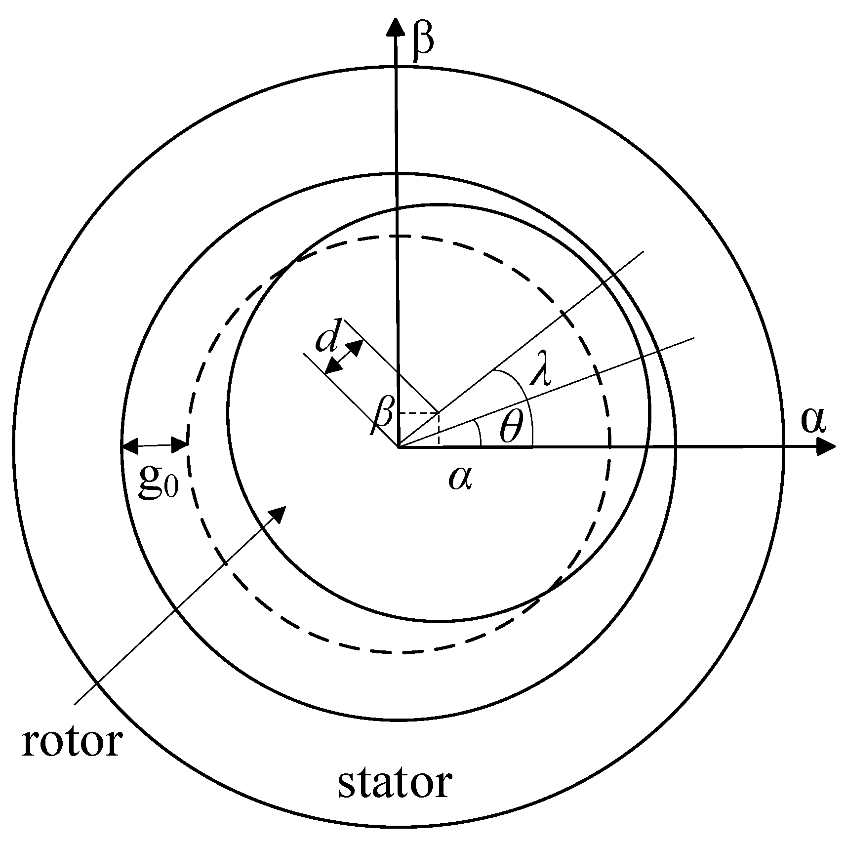
3.2. Magnetic Levitation Force Model of the Six-Phase DSW-12/2-BPMSM

Setting Ixy = [i1d, i1q, i2j, i2k], based on the electromechanical energy conversion principle, the magnetic field energy stored in the motor inductance can be expressed as follows:
W m = I x y T L x y I x y / 2
Based on the virtual displacement principle, the radial electromagnetic force acting on the rotor can be expressed as the partial derivative of the electromagnetic energy storage with respect to the radial displacement. The radial electromagnetic force consists of a controllable magnetic levitation force and an uncontrollable unilateral magnetic pull force. In the xy coordinate system, the expressions of the radial electromagnetic force components Fx and Fy are as follows:
F x = M 12 ( i 2 d i f + i 1 q i 2 q ) +   x 4 g 0 2 [ L 1 ( i f 2 + i 1 q 2 ) + 2 L 2 ( i 2 j 2 + i 2 k 2 ) ]
F y = M 12 ( i 2 q i f i 1 q i 2 d ) +    y 4 g 0 2 [ L 1 ( i f 2 + i 1 q 2 ) + 2 L 2 ( i 2 j 2 + i 2 k 2 ) ]
The first parts in Equations (27) and (28) are the controllable magnetic levitation force components Fix and Fiy, which can be written in matrix form as follows:
[ F i x F i y ] = M 12 [ i f i 1 q i 1 q i f ] [ i 2 j i 2 k ]
For the six-phase DSW-12/2-BPMSM in this work, the torque system and levitation system have two poles and four poles, respectively. Then, in the electrical space, if the dq torque plane and the jk levitation plane jointly correspond to the xy mechanical synchronous coordinate system of the rotor, the rotational speed of the jk levitation plane (or coordinate system) is twice that of the d-q torque plane (or coordinate system) [5]. Thus, if the levitation current in the jk plane is transformed to the dq plane, the following coordinate transformation relations should apply:
[ i 2 d i 2 q ] = [ cos ( ω t ) sin ( ω t ) sin ( ω t ) cos ( ω t ) ] [ i 2 j i 2 k ]
From Equations (29) and (30), the following equation can be obtained by coordinate transformation:
[ F i α F i β ] = [ cos ( ω t ) sin ( ω t ) sin ( ω t ) cos ( ω t ) ] [ F i x F i y ] = M 12 [ i f i 1 q i 1 q i f ] [ i 2 d i 2 q ]
In Equations (30) and (31), F and F are the controllable magnetic levitation force components in the stationary αβ coordinate system, and i2d and i2q are the dq axis components of the levitation current transformed to the torque plane (or coordinate system).
The last two parts in Equations (27) and (28) represent the uncontrollable eccentric magnetic pulling force components, whose expressions are as follows:
{ F e x = x 4 g 0 2 [ L 1 ( i f 2 + i 1 q 2 ) + 2 L 2 ( i 2 j 2 + i 2 k 2 ) ] F e y = y 4 g 0 2 [ L 1 ( i f 2 + i 1 q 2 ) + 2 L 2 ( i 2 j 2 + i 2 k 2 ) ]
where Fex and Fey are the eccentric magnetic pull force components in the xy coordinate system.
Based on Equation (32), the eccentric magnetic pull force along a certain axial direction is proportional to the displacement in this axis. Thus, according to the structural symmetry of the six-phase DSW-12/2-BPMSM, the expressions of the eccentric magnetic pull force components in the stationary αβ coordinate system can be written as follows:
{ F e α = α 4 g 0 2 [ L 1 ( i f 2 + i 1 q 2 ) + 2 L 2 ( i 2 j 2 + i 2 k 2 ) ] F e β = β 4 g 0 2 [ L 1 ( i f 2 + i 1 q 2 ) + 2 L 2 ( i 2 j 2 + i 2 k 2 ) ]
where F and F are the components of the radial eccentric magnetic pull force along the horizontal and vertical directions, respectively, which are unbalanced radial electromagnetic forces.
Considering that the levitation current is generally smaller than the torque current, and much smaller than the equivalent current of the permanent magnet, Equation (33) can be simplified as follows:
F e α L 1 ( i f 2 + i 1 q 2 ) 4 g 0 2 α ,   F e β L 1 ( i f 2 + i 1 q 2 ) 4 g 0 2 β
Equations (31) and (34) together constitute the mathematical model of the radial magnetic levitation force of the six-phase DSW-12/2-BPMSM.
In addition, the suspension motion equations of the rotor along two radial degrees of freedom are as follows:
{ m α ¨ = F i α + F e α + F d α m β ¨ = F i β + F e β + F d β
where m is the rotor mass, and F and F are the radial disturbance force components.

4. FEM Verification and Analysis

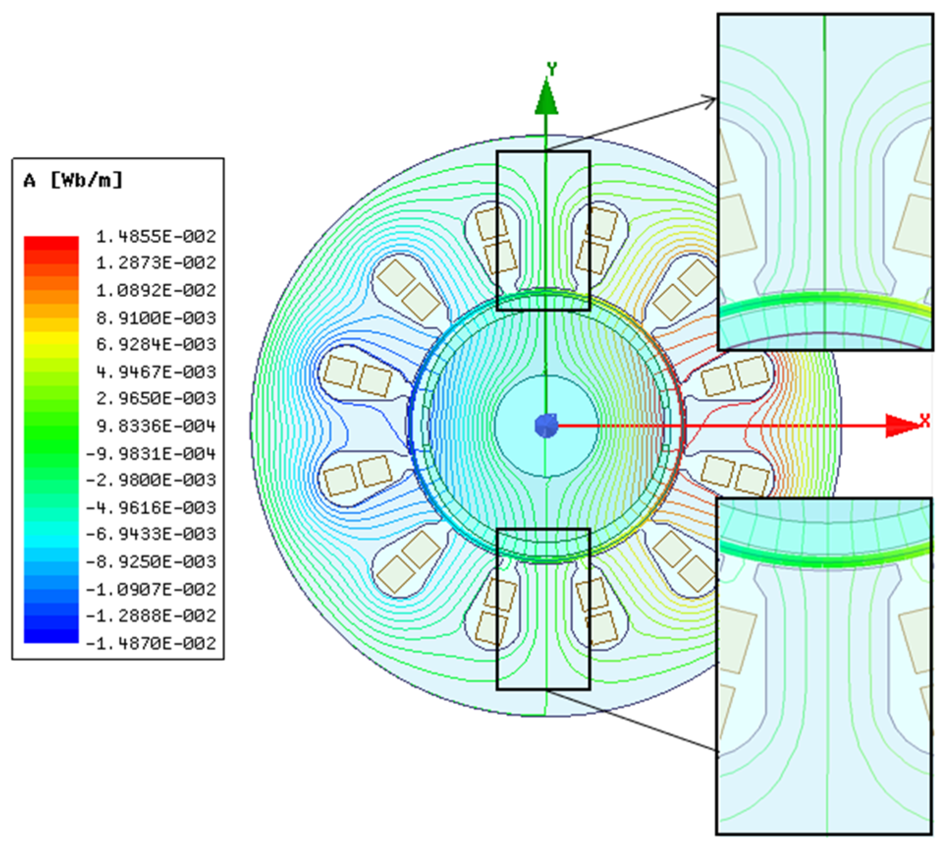
4.1. FEM Analysis Model of the Six-Phase DSW-12/2-BPMSM

A finite element method (FEM) analysis model of the six-phase DSW-12/2-BPMSM was established using Ansys Maxwell software and used for the validation and analysis of the mathematical models of electromagnetic torque and radial magnetic levitation force. The structural parameters of the six-phase DSW-12/2-BPMSM and the settings of the boundary conditions in the FEM analysis are shown in Table 1.
For the six-phase DSW-12/2-BPMSM, Figure 5 gives the distribution diagram of the magnetic force lines at a certain moment after applying the control current of the y-axis magnetic levitation force. In Figure 5, after joining the levitation magnetic field, the magnetic density on the left and right sides of the rotor is still symmetrically distributed. The magnetic lines on the upper side of the rotor are dense, and the magnetic field is strengthened, while the magnetic lines on the lower side of the rotor become sparse and the magnetic field is weakened. Therefore, an electromagnetic force in the positive y-axis direction will be generated at this time.

4.2. Validation Analysis of Electromagnetic Torque and Magnetic Levitation Force Models

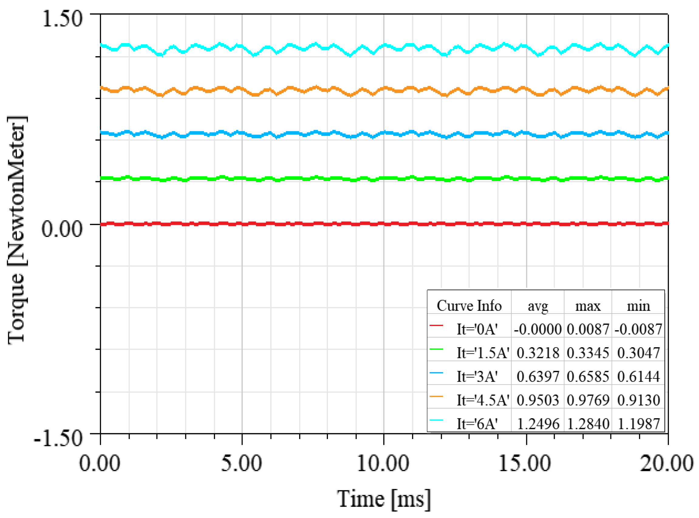
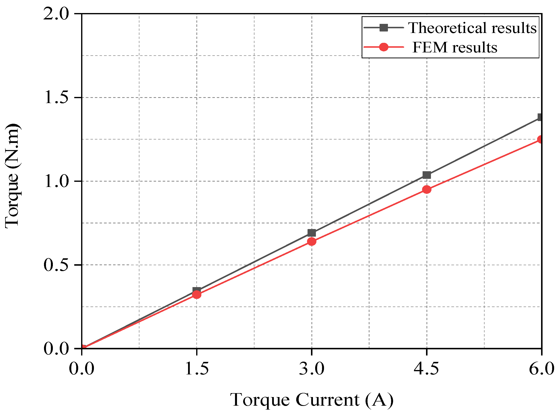
4.2.1. FEM Validation Analysis of Torque Model

Under the condition of zero radial displacement, and within the range of 0–6 A, only torque current was applied to the six-phase winding with a step size of 1.5 A. Figure 6 shows the dynamic waveform of electromagnetic torque over time (or rotor position angle), and Figure 7 shows the comparison curve between the model calculation results and the FEM analysis results for electromagnetic torque. Based on Figure 6 and Figure 7, the following research results were obtained:
(1) The steady-state mean value of the torque is basically proportional to the torque current, and the model calculation value of the torque closely matches the FEM analysis value, with the maximum error between them not exceeding 6.86%. The reason for the error is that the torque model does not take into account the effects of the magnetic pressure drop and magnetic saturation of the iron core, as well as the edge effect of the permanent magnet field and other factors.
(2) Under different torque current excitations, the dynamic waveforms of torque over time (or position angle) are smooth, and the peak-to-peak fluctuation rate is generally maintained at about 9.26%. The dynamic waveform of torque is smooth, and the control performance is good. This is an advantage of multiphase motors, providing a reliable foundation for the stable rotation control of the six-phase DSW-12/2-BPMSM.

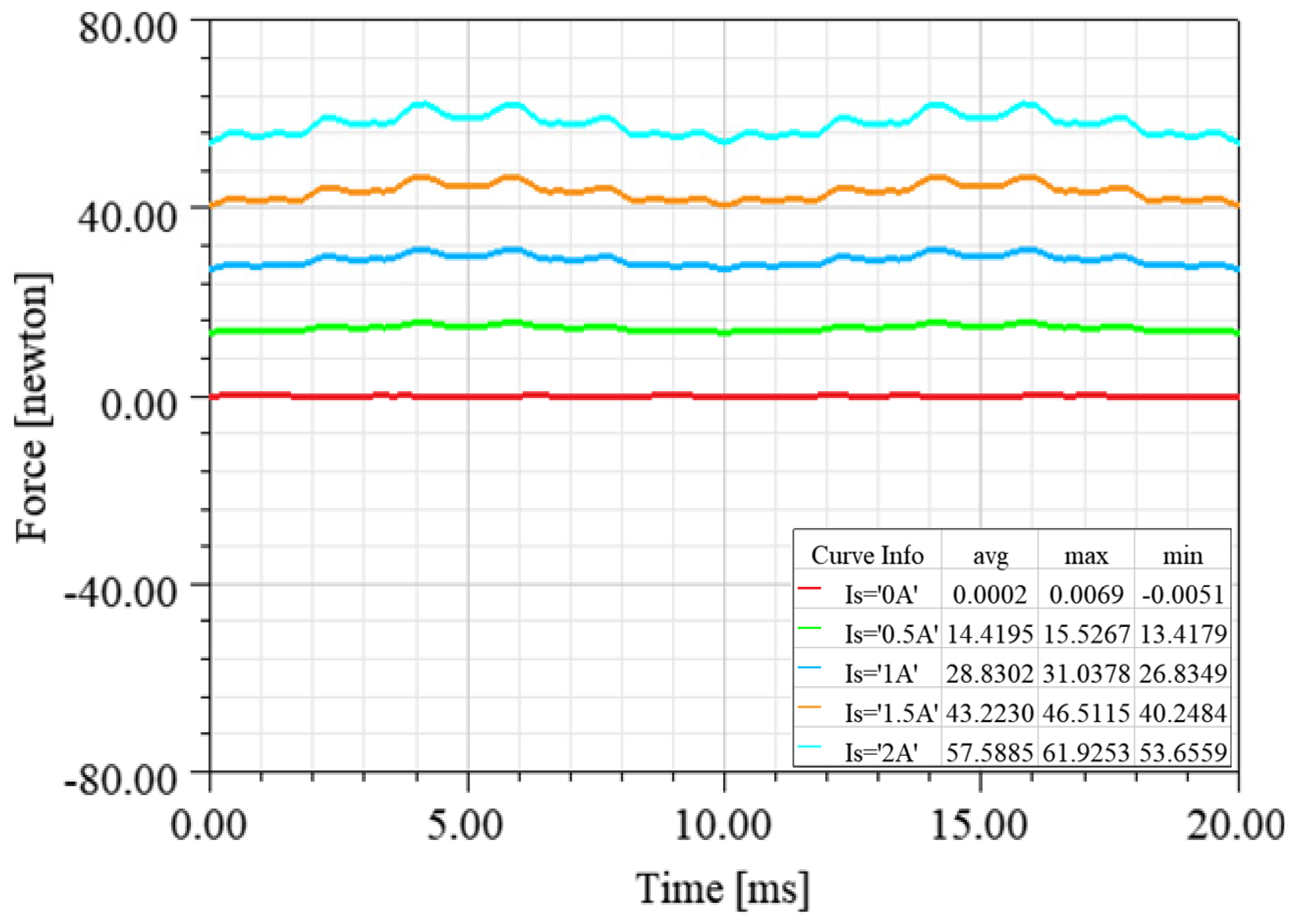
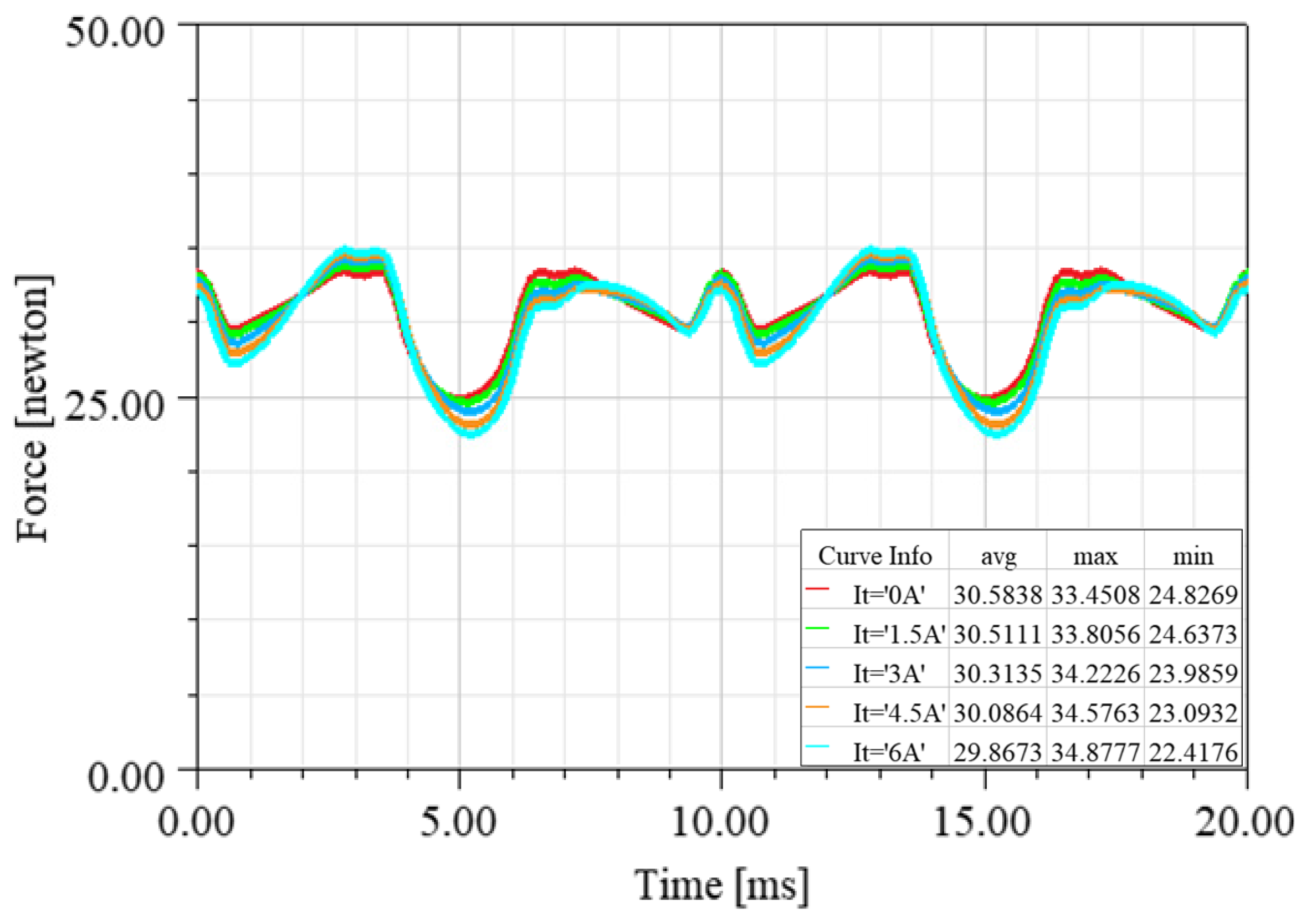
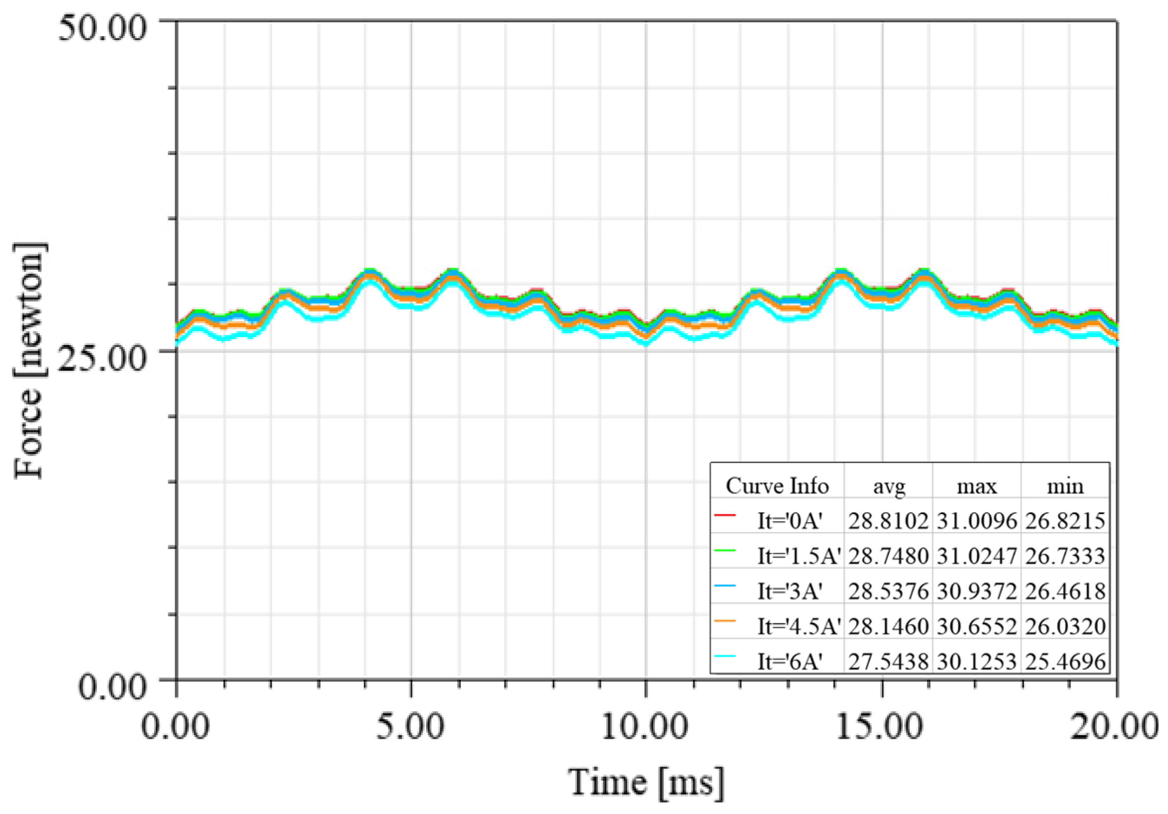
4.2.2. FEM Validation Analysis of Controlled Magnetic Levitation Force Models

With zero radial displacement of the rotor and levitation current applied to the six-phase winding, the dynamic waveforms of the radial magnetic levitation force were observed. The amplitude of the levitation current was set to vary within the range of 0 A to 2 A with a step size of 0.5 A. Figure 8 shows the dynamic waveform of the controlled radial magnetic levitation force with time (or rotor position angle), and Figure 9 shows the comparison between the FEM analysis results of the controllable radial magnetic levitation force and its model calculation results. Based on Figure 8 and Figure 9, the following research results were obtained:
(1) Under the unsaturated magnetic circuit condition, the controllable magnetic levitation force varies proportionally with the levitation current, and the FEM analysis results of the controllable magnetic levitation force are almost in perfect agreement with the model calculation value, with the maximum error between them not exceeding 0.25%. For example, when the levitation current is 1 A, the model-calculated value of the controllable magnetic levitation force is 28.865 N, while its FEM-analyzed value is 28.8302 N, with an error of about 0.12%.
(2) The dynamic waveform of the controllable magnetic levitation force with time (or rotor position angle) shows certain fluctuation characteristics. However, with the increase in levitation current, the peak-to-peak fluctuation rate of the controllable magnetic levitation force is essentially unchanged. For example, when the levitation current is 1 A or 2 A, the maximum peak-to-peak fluctuation rate of the controllable magnetic levitation force is almost the same (about 14.62%). The main reasons for the fluctuation of the controllable magnetic levitation force are twofold: the first is the influence of the harmonic magnetic field, and the second is that the structural parameters of the six-phase DSW-12/2-BPMSM still need to be optimized.
(3) The dynamic fluctuation frequency of the controllable magnetic levitation force is relatively low. When the rotor rotates every mechanical cycle, the controllable magnetic levitation force fluctuates two times; the number of fluctuations is equal to the number of magnetic poles of the torque system. The actual radial displacement is controlled by a closed loop. Therefore, the slow fluctuation of the radial magnetic levitation force will not have a significant impact on the radial displacement control of the rotor.

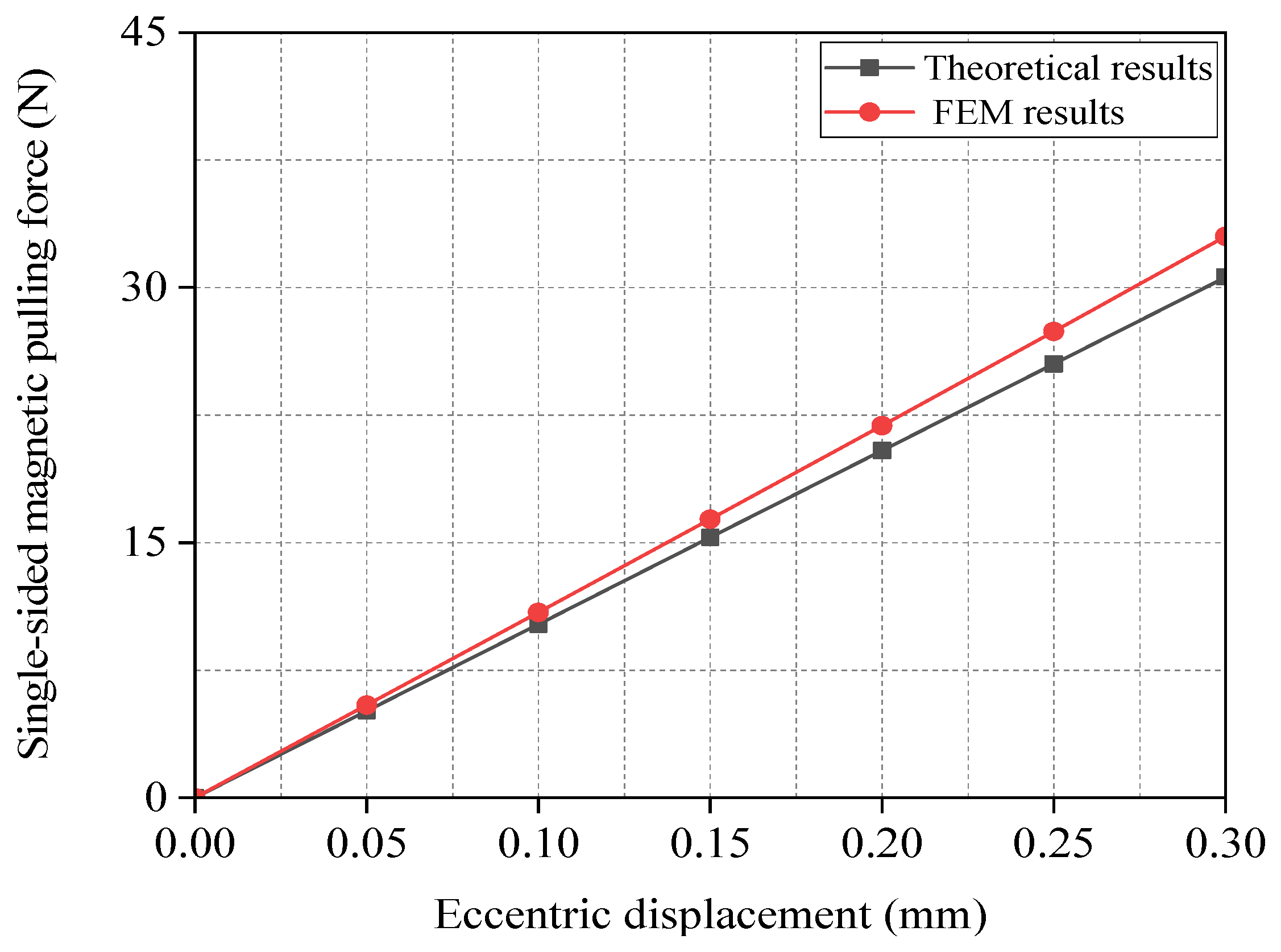
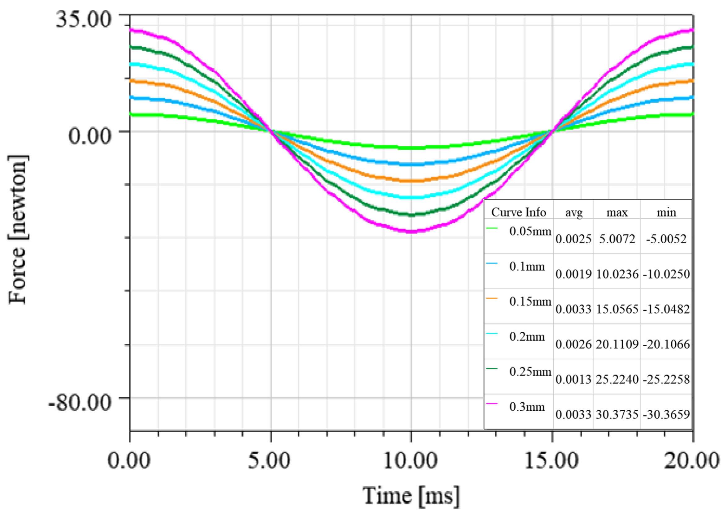
4.2.3. FEM Validation Analysis of Eccentric Magnetic Pull Force Model

In order to verify the mathematical model of the eccentric magnetic pull force, the static eccentric displacement of the rotor was gradually increased along the y-axis within the range of 0 mm to 0.3 mm with a step size of 0.05 mm. Since the armature’s reflected magnetic potential is generally much lower than that of the permanent magnets, the FEM analysis was performed under the condition of zero armature current.
Figure 10 shows the dynamic waveform of the eccentric magnetic pull force with time (or rotor position angle), and Figure 11 shows the comparison between the FEM analysis results of the eccentric magnetic pull force and its model calculation results. Based on Figure 10 and Figure 11, the following research results were obtained:
(1) In the case of an unsaturated magnetic circuit, when the rotor experiences static eccentricity along the positive y-axis direction, the resultant eccentric magnetic pull force is directly proportional to the static eccentricity displacement.
(2) The calculated values of the eccentric magnetic pulling force model are consistent with the FEM analysis values. For example, when the eccentric distance of the rotor is 0.1 mm, the model-calculated value of the eccentric magnetic pull force is 10.2035 N, while its FEM analysis value is 10.9014 N, and the error between them is about 6.4%. The main reason for the calculation error is that the influence of the harmonic magnetic potential was not considered in the process of deriving the radial electromagnetic force model based on the virtual displacement method. To obtain a more accurate model of eccentric magnetic pull force, it can be equipped with a calibration coefficient kec of about 1.072 (here, kec is equal to 1.068).
Due to machining accuracy and other reasons, it is inevitable that the rotor will have different degrees of mass eccentricity, which will excite the rotor to produce periodic dynamic eccentric displacement. Under the conditions of different dynamic eccentric distances, based on the FEM analysis model of the six-phase DSW-12/2-BPMSM, Figure 12 shows the dynamic waveform of the eccentric magnetic pull force along the y-axis direction as a function of time (or rotor position angle). The waveform of the eccentric magnetic pull force along the x-axis direction has a 90-degree phase difference with that along the y-axis direction, which is omitted here.
From Figure 12, it can be seen that the eccentric magnetic pull force changes dynamically with time (or rotor position angle) in a sinusoidal pattern under the dynamic eccentricity condition of the rotor. At the same eccentric distance, the amplitude of the dynamic eccentric magnetic pull force is consistent with the FEM analysis value and model calculation value of the static eccentric magnetic pulling force (refer to Figure 10). Therefore, the FEM experimental results of the dynamic eccentric magnetic pull force prove the validity of the eccentric magnetic pull force model from another side.

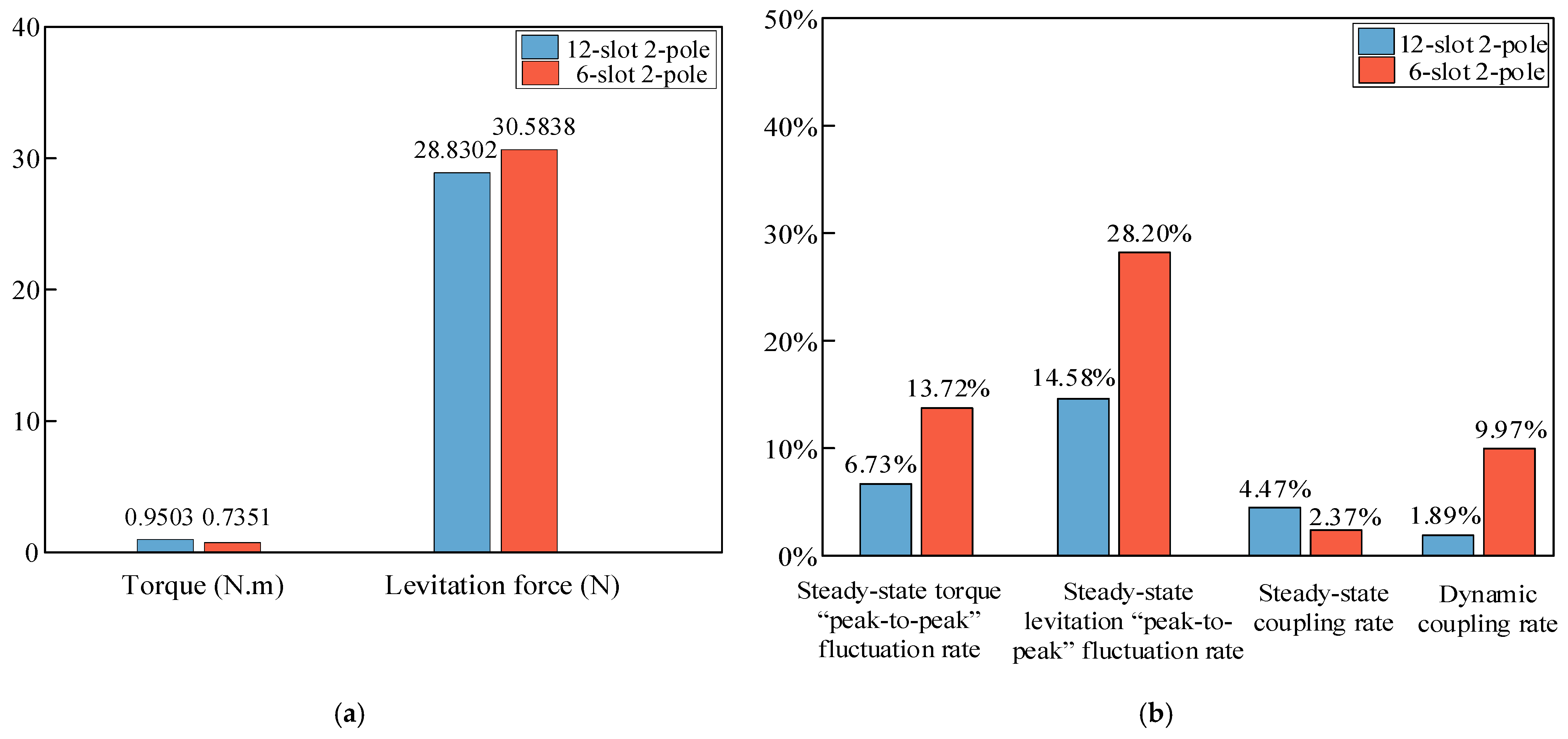
4.3. Comparative Analysis with Six-Phase CSW-6/2-BPMSM

To verify the performance advantages of the six-phase DSW-12/2-BPMSM in terms of the amplitude and fluctuation of electromagnetic torque and radial magnetic levitation force waveforms, as well as the electromagnetic coupling rate between them, a detailed comparison was conducted with a six-phase centralized-winding BPMSM with 6 slots and 2 poles (six-phase CSW-6/2-BPMSM), which is frequently used in the field of low power. Since the slot number of the six-phase CSW-6/2-BPMSM is half of that of the six-phase DSW-12/2-BPMSM, the number of turns for each tooth coil in the CSW-6/2-BPMSM was set to twice that of the six-phase DSW-12/2-BPMSM. The selected slot type is a flat-bottomed groove with a larger area, and the other parameters are the same as those of the six-phase DSW-12/2-BPMSM.
In the case of zero radial displacement, Figure 13 gives the dynamic waveforms of the torque and radial magnetic levitation force in the y-axis direction when a 4.5 A torque current and a 1.0 A levitation current are applied to the stator winding of the six-phase CSW-6/2-BPMSM. Based on Figure 13, combined with Figure 6, Figure 7, Figure 8 and Figure 9, the following comparison result were obtained:
(1) When a 4.5 A torque current is applied, the average torque of the six-phase CSW-6/2-BPMSM is 0.7351 N·m, and the peak-to-peak fluctuation rate is about 13.72%, while the average torque of the six-phase DSW-12/2-BPMSM is 0.9503 N·m, and the peak-to-peak fluctuation rate is about 6.73% (refer to Figure 6). Thus, compared with the commonly used six-phase CSW-6/2-BPMSM, the generated torque of the six-phase DSW-12/2-BPMSM increased by 0.2152 N·m, i.e., the steady-state torque generated by the unit torque current of the six-phase DSW-12/2-BPMSM increased by 0.0478 N·m (about 22.63%). At the same time, the torque pulsation rate was reduced by about 6.99%.
(2) When a 1.0A levitation current is fed, the average value of the radial magnetic levitation force of the six-phase CSW-6/2-BPMSM is 30.5838 N, and the peak-to-peak fluctuation rate of the magnetic levitation force waveform is about 28.2%. Meanwhile, the average value of the radial magnetic levitation force of the six-phase DSW-12/2-BPMSM is 28.8302 N, and the peak-to-peak fluctuation rate is about 14.58% (refer to Figure 8). Therefore, compared with the commonly used six-phase CSW-6/2-BPMSM, the average value of the magnetic levitation force per unit of levitation current of the six-phase DSW-12/2-BPMSM reduced by 1.7536N (about 5.73%). However, the main advantage of the six-phase DSW-12/2-BPMSM is that the peak-to-peak pulsation rate of the radial magnetic levitation force is reduced by about 13.62%, which is more conducive to the stable levitation control of the bearingless rotor.
In order to verify the electromagnetic coupling situation inside the six-phase DSW-12/2-BPMSM, the levitation current was kept at 1A, and the torque current was set to vary in the range of zero to 6A. Figure 14 and Figure 15 show the dynamic waveforms of the magnetic levitation force of the six-phase CSW-6/2-BPMSM and the six-phase DSW-12/2-BPMSM, respectively. Under the same excitation conditions, including zero eccentric displacement, 4.5 A torque current, and 1 A levitation current, Figure 16 shows a comprehensive numerical comparison between the six-phase DSW-12/2-BPMSM and the six-phase CSW-6/2-BPMSM in terms of electromagnetic torque, radial magnetic levitation force, coupling degree, etc. Here, Figure 16a gives the numerical comparison chart of steady-state torque and radial magnetic levitation force, and Figure 16b gives the numerical comparison charts of the peak-to-peak fluctuation rate for torque and radial magnetic levitation force and that of the coupling degree of the torque current to the magnetic levitation force. Based on Figure 14, Figure 15 and Figure 16, the following research results were obtained:
(1) When the torque current changes, the steady-state mean value of the magnetic levitation force generated by the two six-phase BPMSM structures does not change much. The variation rate of the mean magnetic levitation force value of the six-phase CSW-6/2-BPMSM is 2.37%, which is called the steady-state coupling rate here; the six-phase DSW-12/2-BPMSM has a slightly higher rate of change in the mean value of the magnetic levitation force, but this rate never exceeds 4.47%.
(2) As the torque current increases, the peak-to-peak fluctuation rate of the magnetic levitation force of the six-phase CSW-6/2-BPMSM increases from 28.2% to 41.72%. The fluctuation rate at 4.5 A torque current is about 38.17%, which is an increase of about 9.97%, called the dynamic coupling rate here, compared to that at the torque current of zero. In this work, the peak-to-peak fluctuation rate of the magnetic levitation force of the six-phase DSW-12/2-BPMSM is always within the range of 14.54–16.9%. For example, the fluctuation rate under a 4.5 A torque current is about 16.43%, which represents an increase of about 1.89% compared to the case of zero torque current.
In summary, both motor structures have a certain degree of electromagnetic coupling. For the six-phase DSW-12/2-BPMSM, the steady-state coupling rate of the torque current to the mean value of the magnetic levitation force is slightly higher than that of the commonly used six-phase CSW-6/2-BPMSM. However, the main advantage of the six-phase DSW-12/2-BPMSM is that its dynamic coupling rate of torque current to the radial magnetic levitation force is lower than that of the commonly used six-phase CSW-6/2-BPMSM. Table 2 shows a summary comparison of the electromagnetic and mechanical characteristics between the six-phase DSW-12/2-BPMSM and the commonly used six-phase CSW-6/2-BPMSM.

5. Conclusions

In this work, a six-phase distributed single-winding BPMSM with 12 slots and 2 poles (six-phase DSW-12/2-BPMSM) was proposed and investigated, utilizing the performance advantages of the distributed winding structure. First, the structure of the six-phase DSW-12/2-BPMSM was introduced, as well as its electromagnetic torque and magnetic levitation force control principle. Then, by fully considering the influence of the relative permeability parameter of permanent magnets (i.e., including the relative permeability parameter in the calculation formula of the average equivalent air gap length, g0), accurate modeling of the electromagnetic torque and the radial magnetic levitation force was conducted. This was based on the distribution function method, coordinate transformations, and the principle of imaginary displacement. Finally, FEM validation and analysis of the established mathematical models was carried out using Ansys Maxwell software, and a detailed comparative analysis of the electromagnetic characteristics was performed with the commonly used six-phase CSW-6/2-BPMSM structure. The research conclusions are as follows:
(1) In the case of an unsaturated magnetic circuit of the six-phase DSW-12/2-BPMSM, the electromagnetic torque and controllable magnetic levitation force are proportional to the torque current and levitation current, respectively.
(2) For the six-phase DSW-12/2-BPMSM, the established electromagnetic torque and controllable magnetic levitation force models are effective and have high calculation accuracy. Under the setting conditions of the motor structure parameter in this work, the maximum calculation error of the torque model did not exceed 6.86%, while the maximum calculation errors of the controllable magnetic levitation force model and the eccentric magnetic pull force model did not exceed 0.25% and 6.4%, respectively. The maximum calculation errors were all within the acceptable range. The reasons for the errors include the following: firstly, in terms of material properties, the influences of magnetic circuit nonlinearity and the harmonic magnetic field were not sufficiently considered; secondly, although the main geometrical structure was considered in the modeling, the simplified treatment of some details will lead to errors. In order to improve the model’s accuracy, the material properties and nonlinear modeling will be further optimized subsequently.
(3) The six-phase DSW-12/2-BPMSM is a single-winding BPMSM structure well suited for low-power applications. Compared to the traditional six-phase CSW-6/2-BPMSM structure with centralized windings, the steady-state magnetic levitation force control stiffness of the researched six-phase DSW-12/2-BPMSM is slightly lower. However, the six-phase DSW-12/2-BPMSM adopts a distributed single-winding structure, which is able to reduce the influence of harmonics, allowing it to obtain better control characteristics in terms of torque and levitation force. The six-phase DSW-12/2-BPMSM has relatively large torque control stiffness, and its dynamic torque waveform over time is relatively smooth; moreover, the peak-to-peak pulsation rate of its magnetic levitation force waveform and its coupling effect of torque current with the radial magnetic levitation force are both acceptable. These advantages highlight the good application prospects of the six-phase DSW-12/2-BPMSM structure proposed in this work in the low-power field.
The six-phase DSW-12/2-BPMSM structure studied in this work, as well as the accurate analytical modeling method that considers the influence of the relative permeability of permanent magnets, offers a new approach for the structural optimization of low-power single-winding BPMSMs and provides a theoretical basis for the design of their high-performance control systems.

Author Contributions

Conceptualization, W.B.; Methodology, Y.L. and J.L.; Investigation, Y.L.; Validation, J.L.; Resources, W.B.; Data curation, J.L.; Writing—original draft, Y.L.; Writing—review & editing, J.L. and W.B.; Visualization, J.L.; Supervision, W.B. All authors have read and agreed to the published version of the manuscript.

Funding

This research was funded by the Key scientific and technological project in Henan province, grant number 202102210095.

Institutional Review Board Statement

Not applicable.

Informed Consent Statement

Not applicable.

Data Availability Statement

The original contributions presented in the study are included in the article, further inquiries can be directed to the corresponding authors.

Acknowledgments

We are grateful to Henan University of Science and Technology for providing the facilities for us to carry out this study.

Conflicts of Interest

The authors declare no conflicts of interest.

References

  1. Hu, Y.F.; Taha, O.W.; Yang, K. Fault Detection in Active Magnetic Bearings Using Digital Twin Technology. Appl. Sci. 2024, 14, 1384. [Google Scholar] [CrossRef]
  2. Chen, J.H.; Zhu, J.W.; Eric, L. Review of bearingless motor technology for significant power applications. IEEE Trans. Ind. Appl. 2020, 56, 1377–1388. [Google Scholar] [CrossRef]
  3. Sun, C.; Yang, Z.B.; Sun, X.D.; Ding, Q.F. An Improved Mathematical Model for Speed Sensorless Control of Fixed Pole Bearingless Induction Motor. IEEE Trans. Ind. Electron. 2024, 71, 1286–1295. [Google Scholar] [CrossRef]
  4. Shen, H.; Bian, F.; Yue, Y.; Li, B.; Yu, P.; Yang, L.; Chen, G.; Hu, L. Multi-Structural Optimization of Bearingless Permanent Magnet Slice Motor Based on Virtual Prototype in Ansoft Maxwell. Appl. Sci. 2021, 11, 4740. [Google Scholar] [CrossRef]
  5. Bu, W.S.; Wan, S.M.; Huang, S.H.; Liu, W.S. General Analytical Model About Controllable Magnetic Suspension Force of Bearingless Motor. Proc. CSEE 2009, 29, 84–89. [Google Scholar]
  6. Bao, X.C.; Wang, X.L.; Ding, Q.; Shi, T.R. Design of Double Staggered Parallel Bearingless Motor Drive System. IEEE Trans. Power Electron. 2023, 38, 2230–2239. [Google Scholar] [CrossRef]
  7. Rao, P.N.; Kumar, N.M.; Padmanaban, S.; Subathra, M.S.P.; Chand, A.A. A Novel Sensorless Approach for Speed and Displacement Control of Bearingless Switched Reluctance Motor. Appl. Sci. 2020, 10, 4070. [Google Scholar] [CrossRef]
  8. Xu, K.; Guo, Y.G.; Lei, G.; Sun, X.D.; Zhu, J.G. Electromagnetic Performance Analysis of a Bearingless Permanent Magnet Synchronous Motor by Model Order Reduction. IEEE Trans. Magn. 2023, 59, 11. [Google Scholar] [CrossRef]
  9. Bu, W.S.; Li, H. Torque System Modeling and Electromagnetic Coupling Characteristics Analysis of a Midpoint Injection Type Bearingless Permanent Synchronous Magnet Motor. Int. Trans. Electr. Energy Syst. 2024, 2024, 3078894. [Google Scholar] [CrossRef]
  10. Khoo, W.K.S.; Kalita, K.; Garvey, S.D. Practical implementation of the bridge configured winding for producing controllable transverse forces in electrical machines. IEEE Trans. Magn. 2011, 47, 1712–1718. [Google Scholar] [CrossRef]
  11. Petersen, N.; Khamitov, A.; Slininger, T.; Severson, E.L. Machine Design and Precision Current Regulation for the Parallel DPNV Bearingless Motor Winding. IEEE Trans. Ind. Appl. 2021, 57, 7000–7001. [Google Scholar] [CrossRef]
  12. Li, B.N.; Huang, J.; Kang, M.; Kong, W.B. Analysis and Comparison of Inductance and Suspension Force for 2-4 Type and 4-2 Type Multiphase Permanent Magnet Bearingless Motors. Proc. CSEE 2013, 33, 106–114. [Google Scholar]
  13. Yuan, J.F.; Zhu, H.Q.; Zhao, Y.L.; Ding, Q. Structure principle and control of novel dual three-phase bearingless permanent magnet synchronous motor. Adv. Technol. Electr. Eng. Energy 2017, 36, 16–24. [Google Scholar]
  14. Wang, X.L.; Sheng, W.; Deng, Z.Q.; Ren, X.Y. Operating Characteristics Analysis of Multi-phase Bearingless Permanent Magnet Slice Motors with Faulty Phases. Proc. CSEE 2011, 31, 73–78. [Google Scholar]
  15. Dietz, D.; Messager, G.; Binder, A. 1kW/60,000min (-1) bearingless PM motor with combined winding for torque and rotor suspension. Iet Electr. Power Appl. 2018, 12, 1090–1097. [Google Scholar] [CrossRef]
  16. Qin, Y.M.; Zhu, H.Q. Torque and Suspension Force Optimization for Five-phase Bearingless PMSM with Third-order Harmonic Injection. Proc. CSEE 2018, 38, 6701–6710. [Google Scholar]
  17. Faiz, J.; Tabatabaei, I. Extension of winding function theory for nonuniform air gap in electric machinery. IEEE Trans. Magn. 2002, 38, 3654–3657. [Google Scholar] [CrossRef]
  18. Wang, H.M.; Bai, H.J.; Guo, L.Y. Design of Single-Winding Arrangement for Arbitrary Multiphase Bearingless Permanent Magnet Synchronous Motor. J. Electr. Eng. Technol. 2024, 1–11. [Google Scholar] [CrossRef]
Figure 1. Structural diagram of the six-phase DSW-12/2-BPMSM.
Applsci 15 02093 g001
Figure 2. Unfolding diagram of the six-phase DSW-12/2-BPMSM winding.
Applsci 15 02093 g002
Figure 3. Magnetic levitation force generation principal diagram.
Applsci 15 02093 g003
Figure 4. Schematic diagram of rotor eccentricity.
Applsci 15 02093 g004
Figure 5. Distribution of magnetic lines of force after applying levitation current.
Applsci 15 02093 g005
Figure 6. Torque waveform when the torque current changes.
Applsci 15 02093 g006
Figure 7. Curve of torque variation with torque current.
Applsci 15 02093 g007
Figure 8. Dynamic waveform of radial magnetic levitation force with variation in the levitation current.
Applsci 15 02093 g008
Figure 9. Variation curve of radial magnetic levitation force with levitation current.
Applsci 15 02093 g009
Figure 10. Eccentric magnetic pull waveform at static eccentricity.
Applsci 15 02093 g010
Figure 11. Variation curve of eccentric magnetic tension with static eccentric displacement.
Applsci 15 02093 g011
Figure 12. Eccentric magnetic pull waveform during dynamic eccentricity.
Applsci 15 02093 g012
Figure 13. Torque and magnetic levitation force waveforms of the six-phase CSW-6/2-BPMSM used for comparison.
Applsci 15 02093 g013
Figure 14. Magnetic levitation force waveform of the six-phase CSW-6/2-BPMSM under different torque currents.
Applsci 15 02093 g014
Figure 15. Magnetic levitation force waveform of the six-phase DSW-12/2-BPMSM under different torque currents.
Applsci 15 02093 g015
Figure 16. Comparison chart of numerical values after comprehensive processing: (a) steady-state numerical value comparison of torque and magnetic levitation force; (b) numerical comparison of fluctuation rate and coupling rate.
Applsci 15 02093 g016
Table 1. Main parameters of the six-phase DSW-12/2-BPMSM.
ParameterValue
Pole-pair number of the rotor1
Number of stator slots12
Stator core outer diameter (mm)80
Stator core inner diameter (mm)38
Rotor core outer diameter (mm)32
Thickness of PM, Lm (mm)2
Air gap length, g (mm)1
L1 (mH)5.45
L2 (mH)2.72
M12 (H/m)0.6829
Ψf (Wb)0.133
Axial length (mm)40
Residual magnetic density of PM (T)1.23
Coercivity of PM (kA/M)−890
Turn number of coils100
Core materials of stator and rotor DW465_50
Permanent magnet materialsNdFe35
Relative permeability, μr1.09978
Boundary conditionNatural boundary condition
Rated power (kw)1.2
Rated speed (rpm)3000
Table 2. Comparative summary of characteristics between the two BPMSM structures.
Characteristics/
Performance
Six-Phase CSW-6/2-BPMSMSix-Phase DSW-12/2-BPMSM
Mechanical structureSimpleModerate
Harmonic contentHighLow
Torque stiffnessModerateHigh
Suspension force stiffnessModerateModerate
Torque pulsationModerateSmall
Suspension force pulsationLargeModerate
CouplingModerateLow
EfficiencyModerateHigher
NoiseObviousModerate
Field of applicationLow powerLow power
Disclaimer/Publisher’s Note: The statements, opinions and data contained in all publications are solely those of the individual author(s) and contributor(s) and not of MDPI and/or the editor(s). MDPI and/or the editor(s) disclaim responsibility for any injury to people or property resulting from any ideas, methods, instructions or products referred to in the content.

