Article

Analysis of Strength Effects on the Dynamic Response of a Shaped-Charge Under Lateral Disturbances

1
College of Electromechanical Engineering, North University of China, Taiyuan 030051, China
2
Anhui Dongfeng Mechanical and Electrical Technology Co., Ltd., Hefei 231202, China
*
Author to whom correspondence should be addressed.
Appl. Sci. 2025, 15(11), 6313; https://doi.org/10.3390/app15116313
Submission received: 10 April 2025 / Revised: 23 May 2025 / Accepted: 29 May 2025 / Published: 4 June 2025
(This article belongs to the Special Issue Nonlinear Dynamics in Mechanical Engineering and Thermal Engineering)

Abstract

:
To study the variation law of the penetration power of energy-concentrated jets on target plates with different yield strengths under lateral disturbance, a finite element model of the dynamic penetration of energy-concentrated jets was established. Targets with different yield strengths (355 MPa–1275 MPa) were analyzed under conditions from low speed (100 m/s) to high speed (400 m/s). The dynamic penetration morphology of the jet, the dynamic failure mode of the target plate and the dynamic penetration depth of the jet were analyzed. The influence law of the target plate strength on the dynamic penetration of the jet was analyzed by introducing the offset angle as a parameter and combining it with the dynamic penetration depth of the jet. Based on dimensional analysis, a prediction model for the dynamic penetration performance of the jet that considered both the lateral disturbance velocity and the strength of the target plate was obtained. A test of the dynamic penetration of the jet based on the rocket trolley was designed and carried out. Experiments were conducted to determine the dynamic penetration of the jet through target plates with different yield strengths under different lateral disturbance velocities, and the corresponding data were obtained. The reliability of the numerical simulation and of the prediction models was verified. The research results show that the jet offset angle under different yield strengths increases with the increase of the lateral disturbance velocity. When the lateral disturbance velocity is held constant, the size of the offset angle is negatively correlated with the yield strength of the target plate. The results of the prediction model, numerical simulation and dynamic penetration test were compared and verified. It was found that the three showed good consistency and that the prediction model could estimate the dynamic penetration depth of the jet with respect to the strength of the target plate.

1. Introduction

Based on the cumulative effect, the shaped-charge jet is driven by the high energy of the explosive, which causes the horn-shaped thin-walled metal liner to collapse, converge and elongate along its axis [1,2]. Despite extensive utilization in terminal ballistics systems, the pseudoviscous flow dynamics exhibited by shaped-charge jets under high-strain-rate loading regimes engender complex multiscale phenomena at the solid-fluid interface, presenting theoretical and computational challenges distinct from those addressed in classical elastoplastic solid mechanics frameworks [3,4,5,6,7]. Despite widespread application, shaped-charge jets exhibit fluid-like behaviors under ultrahigh-strain-rate conditions, presenting continuum mechanics complexities fundamentally distinct from those addressed by classical solid mechanics frameworks. When subjected to lateral disturbances, these jets display fluid-like behavior characterized by dynamic buckling instabilities and shear-localization mechanisms. This study investigates the structural integrity of shaped-charge jets during off-axis penetration by analyzing the dynamic coupling between jet–target interactions and the resistance characteristics of the target. Empirical observations confirm that lateral perturbations elicit extremely dense fluid like flow behaviorin shaped-charge jets. The jet–target interaction generates multiaxial stress regimes (axial compression/transverse shear superposition), initiating material failure in three stages: viscous flow deformation, dynamic compressive buckling and ductile crack propagation.
The dynamic impact process of a shaped-charge jet under lateral disturbance has also been studied by many scholars. Li et al. [8] investigated the effect of the carrier’s initial velocity on the jet’s power to inflict damage. In that study, the ratio of oblique to normal penetration depth for a jet with varying following velocities was derived based on the theory of steady jets and hole expansion, and its accuracy was verified. Held [9] conducted a preliminary exploration of the impact of a shaped-charge jet on moving targets using experiments; Frankel et al. [10] studied glancing impacts resulting from non-parallel orientation between the target velocity and the projectile. The effect of the transverse motion of the target on penetration performance was analyzed by means of a hydrodynamic model. Walters et al. [11] systematically studied the formation, penetration mechanisms and applications of shaped charges. Golesworthy [12] has studied the penetration performance of shaped-charge jets, emphasizing that lateral velocity leads to jet bending and fracture, which greatly reduces penetration performance. Jia et al. [13] conducted work based on virtual origin theory, carrying out a detailed theoretical analysis for each stage and establishing theoretical algorithms to describe the cavity evolution that occurs when a shaped-charge jet penetrates a thick moving target, the penetration depth of the undisturbed jet, the lateral velocity of the jet and the penetration depth contributed by the disturbed jet. Dorogoy et al. [14] considered the effect of the target’s motion during penetration and studied the effects of glancing collisions in which the speeds of both participants are of the same order of magnitude and are not collinear. Kobylkin et al. [15] studied the steady and unsteady interaction mechanisms between a shaped-charge jet and the forward (moving in the direction of the jet) and rear (moving in the direction opposite the jet) plates. Li et al. [16] established a compressible model of a shaped-charge jet penetrating with radial reaming, and Held and Fischer [17] investigated the main factors affecting jet penetration into a thin moving target. Han [18] numerically simulated the impact of a shaped-charge jet on a moving target plate at different incident angles and identified the fundamental laws governing the penetration performance of the shaped-charge jet following an oblique impact.
Scholars have also conducted some research into dynamic penetration under lateral disturbance [19,20,21,22]. However, practical experiments introducing high lateral-disturbance velocities are rarely published. In particular, there has been little work focused on analyzing the influence of different target intensities on the dynamic penetration velocity of the jet, which is most often obtained through numerical simulation and theoretical derivation. In order to systematically analyze the process of the jet penetration into targets with varying yield strengths, we conducted numerical simulations of the process of the jet penetration. We introduced variables such as deflection angle and resistance duration to quantify the effect of target strength. We designed and conducted dynamic jet-impact tests with different lateral disturbance velocities and target intensities to observe the dynamic response behavior of the jet under these special crossing conditions.
Based on actual experimental results, we verified the effectiveness and accuracy of the numerical simulations. Afterwards, using the dimensional analysis method, we established an engineering prediction model that accounts for the lateral disturbance velocity and target strength and compared the model’s predictions with dynamic experimental data to verify the applicability and effectiveness of the established engineering prediction model.

2. Finite Element Model and Research Scheme

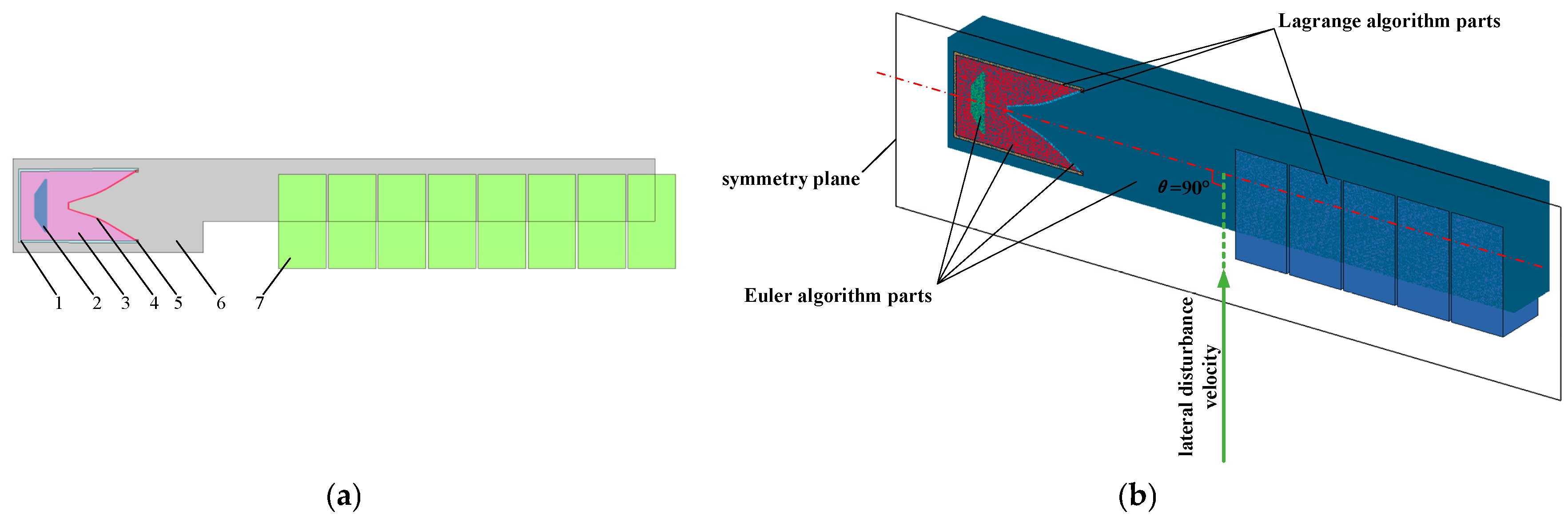
2.1. Simplified and Numerical Simulation Models

This study employs a hybrid Lagrangian–Euler computational framework in which the target plate is modeled using a Lagrangian mesh to track deformation history, while other components are modeled via a Eulerian approach to accommodate extreme material distortions, with fluid-structure interaction (FSI) algorithms simulating the coupled processes of the jet formation and hypervelocity penetration dynamics. This framework enables high-fidelity simulation of both jet formation and penetration dynamics, including material fragmentation and hydrodynamic instabilities. The shaped-charge assembly comprises engineered components including a aluminum alloy shell, an explosive charge, a phenolic resin wave shaper, and a copper liner featuring dual-angle conical geometry. Numerical simulations were performed using a half-symmetry 3D model (1:1 scale) and hexahedral meshes. This approach balances accuracy with resource constraints, which is critical for simulating hypervelocity jet interactions under lateral disturbances.
In order to simulate the propagation of explosives in real world scenarios, taking into account the process of shaped-charge jet formation and the compression mechanism of the detonation wave on the liner, the air region is maintained in the area where the charge acts on the liner, and the non-reflective boundary is applied to the outer surface of the air region in the finite element model to allow explosive gases to exit freely. This setup is used to reduce the calculation time needed for the numerical simulation while maintaining the accuracy of calculation. Due to the large deformation and high strain-rate characteristics of a shaped-charge jet, a smaller time step of 0.35 μs was set in the numerical simulation. Figure 1a is the numerical simulation model of the jet’s dynamic penetration. The explosive height of the shaped-charge warhead is 175 mm, and the element size in the air domain is 1 mm × 1 mm × 1.5 mm. Based on experimental conditions, the structure of the target plate in the numerical simulation is modeled with a homogeneous plate of 60 mm thickness and an element size of 1 mm × 1 mm × 1 mm.
We used a single precision LS-DYNA finite element solver for numerical simulation. In the numerical simulations, each group uses the same grid size, component size, etc., with variations tested only for the target lateral disturbance velocity and target material. Therefore, for all numerical simulations, the nodes and elements remained consistent. Each group of numerical simulations used 1,107,037 elements and 1,474,284 nodes.
Figure 1b shows the use of the Euler algorithm to simulate the large-strain behavior of the air domain, liner and explosive; the Lagrangian algorithm was used to simulate the deformation, failure and other characteristics of the metal shell and target plate.
We adopted the Structured ALE(S-ALE) algorithm and the Lagrangian algorithm to perform coupled calculations for fluid–structure interactions in this study. By employing the *INITIAL_VOLUME_FRACTION_GEOMETRY keyword in the LS-DYNA solver, we were able to model the liner, charge and wave shaper as shell element containers with the appropriate dimensions and geometric shapes. Using this keyword, the S-ALE algorithm generated the liner, charge and wave shaper in the air domain with the corresponding geometric dimensions and materials.
For the shell, ring and target plate, TrueGrid was adopted for hexahedral mesh modeling, with the components defined per the Lagrangian algorithm in LS-DYNA. Throughout the entire numerical simulation, all of the parts of the Lagrangian algorithm were coupled with all of the parts of the S-ALE algorithm, thereby effectively simulating the interaction between the shaped-charge warhead and the solid target plate under conditions of large deformation.
LS-DYNA (ver. R971) finite element analysis software was used for fluid–structure interaction analysis. In the numerical simulation, there was always a velocity (lateral disturbance velocity) perpendicular to the axis of the shaped-charge jet on the target plate, and this velocity was used to analyze the dynamic response characteristics and variation law of the shaped-charge jet under transverse disturbance.

2.2. Material Model and Parameters

The liner material was modeled using the Johnson–Cook material model and the Grüneisen equation of state [23]. The material model and equation of state can be used to effectively characterize the mechanical behavior of the material under high strain-rate conditions, so it could be used to simulate the mechanical behavior of the liner in this study. The parameters are shown in Table 1.
The high-explosive-burn model is a standard constitutive model used to simulate the behavior of high explosives. This model describes the process by which explosive materials transform into detonation products and is usually used in combination with an equation of state such as the Jones–Wilkins–Lee equation. The material parameters and equation of state are derived from Reference [24], as follows:
P = A 1 ω R 1 V e R 1 V + B 1 ω R 2 V e R 2 V + ω E 0 V
where P is the isentropic pressure; V is the relative volume of detonation products; and E0 is the initial internal energy. The relevant parameters are shown in Table 2.
Here, D represents the detonation velocity of the charge and Pcj represents the C–J explosive pressure of the charge. The shell and the retaining ring were made of aluminum alloy, and the explosive and the liner were tightly fixed together via the retaining ring. The target materials were 603# steel, 35CrMnSiA and 45# steel. The wave shaper was made of phenolic resin. The shell, ring, wave shaper and target are all described by the Plastic–Kinematic model, an elastic–plastic material model that is strain-rate dependent and includes failure criteria [7]. The material parameters of the shell, wave shaper and target plate are shown in Table 3. The material parameters are based on values from the literature [7,25,26,27,28].
Here, E is Young’s modulus, v is Poisson’s ratio, and σY is the yield stress of the material. For phenolic resin, 603# steel, 35CrMnSiA and 45# steel, isotropic hardening (β = 1) was adopted, while mixed hardening (β = 0.5) was used for the aluminum alloy.

3. Dynamic Impact Process of the Jet Under the Influence of Target Strength

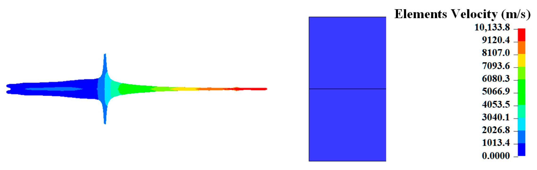
3.1. Typical Jet Dynamic Impact Process

Figure 2 presents a diagram showing the shape and velocity cloud of the jet before it penetrates the stationary target plate. It can be seen that the head velocity of this type of energy-concentrated jet can reach 10,133.8 m/s before it hits the target.
In order to analyze the evolution of the dynamic impact of the jet on target plates with different material strengths, dynamic impact processes of the jet with lateral disturbance velocities in the range 100–400 m/s were numerically simulated. Representative results are shown in Figure 3.
As the lateral disturbance velocity increases, the impact depth of the jet decreases continuously. When the lateral disturbance velocity vt = 100 m·s−1, the disturbance effect of the target plate on the impact of the jet is relatively weak, but the tail jet and the pestle are disturbed by the target plate and cannot flow into the jet channel normally. At the surface of the first target plate, the jet flows into the jet channel after colliding and interacting with the target plate, leaving a large crater on the target surface. This leads to the bending and breaking of the jet in the impact channel before the impact has had its full effect, and to interaction with the crater wall, which reduces the impact depth. The damage to the first layer of the target plate increases significantly with increased lateral disturbance velocity, as does the damage does by the cutting-like effect in the direction of the target plate’s motion. For the subsequent layers of the target plate, the failure mode in the direction of the target plate’s motion remains relatively unchanged; the primary difference is a change in the penetration depth in the axial direction. For targets with different strengths, the difference in penetration depth in the axial direction is more obvious than the difference in the damage associated with transverse cutting.

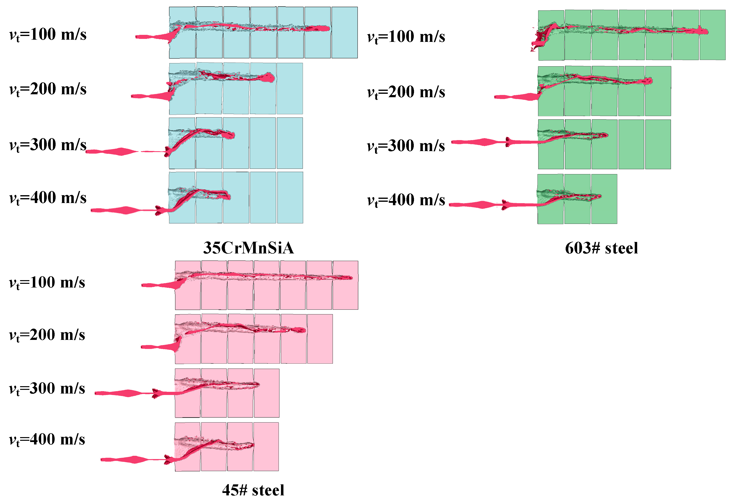
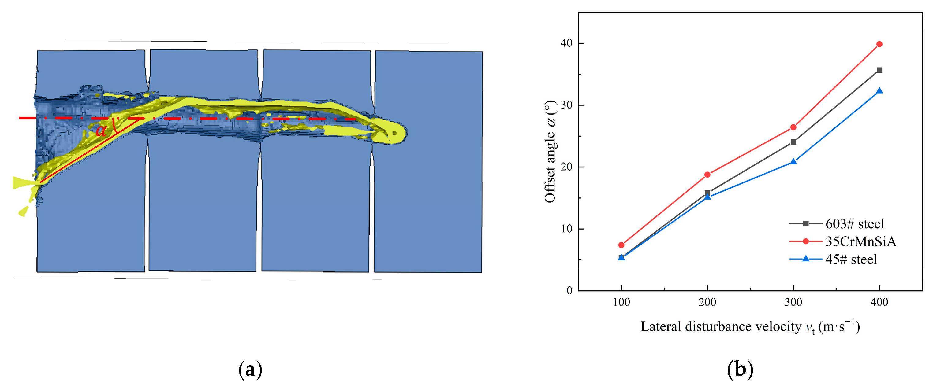
3.2. Analysis of Disturbed Impact Process

In order to analyze the influence of target strength on the dynamic impact process of the jet, the jet offset angle α under different target strengths and different lateral disturbance velocities was extracted.
It can be seen from Figure 4a that in the process of dynamic impact, due to the lateral disturbance of the target plate, the jet inevitably collides with the wall of the channel and then flows to the bottom of the pit at a certain angle along the wall of the channel. In the process of flow, due to the existence of offset angle, if the offset angle is large enough, the jet will collide with the wall of the channel twice, which will greatly weaken the velocity of the jet element and affect its ability to impact the bottom of the jet channel.
From Figure 4b, it can be seen that when the lateral disturbance velocity increases, the offset angle of the jet during dynamic impact with the target plates with different yield strengths increases continuously. Moreover, for target plates with larger yield strengths, the offset angle of the jet is also larger. When the lateral disturbance velocity is low, the differences in the jet offset angle under different target strengths are small. This is because when the lateral disturbance is low, the impact of the target plate on the jet is weak, and the energy loss experienced by the jet after the collision is small. It can continue to flow and complete the impact at the bottom of the channel. As the lateral disturbance velocity increases gradually, the differences among the jet offset angles under different target strengths begin to appear. When the jet penetrates a target plate with a smaller yield strength, its resistance is also stronger, so the offset angle is also smaller.
The depth of the jet’s dynamic impact under different target strengths is calculated, as shown in Figure 5.
It can be seen from Figure 5 that the impact depth of the jet decreases with increasing lateral disturbance velocity. With the increase in the lateral disturbance velocity, the difference between target plates with different yield strengths gradually decreases. This is mainly because the existence of the transverse disturbance makes it possible to smoothly enter the bottom of the target plate channel, and the result is progressively reduced jet penetration into the crater. Only the jet element at the head can effectively play a role, as this part of the jet element has higher speed and carries more energy. Its interaction with the target plate is the initial stage of jet impact. At this time, the influence of the target plate strength can almost be ignored during penetration, while subsequent jet elements are affected by the transverse disturbance and cannot make an effective contribution to the jet impact depth.

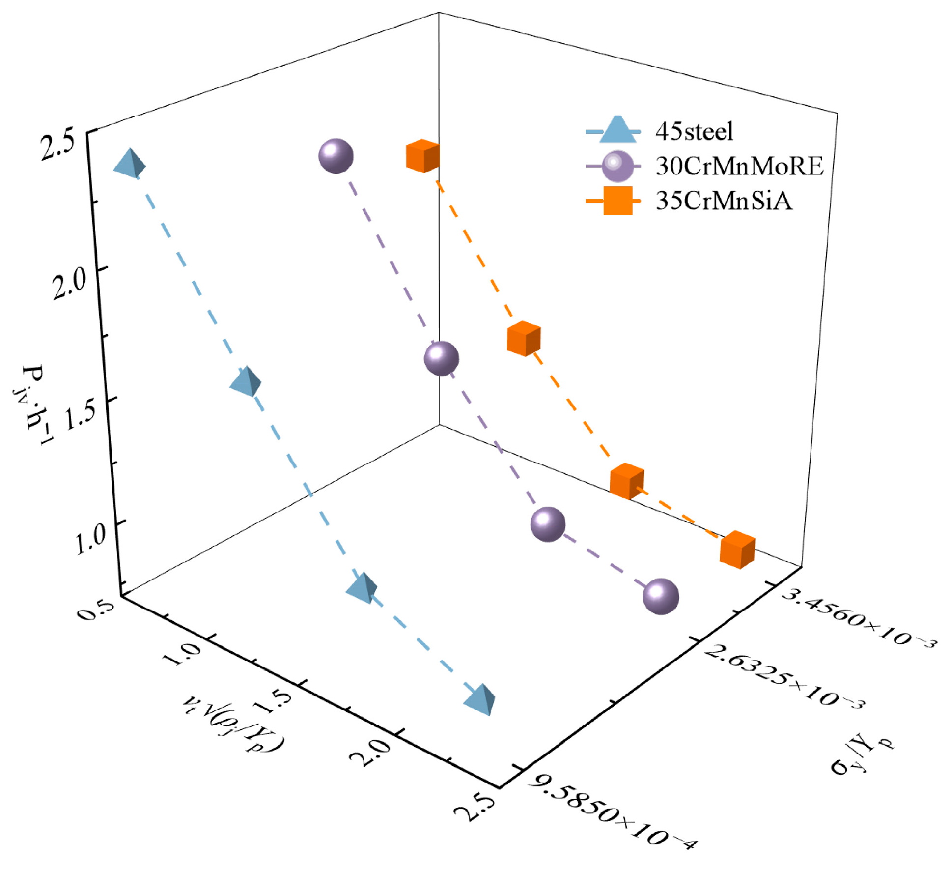
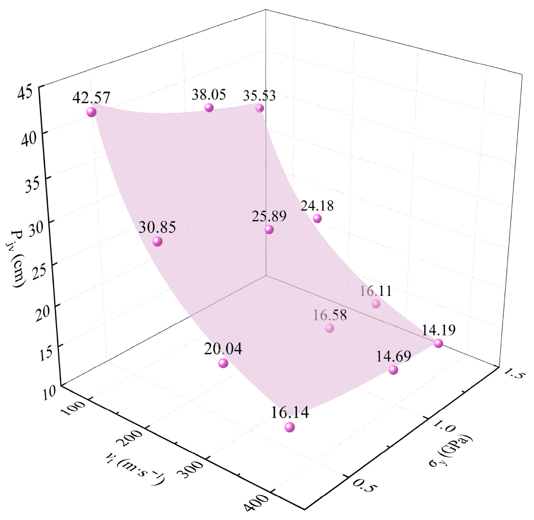
3.3. Establishment of Prediction Model

Dimensional analysis is an effective tool through which to solve contemporary engineering problems, and it has a wide range of applications. Usually, although the same physical quantity can be expressed in different units, its dimension is fixed. Physical quantities have dimensional properties, so it is necessary to ensure that the dimensions on both sides of the equation are consistent when using mathematical formulas to describe the potential laws governing the corresponding problems. This principle is called the principle of dimensional consistency. Based on the principle of dimensional consistency, the relationship between physical quantities in the research problem can be subjected to dimensional analysis.
Wang et al. [28] conducted research on the dynamic impact behavior response of the jet by using dimensional analysis but did not focus on considering the influence of the target plate strength on the dynamic penetration depth of the jet. In their approach to analyzing the dynamic impact behavior response problem of shaped charges, especially when considering the simultaneous influence of the lateral disturbance velocity and the target plate strength on the dynamic penetration depth of the jet, the physical quantities influencing the results were examined using dimensional analysis. For the analysis of the conditions examined in this paper, the charge composition remains constant under different working conditions. Therefore, factors such as charge density, charge detonation velocity and charge energy density can be ignored. Due to the complexity of the dynamic impact process of the jet, the density and strength of the jet and the target material play important roles and cannot be ignored. Therefore, the liner height l, caliber ϕ, liner thickness ξ, cone angle θ, charge length L, standoff height h, jet density ρj, target plate density ρt, target plate elastic modulus Ety, liner yield strength Yp, target plate yield strength Yt, target plate hardening modulus Eth, target plate ultimate strength Yts, target plate failure strain εfs, and target lateral velocity vt were selected for analysis. μp and μt represent the Poisson’s ratio of the liner material and the Poisson’s ratio of the target material, respectively.
This study focused only on metallic materials and does not cover non-metallic materials. As this paper focused on the influence of relative velocity vt on the jet impact depth, the target materials used were the same, so the elastic modulus, density and Poisson’s ratio of the different targets are very similar and the influence of ρt, Ety and μt can be ignored. For the same material liner, the material Poisson’s ratio μp is consistent. Therefore, after simplification, the dynamic penetration depth of shaped-charge jet Pj,dyn was obtained as follows:
P j , dyn = f ( l , ϕ , ξ , L , ρ j , h , Y p , Y t , E th , Y ts , θ , ε fs , v t )
The jet yield strength Yp, the standoff h and the jet density ρj were selected as the reference physical quantities. The determinant was not zero, and the dimensions of the three reference quantities were independent, indicating that any one of the reference quantities could not be represented by the other two reference quantities, so the three reference quantities could be used as a set of basic quantities. This means that the remaining physical quantities could be obtained by linear transformation of the reference physical quantities.
In the Plastic–Kinematic model, the Cowper–Symonds model has good effectiveness. In this model, the dynamic yield strength σy; the strain rate ε ˙ ; the hardening parameter β and the plastic hardening modulus Ep are determined by the elastic modulus Ety and the hardening modulus Eth.
Thus, it can be found from Equation (2) that the peak value of dynamic yield strength considering strain rate is related to yield strength, hardening modulus and failure strain.
In this paper, the liner height l, caliber ϕ, liner thickness ξ, cone angle θ and charge length L were not changed. Therefore, by incorporating the Cowper–Symonds model, after dimensional analysis, the expression of the dimensionless parameter Pj,dyn/l was obtained as follows:
P j , dyn l = f ( v t ρ j Y p , σ y Y p , ε fs )
In order to analyze the influence of each variable on the dynamic impact performance of the jet, the relationship between the dimensionless variable Pj,dyn/l and vt√(ρj/Yp), obtained by numerical simulation, is illustrated in Figure 6.
The findings show that there is a strong exponential relationship between Pj,dyn/l and various factors. Therefore, the variables are coupled in exponential form. Applying the Π theorem, let Equation (4) be transformed as follows:
P j , dyn l = χ v t ρ j Y p a σ y Y p b ε fs c
where a, b and c are undetermined exponential coefficient terms. In order to determine the value of the undetermined coefficients in the above expression, the simulation data results were statistically analyzed. The results of the fitted functional relationship are as follows:
P j , dyn l = 1.213 v t ρ j Y p 0.668 σ y Y p 0.147 ε fs 2.948
Based on Equation (5), the results of the numerical simulation of dynamic penetration by a shaped-charge jet are compared with the dimensional analysis results, as shown in Figure 7.
It can be seen from Figure 7 that the dynamic penetration depth of the jet shows a negative correlation with both the strength of the target plate and the lateral disturbance velocity. The surfaces in the Figure 7 represent the predicted values of the established dimensional analysis model; the scattered points are the original results of the numerical simulations; and the surfaces represent the predicted results of the established dimensional model.
The R2 value of the equation is 0.946, and the expression obtained by dimensional analysis is in good agreement with the numerical simulation results, and has high consistency with the numerical simulation results. At the same time, the prediction model has a good characterization of the effects of lateral disturbance velocity and target strength on jet dynamic penetration.
Combined with the dimensional analysis model, it can be seen that with the increase of the lateral disturbance velocity, the penetration depth of the jet presents an exponential downward trend, which is highly consistent with the conclusion given in the existing relevant literature [7]; For targets with different intensities, the penetration depth under the same lateral disturbance is inversely proportional to the target intensity. Compared with the lower lateral disturbance velocity, the difference of the impact of different target intensities on the dynamic penetration depth of the jet is significantly higher than that of the higher lateral disturbance velocity, that is, compared with the target intensity, the lateral disturbance velocity has a greater impact on the dynamic penetration depth of the jet.

4. Dynamic Impact Test of Shaped-Charge Jet

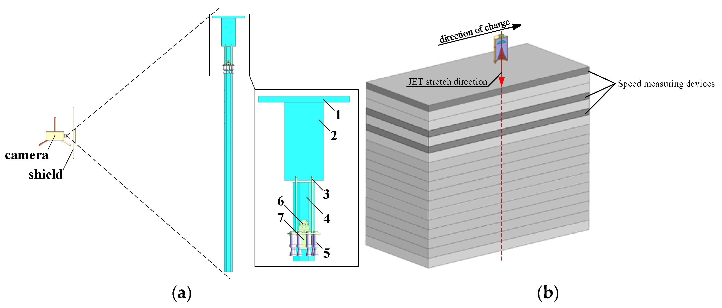
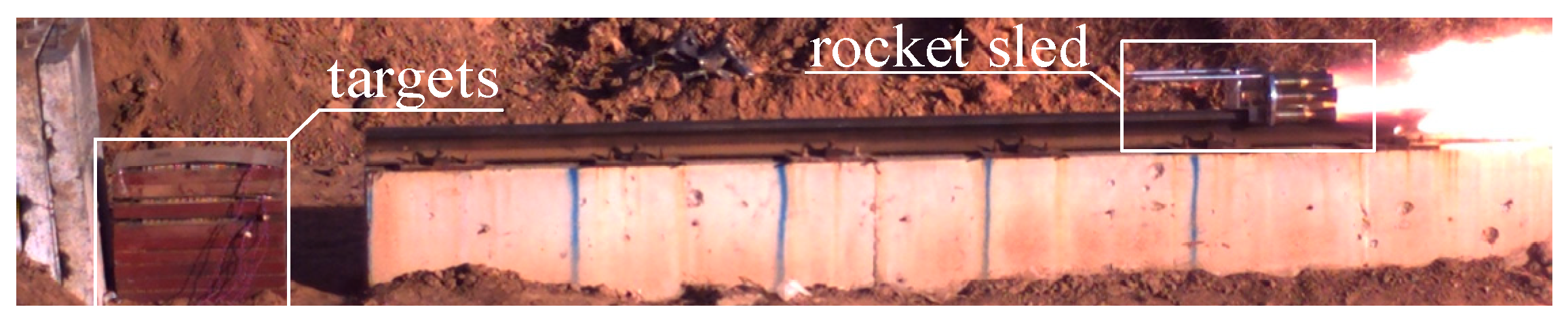
4.1. Dynamic Impact Test Principle

In order to maximize the transverse disturbance velocity, in the experiment conducted in this paper, through the relative motion method, a rocket sled was used to give the shaped jet a transverse motion velocity perpendicular to the penetration direction. Therefore, the speed of the rocket sled corresponds to the lateral disturbance speed in the study.
In order to verify the accuracy of the numerical simulation results and the prediction model, the shaped-charge jet dynamic test system was used for verification analysis. The whole dynamic test system includes a rocket-sled track, pulley, fuze, probe rod, shaped charge, rocket engine, protective device, target plate, test equipment, etc., as shown in Figure 8a. Through the bracket on the pulley, the shaped charge is fixed perpendicular to the track towards the target, and the rocket engine is connected to the pulley. The shaped charge is placed in the front of the pulley. The axial direction of the warhead is perpendicular to the direction of movement of the rocket pulley. The rocket engine is used to push the warhead forward. The pulley accelerates to the predetermined speed and then flies out of the track. There is a probe rod in the front of the pulley, and a collision fuse switch is set at the end of the probe rod. When the fuse hits the end baffle of the track, the electric signal is transmitted to the fuse on the warhead through the internal line of the probe rod, so that the shaped charge is detonated, forming a shaped jet that will hit the horizontally placed target plate. A diagram illustrating the dynamic test is shown in Figure 8b.
The target includes a target plate and a velocity-measuring target. The target is composed of a stack of multiple 60 mm thick homogeneous steel targets, and the velocity sensor is placed to record the velocity of the jet on impact with the target plate and the velocity behind the target. A high-speed camera is mounted on the side of the slide rail, with equidistant marks drawn on the base. The speed of the pulley is calculated by combining the frame rate of the high-speed camera and the movement time of the pulley along the marked rocket pulley path.
During the experiment, in order to obtain the data on jet velocity with target plates of different thicknesses, the velocity-measurement targets were placed on the surface of the target plate, 120 mm behind the target and 180 mm behind the target. The speed target is composed of two layers: an electrical signal-trigger device and a fixed-height plate. The two layers of aluminum foil in the electrical signal trigger device are separated by the intermediate insulation layer and then plasticized as a whole. A wire is arranged on the two layers of aluminum foil. When the jet has not passed through the trigger device, the circuit is disconnected. When the jet passes through the trigger device, the jet destroys the insulating layer between the aluminum foil sheets; thus, the two layers of aluminum foils are connected such that the circuit forms a path and outputs an electrical signal. The spacing of the two-layer trigger device is established by the fixed-height plate, and the head velocity of the jet passing through it can be obtained by recording the time difference between the electrical signals triggered by the two layers.
In the dynamic test, 603# steel and 35CrMnSiA were selected as target materials. In order to obtain the dynamic impact data for the jet on target plates with different yield strengths, high-speed photography was used; a photograph from a typical jet dynamic impact test is shown in Figure 9.
To date, we have conducted a total of three dynamic tests under different operating conditions. Regarding the uncertainties in the experimental results, including factors such as track straightness, synchronization among multiple rocket engines, and vibration of shaped charges under high-speed loads, we tried our best to control the influencing factors. These efforts included the following: (1) control of track straightness; the track used for the rocket sled is a single integrated piece without welds or connecting devices in the middle, ensuring the straightness of the track; (2) synchronization among multiple engines; electronic fuses are used to control the synchronization among engines, and high-speed photography records show that in the three dynamic tests, the delay between engines was less than 125 μs; (3) control of high-speed load vibration; the rocket sled was specifically with the multiple rocket engines arranged to minimize its center of gravity, thereby ensuring smooth movement and reducing air resistance.
Due to the uniqueness of this experiment, the pulley, rocket engine, shaped charge, target plate, etc. are all disposable equipment, and each component is customized. Due to limited preparation time and production costs, repeated tests under various operating conditions have not yet been conducted.

4.2. Numerical Simulation and Validity Verification of Prediction Model

It was estimated that the moving speed of the shaped-charge was 275.86 m/s. The target plate material was 35CrMnSiA, and the shaped jet broke through two layers of homogeneous steel targets and finally accumulated on the third-layer target plate, leaving no obvious trace on the back of the third-layer target plate. The total impact depth was 120 mm. In the numerical simulation under the corresponding working conditions, the jet also penetrated the three-layer target plate, and the value for impact depth was in good agreement with that found here. The results of the numerical simulation and the experimental comparison of the jet dynamic impact are shown in Figure 10.
It can be seen from Figure 10 that the penetration failure modes and effects on both the incident surface and the back surface of each layer of target plate were similar between in the numerical simulation and dynamic test. On the first layer of the target, due to the presence of lateral disturbance velocity, there are obvious cutting marks on the surface of the target, which is quite different from the shape created by the jet penetrating the hole under static conditions. On the surface of the first layer of target plate, the length width ratio of the hole opened by the jet is about 1:1.64; on the second and third target layers, the length: width ratios of the holes after jet penetration are about 1.1 and 1.08; these values are close to 1:1, indicating that the influence of lateral disturbance is mainly significant in the area near the surface of the target. Inside the hole where the jet penetrates, it can be seen that a large number of shaped-charge jets become attached to the walls of the hole under the influence of transverse disturbance and fail to flow into the bottom of the hole, thus weakening the penetration depth of the jet.
Through the combination of the results of the numerical simulation and the experiment, it can be seen that the relative error in the perforation aperture between the two is not more than 7%. The jet penetrated two layers of 60 mm homogeneous target plates and accumulated on the third layer of the target plates. The dynamic penetration depth of the jet obtained by numerical simulation also shows good agreement with the experimental results. The difference between the results of the numerical simulation and the experimental results is mainly due to the fact that in the actual test, the shaped charge is driven by the rocket, and there is a certain degree of uncertainty due to the influence of air resistance and overload. The performance of the shaped charge is greatly affected by many factors during production, processing and assembly, leading to inherent variability [29]. Therefore, after comprehensive evaluation and analysis, the numerical simulation results are considered close to the experimental results, so the simulation can be considered to effectively represent the actual situation.
In order to further analyze the effectiveness of the predictive model, in the dynamic test, three groups and six groups of rocket motors were used to push the shaped charge, and the target materials were used to obtain the dynamic impact depth of the shaped jet at different relative speeds. The flight speeds are 125.6 m/s and 285.4 m/s, as recorded and measured by high-speed photography.
Jia et al. [30] showed that when the lateral disturbance velocity is greater than 50 m/s, the influence of lateral action is reflected in the jet’s penetration. Therefore, in the experiment, we assigned a lateral velocity of approximately 125~285 m/s to the energy-gathering charge component, which is sufficient to reflect the dynamic penetration of the jet under lateral disturbance.
Due to the long preparation cycle required for rocket pulleys, shaped charges, and rocket engines, only one successful test has been conducted for each configuration so far. The dimensional analysis model is compared with the dynamic test results, as shown in Figure 11.
Comparing the experimental data with the prediction model results, it can be seen that the relative error of each result is below 15%, showing good consistency. It is verified that the model can effectively consider the combined effect of lateral disturbance velocity and target strength and then effectively estimate the capacity of the jet for dynamic penetration.

5. Conclusions

We used numerical simulation to simulate the dynamic impact of shaped-charge jets into target plates with different strengths. By introducing the change curve of the offset angle and combining this value with the data on the dynamic impact depth of the jet, the influence of target strength on dynamic impact of the jet could be further analyzed. Based on dimensional analysis, the prediction model of the dynamic impact performance of the jet, taking into account the yield strength of the target plate, was obtained. A dynamic test of a shaped-charge jet using a rocket pulley was carried out, and the effectiveness of the numerical simulation and the prediction model was verified. The main conclusions are as follows:
  • When the lateral disturbance velocity increases within the range of 100–400 m/s, the jet offset angle increases with the increase of the lateral disturbance velocity across all target yield strengths. At a fixed lateral disturbance velocity, the offset angle is negatively correlated with the yield strength of the target plate;
  • Based on dimensional analysis, considering the influence of lateral disturbance velocity, jet strength and target strength, it is found that there is a strong exponential relationship between the dimensionless variable Pj,dyn/l and the respective influencing variables;
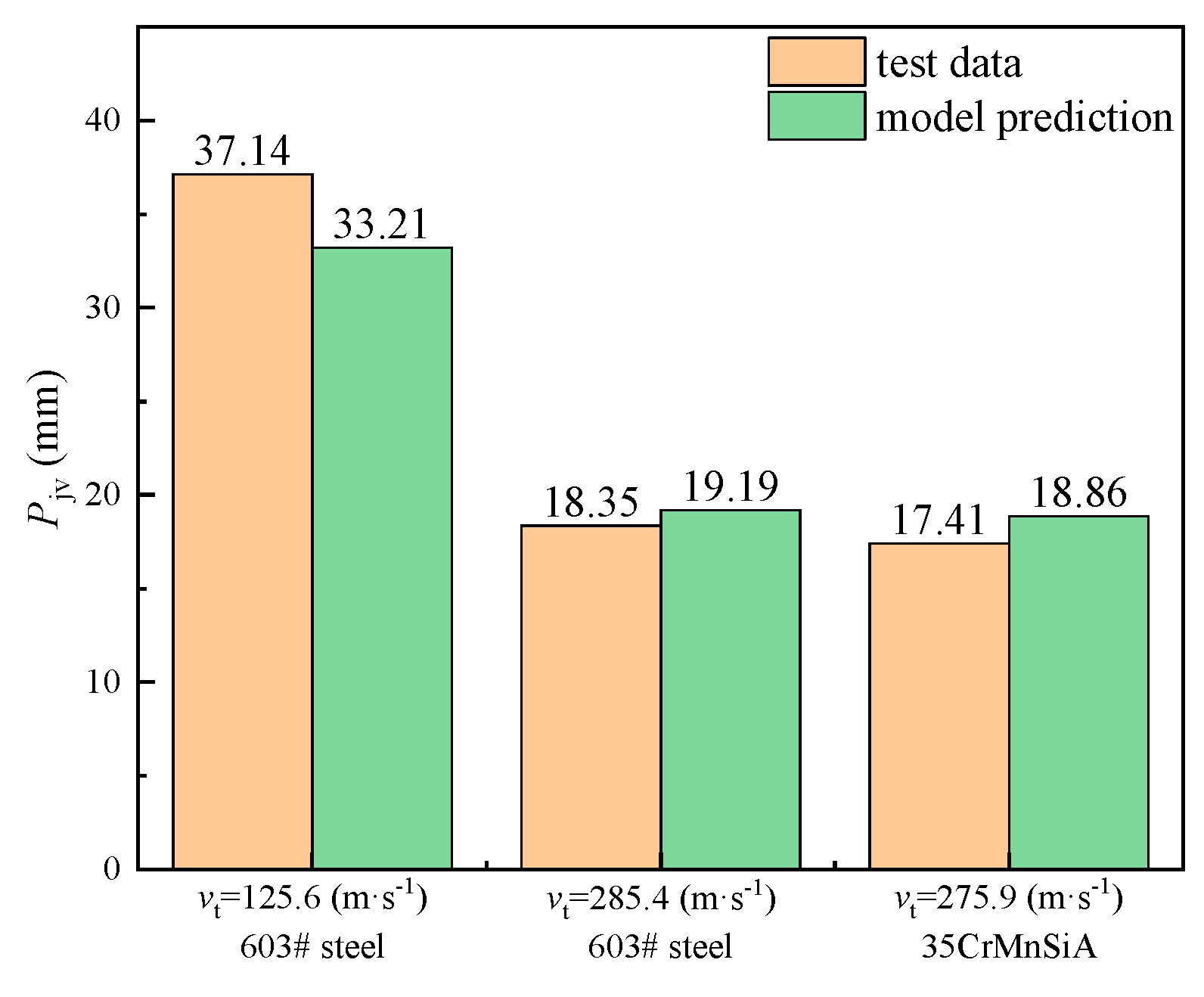
  • A comparison of the numerical simulation, the prediction model and the experimental data under different target velocities, reveals that the relative errors between the established prediction model, numerical simulation and experimental data are all below 15%, showing good consistency. The established engineering model can characterize the influence of target strength.

Author Contributions

Conceptualization, X.Z., C.X. and J.Y. (Jianping Yin); methodology, X.Z.; software, X.Z.; validation, X.Z.; formal analysis, X.Z., C.X., J.Y. (Jianping Yin), X.Z., J.Y. (Jianya Yi) and X.L.; investigation, X.Z., C.X., J.Y. (Jianping Yin), J.Y. (Jianya Yi) and X.L.; data curation, X.Z., C.X. and J.Y. (Jianping Yin); writing—original draft preparation, X.Z.; writing—review and editing, C.X. and J.Y. (Jianping Yin); supervision, C.X., J.Y. (Jianping Yin), J.Y. (Jianya Yi) and X.L.; project administration, X.Z. All authors have read and agreed to the published version of the manuscript.

Funding

This research was funded by the National Natural Science Foundation of China (Number: 12402441); the China Postdoctoral Science Foundation under Grant (Number 2024M760012) and Shanxi Province Basic Research Plan Free Exploration Youth Fund Project (Number: 202203021212136).

Institutional Review Board Statement

Not applicable.

Informed Consent Statement

Not applicable.

Data Availability Statement

The original contributions presented in the study are included in the article, further inquiries can be directed to the corresponding author.

Acknowledgments

The authors would like to thank the editor, associate editor, and the anonymous re-viewers for their helpful comments and suggestions that have improved this paper.

Conflicts of Interest

Author Can Xu was employed by the company Anhui Dongfeng Mechanical and Electrical Technology Co., Ltd. The remaining authors declare that the research was conducted in the absence of any commercial or financial relationships that could be construed as a potential conflict of interest.

References

  1. Hao, Z.; Wang, Z.J.; Xu, Y.J.; Duan, C.; Wang, Y. Study on the detonation wave propagation of shaped charge with three-layer liner and its driving characteristics to liner. Sci. Rep. 2024, 14, 8778. [Google Scholar] [CrossRef]
  2. Fang, Y.Z.; Zhang, X.F.; Xiong, W.; Liu, C.; Tan, M.T. Characteristics of After-effect Parameters of Shaped Charge Jet Penetrating Finite Thickness Steel Target. Chin. J. Energetic Mater. 2024, 32, 899–910. [Google Scholar]
  3. Guo, Y.; Peng, S.; Yang, R. Experimental and numerical simulation study on penetration damage effect of parabolic-shaped charge. Braz. Soc. Mech. Sci. Eng. 2025, 47, 91. [Google Scholar] [CrossRef]
  4. Park, J.; Kwon, S. Study on the penetration performance of a double-angle linear shaped charge: Performance improvement and miniaturization. Aerospace. 2024, 11, 310. [Google Scholar] [CrossRef]
  5. Yin, J.; Wang, Z. Ammunition; Beijing Institute of Technology Press: Beijing, China, 2015; pp. 134–135. [Google Scholar]
  6. Liu, Z.; Yang, R.; Zuo, J.; Xu, P.; Zhao, Y.; Yang, Z. Research on the crack formation mechanism of shaped charge blasting and the new dual-shaped charge blasting technology. Mech. Adv. Mater. Struct. 2024, 32, 374–390. [Google Scholar] [CrossRef]
  7. Jia, X.; Huang, Z.; Xu, M.; Xiao, Q. Theoretical model and numerical study of shaped charge jet penetrating into thick moving target. Acta Armamentarii 2019, 40, 1553–1561. [Google Scholar]
  8. Li, J.; Lu, Y.; Liang, B.; Xu, H.; Chen, X.; Zhang, J. Numerical Study and Theoretical Model of Shaped Charge Jet Penetrating into Thick-Walled Target with Following Velocity. Int. J. Aerosp. Eng. 2024, 2024, 7646255. [Google Scholar] [CrossRef]
  9. Held, M. Shaped Charge Jet Against a Transverse Moving Target. Propellants Explos. Pyrotech. 1999, 24, 325–327. [Google Scholar] [CrossRef]
  10. Frankel, I.; Weihs, D. Hydrodynamic theory of glancing impact. J. Fluid Mech. 1990, 216, 213–229. [Google Scholar] [CrossRef]
  11. Walters, W.P.; Zukas, J.A. Fundamentals of Shaped Charges; John Wiley & Sons: Hoboken, NJ, USA, 1988. [Google Scholar]
  12. Golesworthy, R.C. The effect of transverse velocity on shaped charge performance. In Proceedings of the 7th International Symposium on Ballistics, The Hague, The Netherlands, 19–21 April 1983; pp. 1–15. [Google Scholar]
  13. Jia, X.; Huang, Z.; Xu, M.; Xiao, Q.; Liu, X.; Zhang, X.; Yin, D. Study on Interaction Mechanism between the Shaped Charge Jet and Thick Moving Target. Prop. Explos. Pyrotech. 2019, 44, 1033. [Google Scholar] [CrossRef]
  14. Dorogoy, A.; Rittel, D.; Weihs, D. Effect of target velocity on damage patterns in hypervelocity glancing collisions. Int. J. Impact Eng. 2020, 144, 103664. [Google Scholar] [CrossRef]
  15. Kobylkin, I.F.; Dorokhov, N.S. Interaction of a shaped-charge jet with moving reactive armor plates. Combust. Explos. Shock Waves 2013, 49, 495–500. [Google Scholar] [CrossRef]
  16. Li, G.; Chen, X. A compressible model of radial crater growth by shaped-charge jet impact. Explos. Shock Waves 2022, 42, 97–105. [Google Scholar]
  17. Held, M.; Fischer, R. Penetration theory for inclined and moving shaped charges. Propellants Explos. Pyrotech. 1986, 11, 115–122. [Google Scholar] [CrossRef]
  18. Han, S. Simulation Research on Sunder Armor Oblique Penetrate High Speed Movement; North University of China: Taiyuan, China, 2015. [Google Scholar]
  19. Tan, L.; Zhang, T.; Qiao, L.; Ma, C. Numerical Simulation of Shaped Jet Penetrating Moving Steel Target. Ordnance Ind. Autom. 2021, 40, 6–9. [Google Scholar]
  20. Rassokha, S.S. Numerical Simulation of Jet Formation from a Rotating Shaped Charge. Combust Explos Shock Waves 2024, 60, 811–818. [Google Scholar] [CrossRef]
  21. Wang, Q.; Zhao, H.; Zhao, P.; Shao, X.; Zhang, X. Study on Damage Effectiveness of Shaped Warhead in Air Defense and Anti-missile. Ordnance Ind. Autom. 2018, 37, 60–63, 72. [Google Scholar]
  22. Chen, Z. Analysis of the Characteristics of the Jet from HEAT Projectile with the Error and Simulation Research on Impact into the High-Speed Target in an Angle; North University of China: Taiyuan, China, 2015. [Google Scholar]
  23. Li, R.; Han, H.; Sun, S.; Liu, T. Ballistic resistance capabilities of explosive reactive armors encapsulated by ceramic layers. Explos. Shock. Waves 2014, 34, 47–51. [Google Scholar]
  24. Liang, Y. Study on the Factors Affecting Shaped Energy Jet Oblique Impact into Thin Layer Charge Reactive Armor; North University of China: Taiyuan, China, 2023. [Google Scholar]
  25. Nan, Y.; Jiang, J.; Wang, S.; Fang, Y. Numerical simulation and test for impact response of submunitions drop. J. Vib. Shock. 2013, 32, 182–187. [Google Scholar]
  26. Zuo, H.; Guo, W.; Xu, F.; Zou, J.; Kang, X. Laboratory simulation of deceleration and acceleration process. In Proceedings of the 10th National Conference on Shock Dynamics College of Aeronautics, Taiyuan, China, 1 July 2011; pp. 162–170. Available online: https://d.wanfangdata.com.cn/conference/7559575 (accessed on 1 July 2011).
  27. Zaouk, A.K. Development and Validation of a US Side Impact Moveable Deformable Barrier Fe Model. In Proceedings of the 3rd European LS-DYNA Conference, Paris, France, 18–19 June 2001. [Google Scholar]
  28. Wang, Y.; Yin, J.; Zhang, X.; Yi, J.; Li, X. Study on jet dynamic impact performance under the influence of standoff. Sci. Rep. 2024, 14, 31462. [Google Scholar] [CrossRef]
  29. Feng, K.; Yang, Y.; Chen, Y. Study on Penetrating Stability of Shaped Charge Jet. Ordnance Ind. Autom. 2022, 41, 87–92. [Google Scholar]
  30. Jia, X.; Xu, M.; Huang, Z.; Xiao, Q.; Chen, S.; Ma, B. Theoretical analysis and experimental study of the performance of shaped charge jet penetration into thick-walled moving target by rocket sled testing method. Int. J. Impact Eng. 2021, 155, 103894. [Google Scholar] [CrossRef]
Figure 1. Setup for the numerical simulation model of the jet dynamic penetration. (a) 1. shell, 2. wave shaper, 3. charge, 4. liner, 5. ring, 6. air domain, 7. target plate. (b) The setting for the numerical simulation model.
Applsci 15 06313 g001
Figure 2. Cloud diagram of the velocity of the jet before it hits the target.
Applsci 15 06313 g002
Figure 3. Typical jet dynamic impact process.
Applsci 15 06313 g003
Figure 4. Offset angle α and its variation curve. (a) Schematic diagram of offset angle α; (b) the change curve of offset angle α under different target strengths.
Applsci 15 06313 g004
Figure 5. Typical jet dynamic impact depth curve.
Applsci 15 06313 g005
Figure 6. The relationship between Pj,dyn/l and vt√(ρj/Yp).
Applsci 15 06313 g006
Figure 7. Jet dynamic penetration depth and prediction curve.
Applsci 15 06313 g007
Figure 8. Jet dynamic impact test system and its schematic diagram. (a) 1. baffle, 2. target, 3. probe, 4. track, 5. rockets, 6. charge, 7. rocket pulley; Schematic diagram of the jet dynamic test system; (b) Diagram of the jet dynamic impact test.
Applsci 15 06313 g008
Figure 9. Photograph of a typical jet dynamic impact test.
Applsci 15 06313 g009
Figure 10. Comparison between numerical-simulation results and experimental results.
Applsci 15 06313 g010
Figure 11. Comparison of the jet dynamic impact results.
Applsci 15 06313 g011
Table 1. Parameters of the Johnson–Cook and Grüneisen Models of the copper liner.
ParameterValueParameterValue
ρ/(kg·m−3)8960Tm/°C1356
A/GPa0.09Cp/J·kg−1·K−1383
B/GPa0.292 ε ˙ 0 /s−11
C0.025C/(m·s−1)3940
N0.31s1.489
M1.09γ2.02
Tr/°C293A0.47
Table 2. Parameters of the explosive material.
ρ/(kg·m−3)D/(m·s−1)PCJA/GPaB/GPaR1R2ω
171783200.37524.237.684.21.10.34
Table 3. Material parameters of the shell, wave shaper and target plate.
Materialρ/(kg·m−3)E/GPaσY/GPaβ
aluminum alloy278072.40.3450.5
phenolic resin11300.350.121
603# steel7830202.80.9751
35CrMnSiA80002101.2751
45# steel78302100.3551
Disclaimer/Publisher’s Note: The statements, opinions and data contained in all publications are solely those of the individual author(s) and contributor(s) and not of MDPI and/or the editor(s). MDPI and/or the editor(s) disclaim responsibility for any injury to people or property resulting from any ideas, methods, instructions or products referred to in the content.

