1. Introduction
Magnetic resonance imaging is one of the most widespread diagnostic techniques in the biomedical and clinical fields [
1,
2]. Indeed, compared to PET and X-rays, it exploits the interactions between tissues and a radio-frequency magnetic field. Therefore, due to the absence of ionizing radiation, it is safer for the patients [
3]. In addition, differently from other imaging modalities, it does not require solving an inverse problem to infer tissues properties [
4]. Hence, the use of direct algorithms makes this technology a reliable and convenient means for diagnostics.
Naturally, double-tuned MRI modalities have also been developed, which are able to combine signals coming from multiple chemical nuclei. In this way, anatomical and functional information can be simultaneously acquired, thus enhancing the imaging capabilities [
5,
6,
7,
8]. As an example, many human diseases involve alterations in the regulation of
23Na concentration, although detecting the weak signal emitted by the sodium is, to date, still a challenge. Although these are promising advantages, the scientific community is nevertheless focused on continuously improving MRI performance, particularly in terms of signal-to-noise ratio (SNR), transmission efficiency (TXE), and RF magnetic field spatial homogeneity.
As can be expected, optimizing transmission efficiency while preserving magnetic field homogeneity and enhancing signal-to-noise ratio is extremely challenging. Moreover, these performance parameters must also be considered together with the Specific Absorption Rate minimization, necessarily resulting in a trade-off [
9,
10,
11,
12,
13,
14]. Therefore, researchers are partaking in a great effort to improve MRI performance, and consequently, the image quality. In particular, although the imaging post-processing elaboration plays a very important role in the enhancement of imaging, we will focus on hardware aspects in this work.
In this sense, to improve the transmission efficiency and the detection of smaller signals emitted by the investigated tissue, a solution based on high-permittivity dielectric pads included within the scanner during the procedure has been presented in the literature [
15,
16,
17]. In particular, this technology has been successfully declined for brain scanning, by using a high permittivity material helmet (HPM-helmet) that covered the patient’s head [
18,
19,
20]. According to the Maxwell equations, the magnetic field is enhanced by placing a dielectric material which is able to increase the displacement currents. Although a transmission efficiency improvement up to 65% inside the tissue was observed, this solution is nevertheless extremely cumbersome and heavy, producing discomfort for the patient and difficulties to be integrated within the scanner.
As an alternative to enhancing the SNR, several high sensitivity receiving coils designs, characterized by shapes conformal to the anatomy of the specific investigated tissue, have also been described in the literature [
21,
22,
23]. This approach can be extremely effective but is usually limited to surface coils with a single operating frequency.
Recently, the use of electromagnetic metasurfaces has also been proposed in MRI. Typically, metasurfaces consist of a 2D periodic arrangement of properly designed resonant elements able to show non-natural electromagnetic properties, such as negative permeability or permittivity and also negative refractive index [
24,
25]. Due to their compact dimensions with respect to their 3D counterpart, metasurfaces have recently received a lot of attention in several fields, as well in biomedical applications [
26,
27,
28]. In their first application in MRI, the replacement of the heavy and cumbersome dielectric pads has occurred by implementing dielectric metasurfaces [
29]. The physical idea is that the conductance currents flowing along a periodic array of thin metal strips can create a magnetic field similar to the one produced by the displacement currents inside a high-permittivity material. Besides dielectric metasurfaces, magnetic metasurfaces have also been created for enhancing the RF magnetic field [
30]. In this case, the aim is to increase the equivalent magnetic permeability [
31]. In both the dielectric and magnetic versions, metasurfaces have been proved to be an effective medium to improve the magnetic field distribution and thus, to guarantee significant image quality improvement [
10,
11,
32]. However, to date, a severe limitation of metasurfaces employed in MRI relies on the operating frequency. Indeed, only single frequency metasurfaces have been developed by preventing this promising technology from being extended for multi-nuclei MRI systems.
Therefore, to overcome the actual literature limits and, for the first time to the best of the authors’ knowledge, this paper presents an innovative dual-tuned metasurface able to guarantee dual-nuclei imaging and to enhance the magnetic field distribution for 1.5 T MRI scanners. In particular, the work aims to explore the possibility to improve both the transmission efficiency and the signal-to-noise ratio for 1H and 23Na MRI imaging with a single metasurface, which is able to simultaneously perform at both related Larmor frequencies. This can be translated into the reduction in scanning time, instrumentation complexity, and overall system costs.
From a design perspective, the proposed metasurface comprises a 5 × 5 passive array, in which each unit-cell is properly loaded with a capacitor to control the flowing current by resorting to an opportune analytical model [
32,
33]. To achieve a double-frequency operation, each unit-cell consists of two concentric spiral coils; the internal one resonates at the proton Larmor frequency (64 MHz), whereas the external one is at the sodium Larmor frequency (17 MHz). By interposing the passive metasurface between a standard MRI RF loop and the biological tissue, the overall transmission efficiency
and signal-to-noise ratio improvements are evaluated at both the operating frequencies. In particular, theoretical and numerical results are supported by workbench measurements acquired on fabricated PCB prototypes.
The remainder of the paper is organized as follows.
Section 2 describes the imaging system design and the analytical model behind the proposed solution. Further, the numerical and experimental test-cases are also reported in
Section 2, while
Section 3 is devoted to presenting the numerical and experimental results. Finally, conclusions and future developments are discussed.
2. Materials and Methods
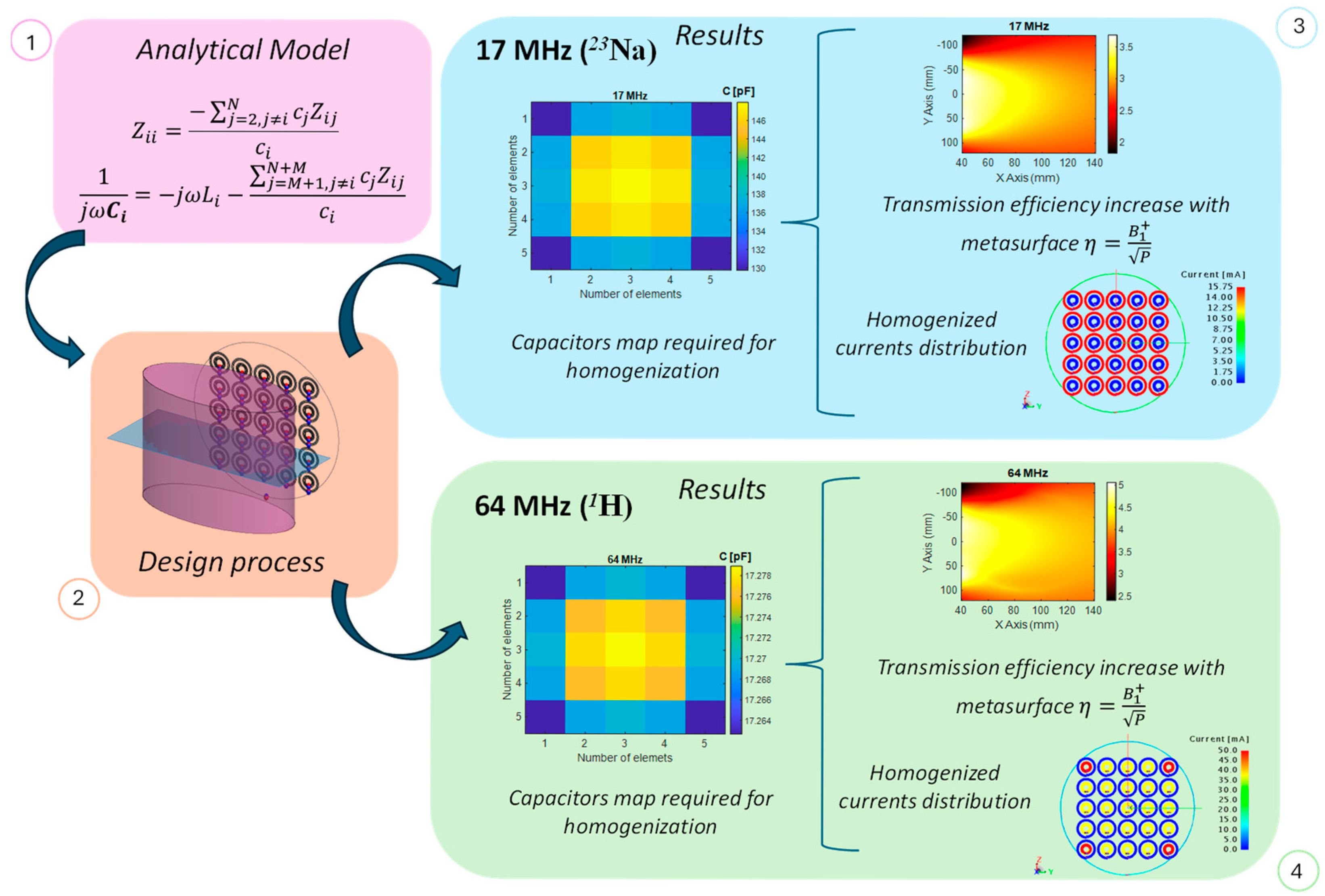
A flow chart of the proposed methodology is summarized in
Figure 1. It starts with a theoretical model applied on the numerical design, finally accomplishing the prototyping process. In the next sections, a detailed explanation of the various steps is reported.
2.1. Theoretical Model
As previously introduced, magnetic metasurfaces are specially engineered structures capable of exhibiting unconventional properties, such as enhanced or even negative magnetic permeability. Typically, they consist of arrays of resonant unit cells, whose dimensions are determined by the operating frequency and critically influence the resulting magnetic field distribution. When appropriately designed, the entire metastructure exhibits resonant behavior, allowing the effective magnetic permeability to be tailored over specific frequency bands and enabling the enhancement of the magnetic field strength, in accordance with Maxwell’s second equation.
where
and
are, respectively, the magnetic induction and the electric fields;
and
are, instead, the vacuum magnetic permeability and dielectric permittivity;
is the relative magnetic permeability;
, where
is the operative frequency. Finally,
is defined as the current density. Therefore, according to (1), it is possible to enhance the magnetic field strength by increasing both the conductance and the displacement currents, acting on the engineered relative magnetic permeability realized by the metasurface.
One of the most important MRI RF coil parameters, fundamental for imaging quality, is the homogeneity of the generated magnetic field. It is important to note that electromagnetic metasurfaces are typically designed under the assumption of infinite extent, which inherently ensures a homogeneous response. In such cases, each unit cell shares identical boundary conditions—being surrounded by an infinite array of neighbors—and consequently carries the same current distribution. However, at relatively low operating frequencies, such as those used in MRI, the physical size of each unit cell becomes large enough that only a limited number can be used to construct the metasurface. Under these conditions, where the metasurface is finite, edge or truncation effects can become significant, potentially degrading the performance in terms of magnetic field homogeneity. It is easy to understand that only the central unit-cells are surrounded by a large number of elements, while, on the external borders, an asymmetry can be spotted. For this reason, to restore the ideal metasurface behavior, an analytic algorithm is employed to control each unit-cell current [
32], and thus, the overall magnetic field distribution. Specifically, by accounting for both the self-impedance of each unit cell and the mutual coupling between them, it becomes possible to compensate for the truncation effects associated with the finite size of the metasurface. If the active RF coil used to excite the metasurface is denoted as element 1, and the metasurface unit cells are indexed from 2 to
N, the overall system can be described using an impedance matrix as follows:
where the current flowing in the
i-th cell can be written as follows:
in which
is the
i-th complex current coefficient and
is an arbitrary reference value.
By enforcing resonance conditions for each element of the array at the target operating frequency, the required reactance for each unit cell can be determined to achieve the desired response of the metasurface:
Although arbitrary current distributions can be synthesized, we set all coefficients equal to 1 in order to mitigate truncation effects and ensure a homogeneous magnetic field distribution. Specifically, the algorithm calculates the values of the capacitors that must be connected in series with each unit cell to achieve the desired current control.
As described in the introduction, the proposed metasurface is conceived to operate at two different frequencies, at the same time. Therefore, the metasurface unit-cell design is slightly more complicated, relying on two concentric spiral coils resonating at the two desired frequencies. Specific attention must be paid to the mutual coupling between these two concentric spirals, that must be minimized to avoid crosstalk between them.
Finally, the transmission efficiency
and the signal-to-noise ratio (SNR) are adopted as metrics to assess the accomplished performance, both in presence and in absence of the metasurface. In particular, as reported in the literature, the transmission efficiency can be evaluated as follows:
where
is the magnetic field component which rotates in the same direction as the nuclear precession and
is the power provided by the generator.
Instead, the SNR of the image can be expressed as follows [
34]:
where
θ is the excitation flip angle;
is the receive field and
is the coil accepted power.
In the following section, we present the numerical and experimental set-up, conceived to prove the effectiveness of our approach.
2.2. Numerical Design Procedure
In order to validate and demonstrate the described approach, we realized a numerical set-up, by employing an electromagnetic full wave solver based on the Method of Moments (Feko Suite, Altair, USA). The overall set-up comprises an active RF loop, the dual-tuned magnetic metasurface and a biological phantom (
Figure 2).
In detail, the proposed metasurface consists of a passive 5 × 5 array, covering a 15 cm × 15 cm area, in which each unit-cell is composed of two concentric resonant spiral coils. Specifically, the 5-turn internal spiral is made resonant at 64 MHz, whereas the 4-turn external one is at 17 MHz, taking into particular consideration their mutual coupling. The inner spiral presents an external diameter of 17 mm, with a spiral pitch of 0.9 mm; the outer one, instead, has a 29.2 mm external diameter with the same pitch. The passive metasurface is inductively excited by a circular RF loop, presenting a 20 cm diameter and placed 5 mm far from the array. Both the metasurface and the RF loop are fabricated with a 28 AWG single strand lossy copper wire. The corresponding CAD model, including a biological phantom and the transversal plane where the
field is evaluated in the following sections, is depicted in
Figure 2. Conversely, all the system geometrical properties are summarized in
Table 1.
As is well known, the mutual coupling term in the inductive regime between two coils is directly proportional to their self-inductances, while being inversely proportional to the relative distance. By considering this phenomenon, we paid special attention to the metasurface unit-cells design and positioning. In particular, a design optimization process was followed to minimize the mutual coupling coefficient between the two spirals constituting the single unit-cell. The different operating frequencies (17 and 64 MHz) are in part helpful in limiting the coupling, but a proper spatial distance between these two elements must also be accomplished. By carefully optimizing the geometry and the periodicity of the unit-cells, an acceptable trade-off can be found.
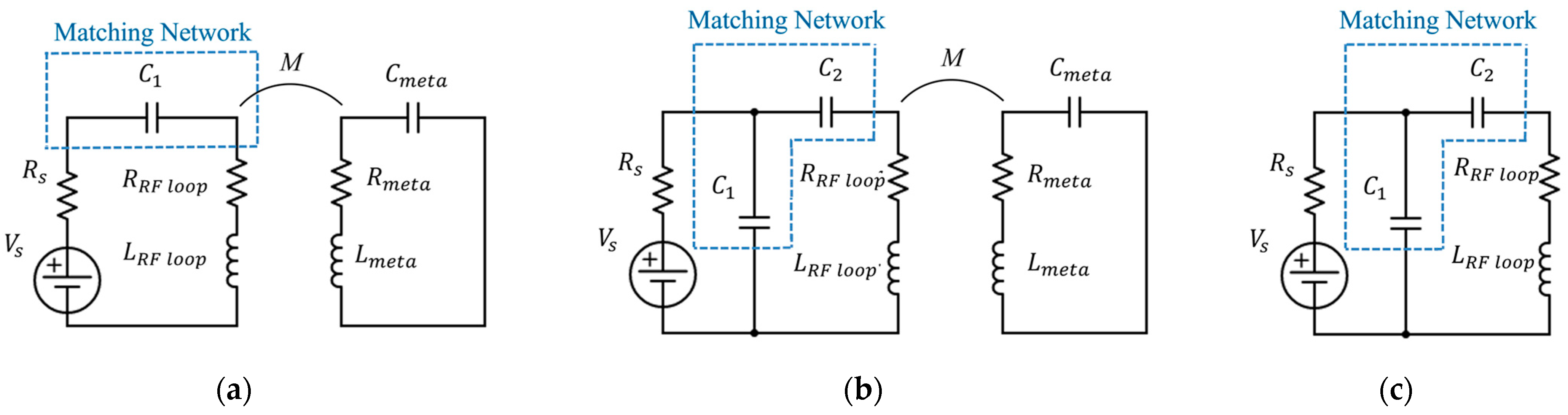
After taking care of the geometry, we then proceeded by applying the analytical algorithm described in the previous section to compensate for the truncation effects. Thus, we loaded each coil with the appropriate capacitor, homogenizing the current flowing in each unit-cell and, consequently, the produced magnetic field. In addition, in order to maximize the power transmitted to the metasurface, we designed two different matching networks for the active RF loop, at 17 MHz and 64 MHz, whose topologies are described in
Figure 3. The corresponding lumped elements values are reported in
Table 2.
Finally, we also introduced the presence of a biological phantom to realize a realistic scenario, simulated with a cylinder with an ellipsoidal base presenting a major axis equal to 100 mm and a minor axis equal to 50 mm (
Figure 2). The total phantom height is 200 mm, while the corresponding dielectric properties are set to simulate muscle tissues, and they are estimated from [
35].
To demonstrate the validity of the method, we performed two full-wave simulations for each frequency (17 and 64 MHz) with and without the presence of the metasurface between the RF loop and the investigated tissue, carefully evaluating the obtained magnetic field distributions.
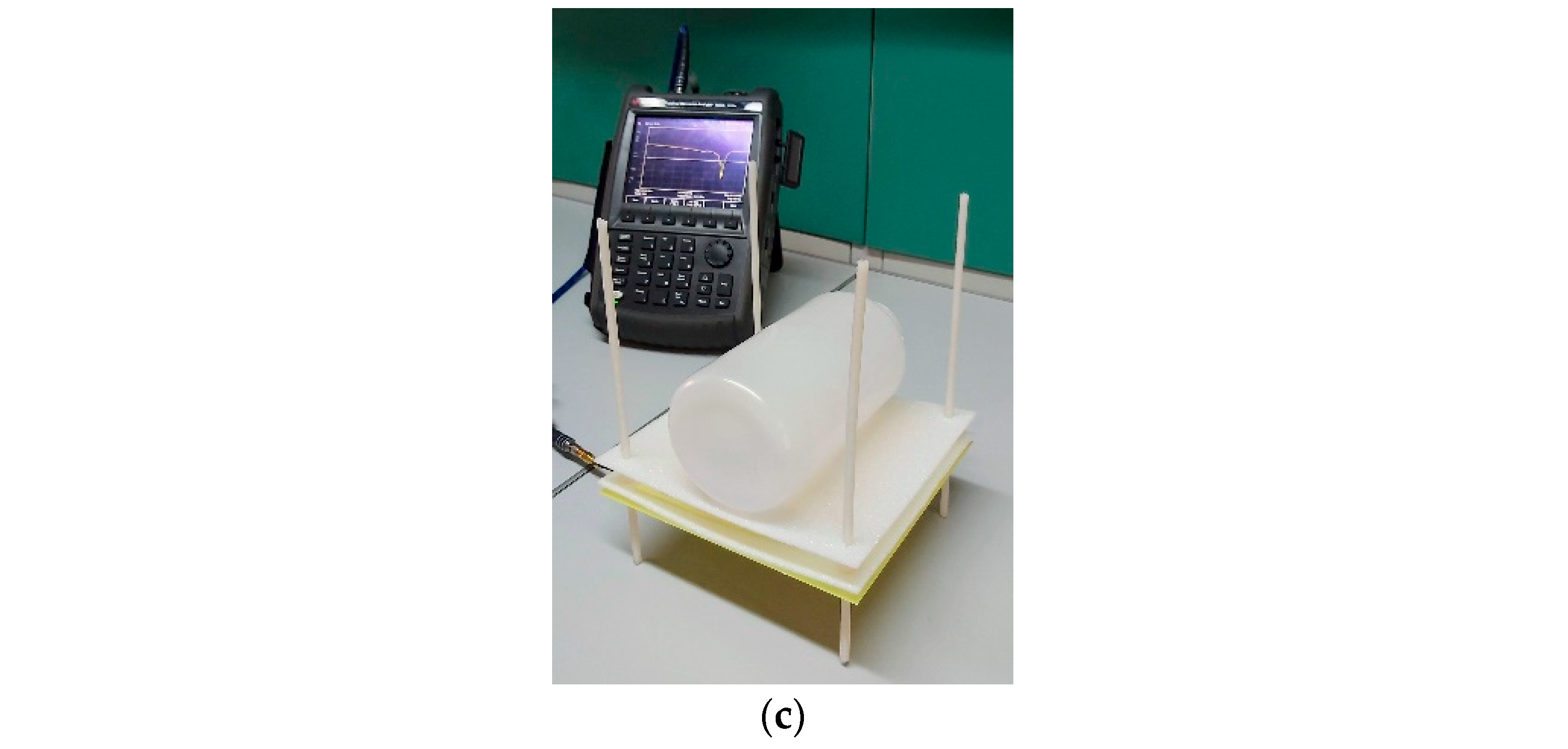
2.3. Fabricated Prototype
To experimentally support the numerical approach, we also fabricated a prototype (
Figure 4). In particular, both the metasurface and the RF loop were realized by using PCB technology. The metasurface was etched over the top layer of a 0.1 mm thick FR4 substrate (
= 4.3 and
tanδ = 0.025), whereas, on the other side the evaluated capacitors were soldered according to the numerical design process. Since we used AWG single strand copper wires in the numerical design to computationally speed up the simulations, we designed the PCB printed coils according to the following relation [
36] to guarantee the inductance equivalence.
where
is the printed strip width and
is the wire radius.
Because the metasurface can be used to enhance the magnetic field both in transmission and reception, special attention must be paid to the capacitor’s choice. Indeed, especially in transmission, relatively high power levels must be handled, therefore, appropriate ceramic capacitors have been consequently selected [
37]. On the other hand, the RF active loop was etched on the top layer of a 0.8 mm thick FR4 substrate. Also in this case, we soldered on the bottom layer the components of the matching networks at the two frequencies (
Figure 4). Finally, we equipped the RF loop with a 50-Ω-micro-SMA connector to enable measurements with a vector network analyzer (Fieldfox series VNA N9918A, Keysight, Santa Rosa, CA, USA). Lastly, we realized a muscle phantom (
Figure 5) by using a cylindrical plastic container (200 mm height with a circular base presenting a 100 mm diameter), filled with a mixture of water, glycine (
) at 12%
w/
v, and NaCl at 0.53%
w/
v, following the methodologies described in [
35,
38]. It is important to note that the relative positioning among RF coil, metasurface, and phantom must respect the distance values optimized during the design process to guarantee the maximum performance of the overall system.
3. Numerical and Experimental Results
As a first step, we numerically evaluated the mutual coupling between the two concentric spirals constituting the single unit-cell. Indeed, in order to have the metasurface working simultaneously at both the desired frequencies (17 and 64 MHz), it is particularly important that the two concentric spirals of a single unit-cell are sufficiently decoupled at the respective operating frequencies. The results, shown in
Figure 6, demonstrated that the two concentric spirals present a low coupling level, although larger at 64 MHz. While this value is acceptable in terms of performance, room for improvement is still available in this parameter.
We therefore proceeded with the unit-cell’s currents homogenization procedure. By following the calculations performed in the previous section, we loaded each element of the metasurface with the appropriate capacitor in order to avoid truncation effects. In
Figure 7a,b, the maps of the capacitive loads at 17 MHz and 64 MHz are reported. As apparent from
Figure 7b, the capacitance values at 64 MHz do not depend in essence on the unit-cell position within the metasurface. This is due to the larger periodicity for the unit-cells internal spirals, which results in a lower reciprocal mutual coupling (and, thus, less correction required for homogenization).
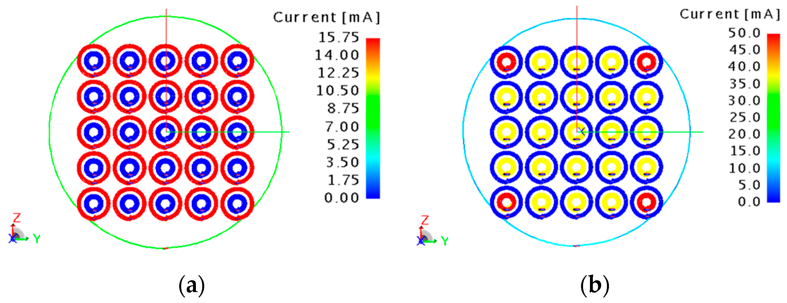
Once the loads are applied, the currents flowing in the unit-cells are homogenized for both the operative frequencies, as is evident in the numerical results reported in
Figure 8a,b. Due to the not completely negligible mutual coupling between the single unit-cell external and internal spirals at 64 MHz, a minor deviation (not affecting in practical aspects) from perfect homogenization can be spotted at the four metasurface corners. Notably, when the metasurface is working at a specific frequency (e.g., 17 MHz), the current does not flow in the coils tuned at the other frequency (e.g., 64 MHz), as expected. Another important metric, as explained before, relies on the transmission efficiency evaluation. In
Figure 9, we reported the numerical transmission efficiency increase achievable thanks to the metasurface adoption, respectively, without (
Figure 9a,b) and with (
Figure 9c,d) the presence of a biological phantom, at 17 MHz and 64 MHz. As is evident, in the absence of the biological phantom, the transmission efficiency increases by a factor 4.5 (at 17 MHz) and 5.5 (at 64 MHz). Instead, in the presence of the phantom, we obtain an increase in a factor 3.5 and 5 at 17 MHz and 64 MHz, respectively. Since the same RF coil and metasurface are used to receive the signal, the
also increases by the same factor of the
by the principle of reciprocity [
36]. Therefore, in the reasonable hypothesis that the biological load losses are dominant, the SNR percentage enhancement obtained with the metasurface is also represented by the map reported in
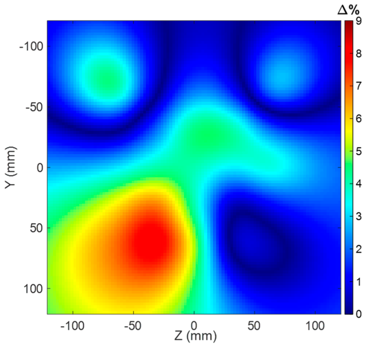
Figure 9c,d. In addition, we also investigated the effect that capacitor’s tolerances, which are unavoidable in practical scenarios, can have on the field map produced by the metasurface. Therefore, we randomly assigned a ±1% tolerance (a typical commercial value) to the capacitances determined in
Figure 7. After that, we evaluated the H-field map on a plane parallel to the metasurface and 40 mm distant from it. By comparing the map obtained with the ideal capacitor’s values of
Figure 7 and the one with tolerances, we found that the maximum percentage deviation happens for the 64 MHz Larmor frequency. As can be observed from
Figure 10, the maximum field deviation due to the tolerances remains under 9%, thus proving the robustness of the proposed solution.
Further, we proceed with the experimental measurement campaign employing the fabricated prototype.
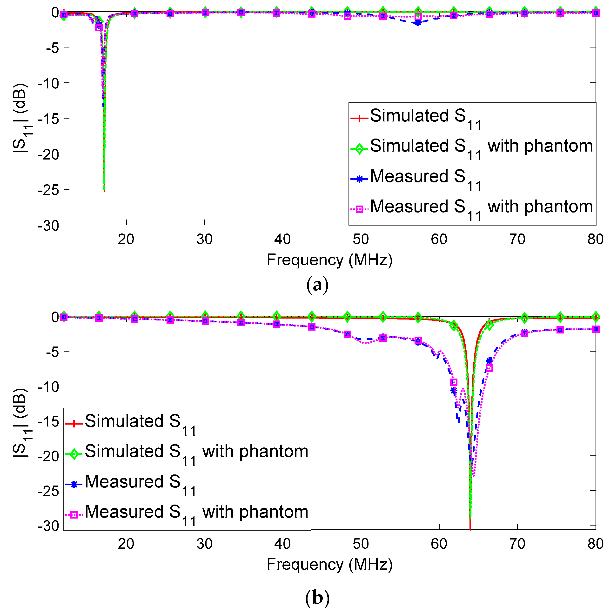
Figure 11 shows the simulated and measured
parameters for the RF loop with the metasurface, for both 17 MHz and 64 MHz and with and without the biological phantom load. As is evident, in all cases, the reflection coefficients are less than −10 dB, proving the effectiveness of the matching networks computed in the design process. In particular, the presence of the phantom does not significantly change the reactive part of the input impedance of the system, and, consequently, the matching is preserved. Comparing the numerical and experimental results, it is possible to conclude that the effectiveness of the overall fabrication process is satisfactorily demonstrated.
Finally, the adopted fabrication technique based on PCB manufacturing ensures the required mechanical stability and electrical and thermal robustness in operative MRI scenarios, thus straightforwardly enabling a future implementation in real scanners [
37].
4. Conclusions
In this paper, a novel passive dual-tuned magnetic metasurface for 1.5T MRI 1H and 23Na imaging has been proposed. In particular, the dual-tuned metasurface is able to enhance the magnetic field strength both in transmission and receiving phases and for both the required Larmor frequencies simultaneously. The final metasurface design consists of a 5 × 5 passive capacitively loaded array, in which each unit-cell is composed, in turn, of two concentric spirals. The two concentric spirals are responsible for the dual-frequency metasurface response, since they are made resonant at the two Larmor frequencies, i.e., 17 and 64 MHz. Due to the metasurface finiteness and consequent truncation effects, an appropriate compensation loading procedure was carried out through an analytical model. This correction led to homogenization of the unit-cells current distribution, thus avoiding the metasurface response degradation while also enhancing the magnetic field strength.
To validate the proposed solution, we conceived a numerical test-case, comprising a RF loop and a metasurface placed 5 mm above it. Next, we performed full-wave simulations with and without the presence of the metasurface, when the radiative system is loaded with a representative biological load. The performance of the metasurface with respect to the single RF loop was evaluated in terms of transmission efficiency . A significant improvement of factor 3.5 at 17 MHz and of 5 at 64 MHz was observed in the presence of the biological phantom. Finally, we also fabricated PCB prototypes, achieving excellent agreement with the simulations in terms of parameters, proving the overall design procedure effectiveness.
To conclude, this solution can be potentially helpful in the MRI multi-nuclei diagnostic technique, allowing for better image quality by using the same hardware configuration, thus reducing the scanning time, the invasiveness on the patient and the final overall costs. Clearly, several aspects must be addressed before the solution can be adopted in actual MRI clinical imaging, as evaluating its robustness for different human districts and size scalability. Therefore, future works will be directed to apply and refine the solution in a real clinical scenario, addressing the aforementioned issues.


 ,
, 


