1. Introduction and Motivations
The Square Kilometre Array Observatory (SKAO) is a next-generation international radio astronomy project designed to become the most sensitive and versatile radio telescope ever constructed. Covering a broad operational frequency range from 50 MHz to 15.3 GHz [
1], it aims to advance the understanding of fundamental astrophysical phenomena, including galaxy formation, cosmic reionization, and gravitational wave events [
2]. The observatory consists of three interconnected sites, namely a central headquarters based in the United Kingdom and two geographically distributed radio telescope arrays: SKA-Low in Western Australia, operating between 50 and 350 MHz; and SKA-Mid in South Africa, covering the 350 MHz to 15.3 GHz band. Besides other aspects, these sites were strategically chosen for their low levels of radio-frequency interference, thereby ensuring optimal observing conditions [
3].
To overcome the intrinsic limitations of single-element antennas, the SKAO employs radio interferometry, a technique that coherently combines signals from spatially distributed receivers to emulate a telescope with an aperture equivalent to the maximum baseline. This technique significantly enhances angular resolution, enabling high-fidelity imaging and efficient large-scale sky surveys [
4].
SKA-Low consists of 131.072 dual-polarized log-periodic antennas, organized into 512 stations with baselines extending up to 74 km. In contrast, SKA-Mid comprises 197 offset-Gregorian reflector antennas, each equipped with a 13.5 m dish and single-pixel feeds [
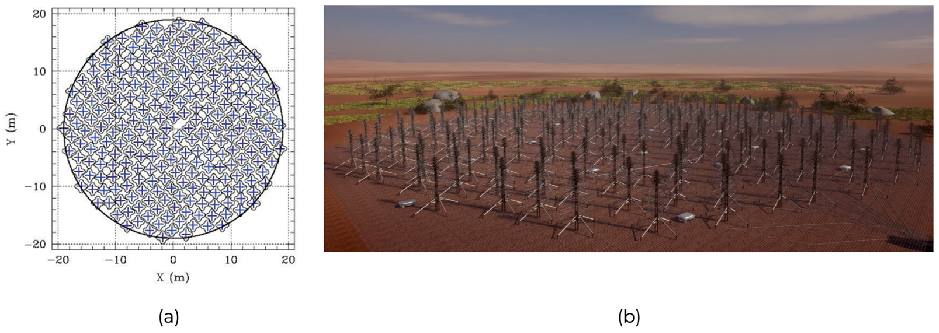
5] and reaching a maximum baseline of 150 km. For both radio telescopes, the array layout configuration, characterized by a dense central core and logarithmic spiral arms (see
Figure 1), is optimized to balance sensitivity and spatial resolution, enabling the SKAO to explore the universe with an unprecedented level of detail [
1,
3]. Given the very large number of antennas and stations in both SKA-Low and SKA-Mid, it is essential to employ design techniques that are extremely effective from a computational point of view, that is, in fact, the aim of the present research work.
Coming to details, this study focuses on SKA-Low, with particular attention to the current antenna implementation, i.e., Square Kilometer Array Log-periodic Antenna (SKALA) 4.1 [
6]. A primary challenge in its design lies in the optimization of key performance metrics such as sensitivity, angular resolution, and survey speed, while simultaneously mitigating interference and minimizing noise contributions.
The development of the Aperture Array Verification Systems (AAVSs) plays a critical role in evaluating end-to-end performance across a range of deployment scenarios. Over time, AAVS prototypes have undergone multiple design refinements. Early versions (AAVS1 and AAVS2) employed pseudo-random layouts (see
Figure 2a), which effectively suppressed mutual coupling and reduced far-field sidelobe levels. Nonetheless, residual inter-element coupling introduced spectral anomalies, particularly at 55 MHz and 77 MHz [
7], primarily due to current imbalances in the bow-tie dipoles.
To address these issues, exclusion zones around the antennas, enforcing a minimum inter-element spacing of 2.5 m along directions within 20° of the principal axes were recently proposed [
8]. While this approach partially mitigated coupling-related artifacts, the resulting irregular and dense arrangement poses practical challenges for physical access and maintenance.
To improve spatial uniformity and accessibility, AAVS3 adopted a more structured (sunflower-inspired) layout based on a Vogel pattern, as shown in
Figure 2b. This configuration distributes antenna elements with a radial density proportional to the square of the distance from the array center [
8], resulting in high spatial uniformity and a dense filling factor. However, this layout gives rise to elevated sidelobe levels [
9], which degrade the array’s sensitivity to faint astronomical signals by reducing noise immunity and increasing susceptibility to interference. Another issue with this layout is a strong resonance around 125 MHz, which perturbs the array station beam and, consequently, affects the spectral smoothness [
10].
These trade-offs highlight the need for an advanced and systematic approach to optimizing the elements’ layout and weights to reconcile spatial uniformity with electromagnetic performance. As a result, a revised station configuration has been adopted [
11]; however, a comprehensive beamforming analysis is still pending.
The challenges outlined above necessitate a combined optimization of both the array elements’ layout and weight coefficients. The goal of this work is to determine a set of weights that maximize the receiving pattern in a desired target direction while simultaneously minimizing sidelobe levels across the remainder of the angular domain. Due to reciprocity arguments, this goal is equivalent to a classical synthesis problem in array antenna design [
12].
In fixed-geometry arrays, where the elements’ positions are defined in advance and only the elements’ weights are subject to optimization, globally optimal solutions have been developed for both pencil [
12,
13,
14,
15,
16,
17] and difference [
18] beams, even under arbitrary sidelobe constraints. These methodologies are applicable to a wide variety of array configurations, including linear, planar, and conformal geometries, provided that the element locations remain fixed.
In particular, the framework proposed in [
12,
14] reformulates the synthesis task, i.e., maximizing the field (or its derivative) in a target direction while constraining the field elsewhere, as a Convex Programming (CP) [
12,
14] or Linear Programming (LP) [
13] problem. This formulation guarantees global optimality and is naturally extendable to directivity maximization under prescribed sidelobe constraints. Moreover, recent developments have enabled the use of phaseless data in synthesis problems [
19], leveraging phase retrieval techniques [
20] to achieve optimal excitation design for arbitrary radiation footprints.
This work applies the methodology presented in prior studies on optimal field focusing under arbitrary Upper Bounds (UB) [
12,
14] to enhance the electromagnetic performance of SKA-Low stations. The analysis addresses constrained optimization scenarios in which the degrees of freedom are amplitudes and phases of the element weight coefficients, under the assumption of a fixed-geometry array. As previously demonstrated in [
12,
14], this approach enables a well-balanced trade-off between key performance metrics, such as directivity and sidelobe suppression, while ensuring globally optimal solutions tailored to the operational requirements of SKA-Low.
It is worth noting that direct experimental validation is infeasible, as full-scale testing would require the deployment of all 256 SKALA 4.1 antennas over a 35 m-diameter station in a low-interference environment, as well as a real-time digital beamforming system. Furthermore, simplifying the setup by reducing the number of antennas would significantly misrepresent the mutual coupling and the other electromagnetic interactions, compromising the relevance of the results. As an accepted and practical alternative, this study relies on full-wave electromagnetic simulations using realistic embedded element patterns, providing high-fidelity emulation of the SKA-Low’s physical behavior. This forms a sound conceptual validation framework for the proposed method. Additionally, this study lays the groundwork for future experimental activities, which will be explored in an upcoming international project that integrates numerical optimization with practical calibration strategies for SKA-Low.
The remainder of the paper is organized as follows.
Section 2 describes the proposed synthesis framework, while
Section 3 details the methodology.
Section 4 presents and discusses the achieved numerical results, and
Section 5 concludes the paper.
2. The Proposed Approach
The component of interest in the receiving pattern of a generic array antenna composed of
-elements can be expressed as follows:
where
and
denote the elevation and azimuth angle with respect to the array’s boresight, while
represents the complex weight applied to the
-th element. The term
is the embedded element pattern of the
-th antenna element, computed with respect to a common origin shared by the entire array. As a result, the phase contribution typically associated with the array factor is inherently included in the EEP. This pattern represents the electric field radiated when the
-th element is excited with a unit weight, while all other elements are terminated with matched loads (typically 50 Ω). Note that this formulation inherently accounts for mutual coupling effects [
21].
The objective is to maximize the difference between the field amplitude in the target direction and that in the sidelobes’ region by optimally controlling the array element weights. This leads to a substantial reduction in interference from undesired directions, thereby enhancing the overall electromagnetic performance of SKA-Low stations.
The proposed approach is grounded on a mask-constrained power synthesis framework, which is particularly well-suited for forming a narrow pencil-beam while limiting radiation in non-target directions. This characteristic is critical for radio astronomy applications such as SKA-Low, where minimizing both terrestrial and celestial interference is a fundamental requirement. The synthesis is formulated as a convex optimization problem, drawing from established techniques for optimal field focusing under arbitrary upper bounds [
12,
14].
The adopted framework is based on a number of key modeling assumptions, which reflect both the design of the SKA-Low station, as well as the constraints imposed by the available data as detailed in the following. First, the array geometry follows a Vogel spiral distribution [
Figure 3b], which provides quasi-random spatial sampling while preserving rotational symmetry and is well known as an effective strategy for reducing grating lobes in large-aperture systems. Second, the antenna element model is derived from the copolar component of the SKALA 4.1 radiation pattern. This choice is consistent with the available full-wave electromagnetic data. Third, the array is modeled as a sparse one, in line with the physical design of the station. In fact, sparsity can mitigate mutual coupling while inducing some limitations on the degrees of freedom available for excitation control.
These assumptions influence both the structure of the synthesis procedure and the interpretation of the results. In particular, while the framework prioritizes sidelobe level (SLL) suppression across the full angular domain (which is a key requirement for high-dynamic-range sky imaging), the corresponding trade-off is a moderate reduction in directivity. This outcome is consistent with expectations as, in sparse arrays, redistributing energy away from the main beam to suppress sidelobes typically leads to slight broadening of the beam and reduced gain. As shown in the results, the achieved sidelobe suppression and the associated directivity loss reflect a balanced and physically meaningful optimization outcome, fully aligned with the assumptions embedded in the problem formulation.
To describe the optimization process in detail, let denote the target direction in which the receiving pattern intensity has to be maximized. The optimization problem is then posed as follows:
Find
such to:
subject to:
where
is an arbitrary upper-bound function enforced in the sidelobes’ region, while
and
denote the real and imaginary parts, respectively.
Note that the objective function (2) is designed to maximize reception in the target direction, while the constraint (3) enforces a purely real field component at that point. Instead, the constraint (4) limits the sidelobe levels to remain within the defined mask . Given that (4) is a positive semi-definite quadratic form, constraints derived from its angular discretization are convex. Additionally, both the real and imaginary part of are linear with respect to the unknown weights , ensuring that the feasible region defined by the constraints remains convex. Consequently, the intersection of these constraints defines a convex set in the solution space.
Therefore, the problem qualifies as a CP optimization and, hence, the identification of the global optimum is guaranteed even when employing fast local-optimization techniques [
12]. This feature makes the proposed approach particularly well-suited for maximizing antenna performance, especially in the context of SKA-Low, where the very large number of elements in each station makes computational efficiency a critical factor. Furthermore, the proposed technique can be applied (and guarantees the global optimality of the corresponding solution) regardless of the operating frequency and the array layout geometry. It also enables simultaneous optimization of receiving patterns at multiple frequencies, further expanding the applicability and relevance of the design procedure and associated tools.
3. Materials and Methods
The proposed design and synthesis framework consists of two main stages: (i) full-wave electromagnetic simulation of the SKALA-4.1 antenna (
Figure 4) [
22] in its array configuration using FEKO (licensed by Altair Engineering [
23]); (ii) post-processing and optimization phase carried out in MATLAB 2024b, aimed at improving the overall station-level radiation characteristics.
3.1. Full-Wave Simulation of the Radiating Element (FEKO)
The SKALA-4.1 antenna, a dual-polarized log-periodic dipole array manufactured by Sirio Antenne, was modeled in FEKO [
23,
24]. The antenna consists of 19 triangular dipoles and a bow-tie dipole, mounted on a dual-conductor boom above a metallic ground mesh. To simplify simulations, the ground mesh was modeled as an infinite perfect electric conductor, thereby implementing the image theorem and consequently reducing meshing complexity.
Given the antenna’s dual-polarization characteristics, simulations were performed for both polarizations. The outcomes demonstrate minimal cross-coupling between the polarizations. The design and simulation processes are based on established techniques detailed in references [
22,
25], while the construction of the prototype aligns with the specifications provided in reference [
6].
To optimize computational efficiency, non-essential structural elements, such as screws and plastic fittings, were omitted from the model. These adjustments maintained the antenna’s electrical performance while significantly reducing the mesh complexity from an initial 29,000 unknowns to approximately 10,000, as noted in [
22].
The feed structure was represented by a square-shaped port with an area equivalent to the original circular connector. A differential voltage source was applied at the intersection of the booms to emulate balanced excitation, ensuring accurate impedance behavior with simplified geometry. Detailed modeling guidelines for reproducibility are available in [
22,
25].
After validating the single-element model, a full station array was constructed (
Figure 3) and its simulated power pattern (
Figure 5), consisting of 256 SKALA-4.1 antennas arranged in a configuration based on Vogel’s spiral distribution. The simulated array spans a circular aperture of approximately 35 m in diameter, with inter-element spacing constrained by SKA-Low mechanical design rules. The Vogel spiral configuration ensures high packing density with quasi-random spacing, and all antennas were modelled at a reference frequency of 350 MHz. Mutual coupling effects are inherently accounted for through the use of EEPs computed by the full-wave electromagnetic simulator. The array configuration and mesh parameters were selected to reproduce, as closely as possible, the physical SKA-Low station layout, ensuring both realism and reproducibility.
The radiation patterns were evaluated over a spherical grid with 0.5° angular resolution, ensuring sufficient spatial sampling for pattern reconstruction [
26].
3.2. Preprocessing and Optimization (MATLAB)
Post-simulation data from FEKO were imported into MATLAB for further processing, which included geometric phase correction, polarization projection, and optimization of excitation weights via convex programming.
Geometric Phase Correction
To account for the relative positions of the antennas within the array, a geometric phase correction was applied. Each antenna’s EEP was initially simulated with the origin of the local reference system centered at each element position. Then, to express the field relative to the global center of the array, the following phase transformation was applied to both components of the radiated field:
Here, denotes the original phase when the antenna is centered in its local reference system, and is the corrected phase relative to the array center. The terms , , and represent the spatial offsets of each antenna from the array center, and is the wavelength.
Copolar Field Component Extraction
After applying the phase correction, the copolarized field component was derived using Ludwig’s formula [
27]. The copolar component for each EEP was computed as follows:
where
and
represent the unitary vectors associated respectively with elevation and azimuthal angle.
This projection yields the field component aligned with the desired polarization direction, which is essential for a consistent evaluation of the power pattern.
From a practical point of view, the EEPs were structured into two complex-valued 3D tensors representing the φ and θ components, each of size 720 × 181 × 256 (azimuth × elevation × element index). The two tensors were then combined through vector summation to yield the vectorial EEPs.
Weight Optimization via Convex Programming
As a preliminary reference, a station pattern was computed using uniform (unitary) weights for all elements.
To suppress sidelobes and enhance directivity, a convex optimization problem to maximize the main lobe gain in a target direction while constraining sidelobe levels to remain below a threshold, set to −25 dB.
The optimization was executed using MATLAB 2024b’s fmincon function with the Active-Set algorithm, which showed superior performance compared to the Interior-Point method in this application, offering faster convergence and greater stability under the given constraints.
4. Results and Discussion
This section presents a comprehensive analysis of the numerical results obtained to evaluate the performance of the proposed synthesis strategy. The objective was to assess the enhancement in radiation characteristics achieved by transitioning from a conventional uniform excitation scheme to an optimized excitation profile derived through convex optimization.
The simulation campaign was conducted at a central frequency of 350 MHz using the EEPs generated from full-wave electromagnetic modeling, as described in
Section 3. Two excitation configurations were analyzed: (i) uniform excitation, in which all elements are driven with equal amplitude and phase; and (ii) optimized excitation, where complex weights were determined by solving the constrained optimization problem defined in
Section 2, imposing
dB for
.
To ensure that the optimization addressed the entire radiation space, the synthesis procedure was executed over a dense spherical grid consisting of 720 azimuthal samples and 181 elevation points.
Although the main beam was steered towards the zenith (), the optimization did not focus on a single angular slice. Instead, the sidelobe suppression constraints were applied globally across all azimuthal cuts and elevation angles, resulting in a pattern that is uniformly optimized over the full 3D angular domain. The formulation aimed to maximize the real part of the field in the zenith direction while simultaneously imposing two critical constraints: the imaginary part at the zenith was constrained to zero to ensure phase coherence, and the field amplitude elsewhere was required to remain below a predefined UB mask. This approach guarantees that sidelobe suppression is spatially consistent and not limited to specific directions or planes. Moreover, the constraining mask was carefully designed to preserve the main features of the main lobe, such as peak amplitude, Half Power Beamwidth (HPBW), and null-to-null beamwidth, thereby isolating the effects of sidelobe reduction from any distortion of the primary beam.
Figure 6 illustrates the radiated power patterns obtained for both excitation configurations. Under uniform excitation,
Figure 6a, the pattern exhibits recurring and prominent sidelobes, particularly around 32° elevation. These features are a consequence of the quasi-periodic nature of the pseudo-random element layout, which, despite its aperiodicity, imposes spectral content that manifests as directional sidelobe artifacts.
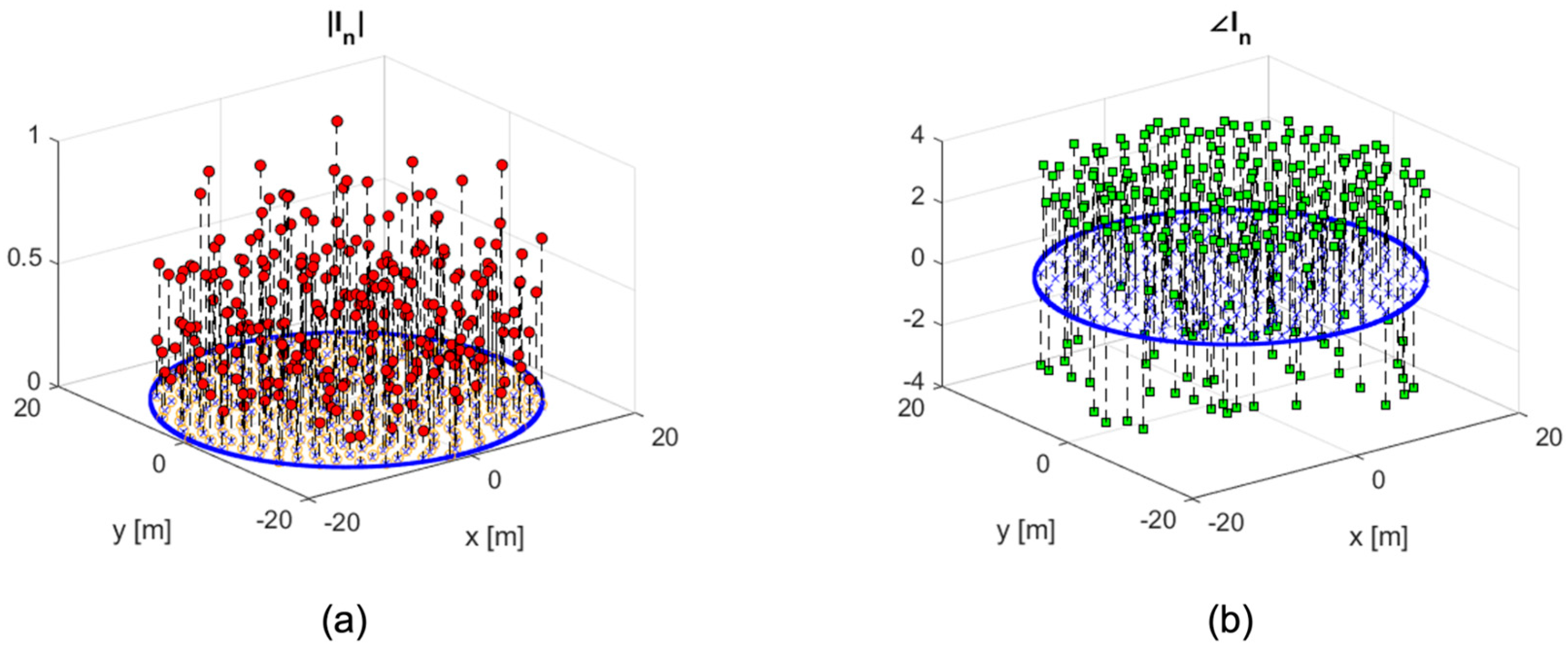
To address this, the convex optimization approach was implemented using MATLAB’s
fmincon solver with the Active-Set algorithm. The resulting complex weight coefficients, including both amplitude and phase, are shown in
Figure 7, alongside the geometric distribution of the antenna elements.
Following optimization, the synthesized radiation pattern,
Figure 6b, demonstrates a substantial improvement in sidelobe performance. The Peak Sidelobe Level (PSL) was reduced from −14.6 dB in the uniform case to −18.2 dB, representing an improvement of approximately 3.6 dB. Notably, this enhancement was achieved without degradation of the main beam. Both the HPBW and the null-to-null beamwidth remained consistent at approximately ±0.62° and ±1.5°, respectively, for both configurations. Furthermore,
Figure 6c presents a comparison between the radiation pattern at φ = 197° for unitary and optimized element weights. This cut, representing the worst-case scenario in terms of PSL, confirms that the sidelobe reduction does not adversely affect the main lobe of the antenna array’s radiation pattern.
To provide a more comprehensive performance metric, the Integrated Sidelobe Ratio (ISR), computed over the entire radiation sphere, was employed. This well-established metric is defined as follows:
ISR quantifies the ratio of total radiated power in the sidelobe region to that within the main lobe. As such, it provides a more holistic assessment of the pattern quality, particularly under the assumption of isotropic radio frequency noise, where the overall sidelobe suppression is more critical than peak values alone.
Using this metric, the ISR improved from −11.45 dB before the optimization to −13.57 dB after optimization. The 2.12 dB improvement in ISR confirms that the proposed synthesis technique effectively reduces the total sidelobes’ energy across all directions, providing an improved signal-to-noise ratio performance in noise-affected radio astronomy environments.
Table 1 summarizes the key performance metrics for the two excitation strategies. The only notable trade-off observed was a slight reduction in directivity, from 32.2 dB in the uniform case to 30.1 dB with optimized weights. This reduction is consistent with expectations, as the optimization redistributes energy to suppress sidelobes, slightly broadening the energy footprint of the main lobe.
Overall, the obtained results confirm the effectiveness of the proposed synthesis framework in improving the radiation characteristics of SKA-Low stations. The significant reduction in sidelobe levels, achieved without compromising beamwidth or introducing beam distortion, is particularly advantageous for radio astronomy applications. The improved sidelobe suppression achieved here enhances the station’s dynamic range, mitigates susceptibility to radio frequency interference, and contributes to more accurate sky imaging and calibration.
Furthermore, the minimal loss in directivity suggests that the trade-off between main lobe gain and sidelobe suppression is well-balanced. This demonstrates the robustness of the optimization method, especially considering the constraints imposed by the physical layout and electromagnetic behavior of real-world antenna systems.
In conclusion, the presented synthesis methodology provides a scalable and effective solution for large-scale array calibration, and its application to next-generation radio telescopes such as the SKA can support the stringent performance requirements demanded by deep-space observation missions.
Furthermore, to complement the scalability claim, we have considered the computational features of the proposed optimization strategy. The convex formulation ensures consistent convergence even with large-scale arrays, such as the 256-element SKA-Low station examined in this work. Nonetheless, as the array size increases, both memory requirements and solver runtime naturally grow with the problem dimensionality. These effects remain manageable in the current framework (which can be integrated by dedicated numerical strategies and parallelized solvers) for future deployments involving even larger configurations. Therefore, by virtue of its adaptability to increasingly complex radio telescope systems, the proposed method also has a relevant practical scope.
5. Conclusions and Future Perspectives
This work presents a convex optimization-based methodology aimed at enhancing the electromagnetic performance of Square Kilometer Array (SKA) Low-Frequency stations employing fixed Vogel-pattern array configurations.
The proposed framework was designed to suppress sidelobes while maintaining key main beam characteristics, using a constrained optimization approach that ensures globally optimal solutions with manageable computational complexity, an important advantage for large-scale aperture arrays. This ensures the effectiveness of the antenna synthesis algorithm in overcoming critical performance challenges inherent to low-frequency radio telescopes such as those in the SKA.
Numerical evaluations, conducted using realistic embedded element patterns at 350 MHz, demonstrated a 3.6 dB reduction in the peak sidelobe level when compared to the uniform excitations case. Crucially, this improvement was achieved without altering the array geometry or degrading the main beam shape. In particular, both the Half Power Beamwidth and the null-to-null beamwidth remained unchanged. Although the directivity experienced a reduction (from 32.2 dB to 30.1 dB), this trade-off reflects the intentional redistribution of energy from the sidelobes into broader angular regions as part of the sidelobe suppression strategy.
To provide a more comprehensive and objective assessment of performance, the Integrated Sidelobe Ratio (ISR) was employed as an additional evaluation metric. The ISR, which quantifies the ratio of total radiated power in the sidelobe region to that within the main lobe, improved from −11.45 dB before the optimization to −13.57 dB after the optimization. This 2.12 dB improvement in the ISR confirms that the proposed synthesis technique reduces the total sidelobes’ energy across the full radiation sphere, providing improved signal-to-noise ratio performance in noise-affected environments such as radio astronomy.
A key strength of this approach lies in its generalizability. In fact, it can be adapted to different frequencies and array configurations, supporting flexible and scalable beamforming strategies. Additionally, this foundation enables future advancements, including multi-frequency and wideband optimization, as well as adaptive weighting techniques tailored for dynamic observation conditions.
The methodology presented in this work can serve as a foundational tool to support future experimental developments related to SKA-Low. In fact, by enabling the computational identification of potential performance limitations or synthesis errors, it can guide the re-weighting or re-design of antennas prior to field validation. This form of pre-assessment is particularly valuable given the scale and complexity of SKA-Low systems. Future research, to be pursued within the framework of the upcoming SKA international project, will focus on integrating the proposed synthesis methods with experimental validation campaigns. These efforts aim to develop practical calibration strategies and exploring reconfigurable weighting schemes, ultimately enhancing the system-level performance and reliability through a combined numerical–experimental approach.
In summary, this work marks a significant advancement toward intelligent and scalable design methodologies for next-generation radio telescope arrays.
Author Contributions
G.M.B.: conceptualization, methodology, validation, formal analysis, investigation, writing—original draft preparation, writing—review and editing. G.C.: conceptualization, methodology, validation, formal analysis, investigation, writing—original draft preparation, writing—review and editing. P.B.: conceptualization, methodology, investigation, writing—original draft preparation, writing—review and editing. M.G.L.: conceptualization, methodology, investigation, writing—original draft preparation. R.P.: conceptualization, methodology, validation, writing—original draft preparation. A.F.M.: conceptualization, methodology, validation, writing—original draft preparation, writing—review and editing, project administration, funding acquisition. All authors have read and agreed to the published version of the manuscript.
Funding
This research was funded in part by the European Union under the Italian National Recovery and Resilience Plan (NRRP) of NextGenerationEU, partnership on “Telecommunications of the Future” (PE00000001—program “RESTART”), and in part by “MEETAPP—MEtasurface-based tEchnology Towards industrial APPlications” (PRIN2022 P2022ZZ8APA).
Institutional Review Board Statement
Not applicable.
Informed Consent Statement
Not applicable.
Data Availability Statement
The raw data supporting the conclusions of this article will be made available by the authors on request.
Acknowledgments
Authors gratefully thank Tommaso Isernia for fruitful discussions. They also extend their sincere thanks to ICRAR-Curtin, Australia, where the EEPs dataset used in this study was computed.
Conflicts of Interest
The authors declare no conflicts of interest.
Abbreviations
The following abbreviations are used in this manuscript:
| AAVS | Aperture Array Verification System |
| CP | Convex Programming |
| EEP | Embedded Element Pattern |
| HPBW | Half Power BeamWidth |
| ISR | Integrated Sidelobe Ratio |
| LP | Linear Programming |
| PSL | Peak Sidelobe Level |
| SLL | Sidelobe Level |
| SKA | Square Kilometer Array |
| SKALA | Square Kilometer Array Log-periodic Antenna |
| SKAO | Square Kilometer Array Observatory |
| UB | Upper Bound |
References
- Labate, M.G.; Wagg, J.; Alachkar, B.; Breen, S.; Swart, G.; van Es, A. The most sensitive radio telescope to deliver unprecedented and global open science: The Square Kilometer Array (50 MHz–15.3 GHz). In Proceedings of the 15th European Conference on Antennas and Propagation (EuCAP), Dusseldorf, Germany, 22–26 March 2021; pp. 1–5. [Google Scholar] [CrossRef]
- Braun, R.; Bourke, T.L.; Green, J.A.; Keane, E.; Wagg, J. Advancing astrophysics with the square kilometre array. In Proceedings of the Advancing Astrophysics with the Square Kilometre Array (AASKA14), Giardini Naxos, Italy, 9–13 June 2014; Volume 215, p. 174. [Google Scholar]
- Labate, M.G.; Waterson, M.; Swart, G.; Bowen, M.; Dewdney, P. The Square Kilometre Array Observatory. In Proceedings of the IEEE International Symposium on Antennas and Propagation and USNC-URSI Radio Science, Atlanta, GA, USA, 7–12 July 2019; pp. 391–392. [Google Scholar] [CrossRef]
- Thompson, A.R.; Moran, J.M.; Swenson, G.W. Interferometry and Synthesis in Radio Astronomy; Springer Nature: Berlin/Heidelberg, Germany, 2017; p. 872. [Google Scholar]
- Roy, J.; Pleasance, M.; Harrison, S.; Wolfgang, A.; Caputa, K. Overview of the Single Pixel Feed Receiver System of Square Kilometer Array MID Telescope. In Proceedings of the 3rd URSI Atlantic and Asia Pacific Radio Science Meeting (AT-AP-RASC), Gran Canaria, Spain, 30 May–4 June 2022; pp. 1–4. [Google Scholar] [CrossRef]
- Bolli, P.; Mezzadrelli, L.; Monari, J.; Perini, F.; Tibaldi, A.; Virone, G. Test-Driven Design of an Active Dual-Polarized Log-Periodic Antenna for the Square Kilometre Array. IEEE Open J. Antennas Propag. 2020, 1, 253–263. [Google Scholar] [CrossRef]
- Bolli, P.; Bercigli, M.; Di Ninni, P.; Mezzadrelli, L.; Virone, G. Impact of mutual coupling between SKALA4. 1 antennas to the spectral smoothness response. J. Astron. Telesc. Instrum. Syst. 2022, 8, 011023. [Google Scholar] [CrossRef]
- Bolli, P.; Davidson, D.B.; Braun, R.; Di Ninni, P.; Ung, D. Evaluating an alternate layout for the SKA-Low aperture array stations using Computational Electromagnetic simulations. In Proceedings of the International Conference on Electromagnetics in Advanced Applications (ICEAA), Cape Town, South Africa, 5–9 September 2022; pp. 200–205. [Google Scholar] [CrossRef]
- Wayth, R.B.; Davidson, D.; Ung, D. Aperture efficiency of beamforming with mutual coupling in SKA-Low stations. In Proceedings of the XXXVth General Assembly and Scientific Symposium of the International Union of Radio Science (URSI GASS), Sapporo, Japan, 19–26 August 2023; pp. 1–4. [Google Scholar] [CrossRef]
- Davidson, D.B.; Wyath, R.B.; Ung, D. Evaluation of alternative SKA-Low station layouts. In Proceedings of the XXXVth General Assembly and Scientific Symposium of the International Union of Radio Science (URSI GASS), Sapporo, Japan, 19–26 August 2023; pp. 1–4. [Google Scholar] [CrossRef]
- Anstey, D.; Cumner, J.; Gueuning, Q.; O’Hara, O.; de Lera Acedo, E.; Brown, A. Mitigating Zenith Blindness from Mutual Coupling in a Sunflower Phased Array. In Proceedings of the 18th European Conference on Antennas and Propagation (EuCAP), Glasgow, UK, 17–22 March 2024; pp. 1–5. [Google Scholar] [CrossRef]
- Isernia, T.; Panariello, G. Optimal focusing of scalar fields subject to arbitrary upper bounds. Electron. Lett. 1998, 34, 162–164. [Google Scholar] [CrossRef]
- Bucci, O.M.; Caccavale, L.; Isernia, T. Optimal far-field focusing of uniformly spaced arrays subject to arbitrary upper bounds in nontarget directions. IEEE Trans. Antennas Propag. 2002, 50, 1539–1554. [Google Scholar] [CrossRef]
- Isernia, T.; Di Iorio, P.; Soldovieri, F. An effective approach for the optimal focusing of array fields subject to arbitrary upper bounds. IEEE Trans. Antennas Propag. 2000, 48, 1837–1847. [Google Scholar] [CrossRef]
- Battaglia, G.M.; Morabito, A.F.; Palmeri, R.; Isernia, T. Constrained focusing of vector fields intensity in near zone and/or complex scenarios as a low-dimensional global optimization. J. Electromagn. Waves Appl. 2020, 34, 1977–1989. [Google Scholar] [CrossRef]
- Battaglia, G.M.; Bellizzi, G.G.; Morabito, A.F.; Sorbello, G.; Isernia, T. A general effective approach to the synthesis of shaped beams for arbitrary fixed-geometry arrays. J. Electromagn. Waves Appl. 2019, 33, 2404–2422. [Google Scholar] [CrossRef]
- Battaglia, G.M.; Morabito, A.F.; Sorbello, G.; Isernia, T. Mask-Constrained Power Synthesis of Large and Arbitrary Arrays as a Few-Samples Global Optimization. Prog. Electromagn. Res. C 2020, 98, 69–81. [Google Scholar] [CrossRef]
- Bucci, O.M.; D’Urso, M.; Isernia, T. Optimal synthesis of difference patterns subject to arbitrary sidelobe bounds by using arbitrary array antennas. IEE Proc.-Microw. Antennas Propag. 2005, 152, 129–137. [Google Scholar] [CrossRef]
- Palmeri, R.; Battaglia, G.M.; Morabito, A.F.; Costanzo, S.; Venneri, F.; Isernia, T. Fault Diagnosis of Realistic Arrays From a Reduced Number of Phaseless Near-Field Measurements. IEEE Trans. Antennas Propag. 2023, 71, 7206–7219. [Google Scholar] [CrossRef]
- Battaglia, G.M.; Morabito, A.F.; Palmeri, R.; Isernia, T. Effective Non-Iterative Phase Retrieval of 2-D Bandlimited Signals with Applications to Antenna Characterization and Diagnostics. IEEE Trans. Antennas Propag. 2023, 71, 6444–6453. [Google Scholar] [CrossRef]
- Liu, Y.; Huang, X.; Xu, K.D.; Song, Z.; Yang, S.; Liu, Q.H. Pattern Synthesis of Unequally Spaced Linear Arrays Including Mutual Coupling Using Iterative FFT via Virtual Active Element Pattern Expansion. IEEE Trans. Antennas Propag. 2017, 65, 3950–3958. [Google Scholar] [CrossRef]
- Bolli, P.; Davidson, D.B.; Bercigli, M.; Di Ninni, P.; Labate, M.G.; Ung, D.; Virone, G. Computational electromagnetics for the SKA-Low prototype station AAVS2. J. Astron. Telesc. Instrum. Syst. 2022, 8, 011017. [Google Scholar] [CrossRef]
- Altair, FEKO, Suite 2018. Available online: www.feko.info (accessed on 21 May 2025).
- Autodesk, AutoCAD. 2019. Available online: https://altairhyperworks.com/product/FEKO/ (accessed on 21 May 2025).
- Steiner, R.; Ung, D.C.; Hubrechsen, A.; Jones, R.D.; Wayth, R.B.; Bentum, M.J.; Smolders, A.B. Optimizing processing time of radio-astronomy antenna simulations using FEKO. Appl. Comput. Electromagn. Soc. J. (ACES) 2020, 35, 1153–1160. [Google Scholar] [CrossRef]
- Bucci, O.M.; Gennarelli, C.; Savarese, C. Representation of electromagnetic fields over arbitrary surfaces by a finite and nonredundant number of samples. IEEE Trans. Antennas Propag. 1998, 46, 351–359. [Google Scholar] [CrossRef]
- Ludwig, A. The definition of cross polarization. IEEE Trans. Antennas Propag. 1973, 21, 116–119. [Google Scholar] [CrossRef]
| Disclaimer/Publisher’s Note: The statements, opinions and data contained in all publications are solely those of the individual author(s) and contributor(s) and not of MDPI and/or the editor(s). MDPI and/or the editor(s) disclaim responsibility for any injury to people or property resulting from any ideas, methods, instructions or products referred to in the content. |
© 2025 by the authors. Licensee MDPI, Basel, Switzerland. This article is an open access article distributed under the terms and conditions of the Creative Commons Attribution (CC BY) license (https://creativecommons.org/licenses/by/4.0/).


 ,
, 


