Featured Application
This study provides both clinical and biomechanical insights into the optimization of upper molar distalization using clear aligners. By analyzing the effects of attachment types and trimline lengths through finite element analysis, the findings may assist orthodontists in selecting more effective configurations for achieving controlled tooth movement, while also guiding aligner manufacturers in improving force delivery systems.
Abstract
Upper molar distalization using clear aligners requires optimal force direction and control to ensure effective and predictable tooth movement. This study aimed to evaluate the biomechanical effects of different aligner trimline lengths (trimline ending at the gingival margin vs. 2 mm extended) and attachment designs (no attachment, vertical rectangular, 25-degree beveled vertical, and double horizontal) on maxillary first molar distalization using finite element analysis. A three-dimensional maxillary model was constructed from CBCT data, and eight different aligner configurations were simulated under identical distalizing force. The stress distribution within the periodontal ligament of the maxillary first molar and displacement of crown and root landmarks in three axes were analyzed. The models with no attachments and trimlines ending at the gingival margin exhibited the highest degree of uncontrolled tipping and uneven stress distribution. In contrast, models combining extended trimlines with either beveled vertical or double horizontal attachments demonstrated more controlled bodily movement, reduced palatal root mesial displacement, and more uniform vertical movement. Overall, extended trimlines were associated with increased total distalization and improved force transmission. These findings provide biomechanical insight into optimizing aligner configuration for upper molar distalization and may guide clinicians and manufacturers in improving treatment precision and predictability.
1. Introduction
Dental Class II malocclusions without skeletal discrepancies are often associated with maxillary dentoalveolar protrusion and/or mesial migration of the maxillary first molars [1]. Contributing factors may include premature loss of the second primary molar, interproximal caries, or congenital tooth agenesis, which can lead to mesial molar displacement, resulting in arch length reduction, space deficiency, and crowding [1,2].
Among various space-gaining strategies, maxillary molar distalization remains a widely used and effective approach that improves both molar relationships and arch length [3,4,5,6]. In recent years, clear aligners have gained popularity as an alternative to traditional appliances for molar distalization due to their improved aesthetics, comfort, and enhanced patient compliance [7]. However, the biomechanics involved in achieving effective distalization with aligners remain a subject of ongoing investigation.
Studies have demonstrated that upper molar distalization with aligners is feasible and effective, especially when combined with composite attachments or auxiliary devices like buttons to improve movement control [7,8,9,10]. However, such distalization may also induce unwanted vertical and transverse displacements, compromising treatment outcomes [11]. While various biomechanical strategies have been developed to counteract these effects in fixed appliances, limited research has explored similar approaches in aligner therapy [7,8,9].
Finite element analysis (FEA) is a computational technique employed to evaluate stress distribution and deformation in complex structures. FEA has been extensively applied in orthodontic research to analyze the biomechanics of clear aligners, particularly in assessing the effects of varying aligner thicknesses and attachment configurations [12,13,14,15]. Despite its broad application, limited studies have utilized FEA to examine upper molar distalization with clear aligners, and most existing studies have focused on a narrow set of attachment types and trimline designs [10,16,17]. To date, no study has systematically evaluated the combined effects of varying aligner trimline lengths and attachment designs on upper molar distalization.
Previous research suggests that increasing aligner trimline length enhances tooth movement control and improves aligner retention [10,16,17]. Moreover, studies analyzing tooth movement with clear aligners highlight the crucial role of attachments in force distribution and movement predictability [18,19,20].
Thus, this study aims to investigate the biomechanical effects of different attachment designs and aligner trimline lengths on upper molar distalization, using finite element analysis.
2. Materials and Methods
2.1. Simulation Model Development
A maxillary bone model was developed using cone beam computed tomography (CBCT) data from a healthy adult patient with no craniofacial anomalies. CBCT images were acquired using a Planmeca ProMax 3D Mid system (Planmeca, Helsinki, Finland) with a slice thickness of 0.1 mm and were retrieved from the archives of the Department of Radiology, Faculty of Dentistry, Ankara Yıldırım Beyazıt University. The DICOM data were segmented in 3D Slicer software (version 4.11.20210226, available at https://www.slicer.org, accessed on 15 September 2023) to create a three-dimensional anatomical model, which was exported in STL format for finite element analysis (FEA).
The model included all maxillary teeth from the right second molar to the left second molar. The periodontal ligament (PDL) was modeled as a 0.2 mm layer between the roots and the surrounding alveolar bone. Gingival mucosa was generated by projecting the outer surface of the cortical bone. Two aligner geometries were designed: the first featured a trimline ending at the gingival margin, while the second had a trimline extending 2 mm above the gingiva. Both aligners were modeled with a uniform thickness of 0.5 mm, consistent with previous studies [14,17].
All components—including teeth, cortical bone, gingiva, aligners, and attachments—were assumed to be homogeneous, isotropic, and linearly elastic materials. The mechanical properties assigned to these materials are summarized in Table 1 [15,21]. In contrast, the PDL was modeled as a nonlinear hyperelastic material using a second-order Ogden constitutive model, which more accurately reflects the physiological behavior of soft periodontal tissues under orthodontic forces [16,22,23,24]. The material parameters employed in the Ogden model were based on values previously reported by Wu et al. [22]. Specifically, the model incorporated two terms with corresponding constants: μ1 = 0.00554 MPa, α1 = 0.25, and μ2 = 0.11 MPa, α2 = 0.1153. Additionally, the compressibility parameters were defined as D1 = 0.1216 MPa and D2 = 0.97 MPa. These constants were used to simulate the nonlinear mechanical behavior of periodontal tissues in the finite element model. However, time-dependent viscoelastic properties of the PDL were not incorporated into the model.

Table 1.
Material properties.
A nonlinear static analysis was performed using the implicit solver in LS-DYNA. The primary source of nonlinearity in this analysis stemmed from the material models. However, additional factors such as geometric and contact nonlinearities may also have contributed to the overall nonlinear behavior of the system.
Four finite element models were generated based on the type and placement of attachments on the upper first and second molars. These models included the following: no attachment (NA), a vertical attachment (VA), a 25° angled vertical attachment (25VA), and a double horizontal attachment (DHA). Additionally, two trimline configurations were considered: the M0 group featured a trimline ending at the gingival margin, while the M2 group included a trimline extending 2 mm above the gingiva. This design matrix resulted in a total of eight models (Figure 1).
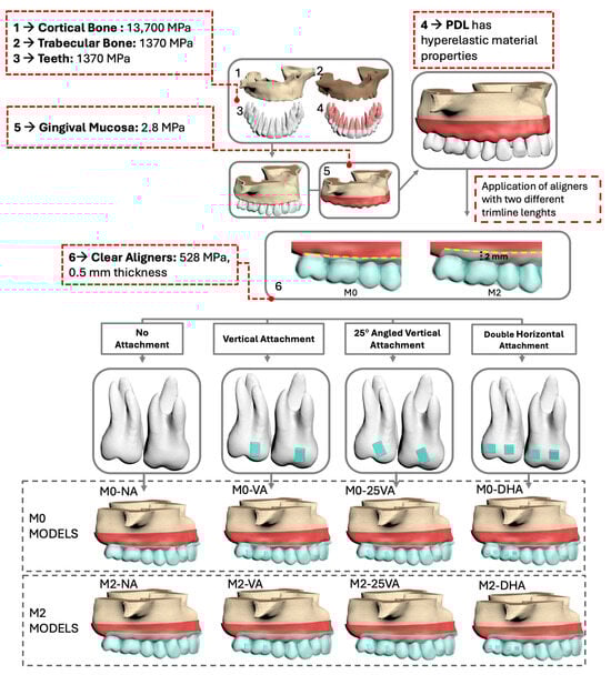
Figure 1.
Finite element modeling process of the eight experimental models.
Vertical and 25° angled vertical attachments were modeled as single rectangular blocks with dimensions of 3 × 2 × 1 mm, consistent with typical clinical designs reported in recent finite element studies [10,14]. Double horizontal attachments were modeled as two individual blocks per tooth (placed mesially and distally), each measuring 2 × 2× 1 mm to accommodate the buccal surface anatomy of molars. All attachments were assumed to behave as rigid bodies, given the high stiffness of composite resin materials.
2.2. Meshing and Analysis Settings
All models were meshed using 4-node tetrahedral elements in ANSYS Workbench (version 2023 R1, Ansys Inc., Canonsburg, PA, USA; available at https://www.ansys.com, accessed on 15 September 2023) and exported to LS-DYNA (version R11.1.0, Livermore Software Technology Corporation, Livermore, CA, USA; available at https://www.lstc.com, accessed on 30 September 2023) for nonlinear static analysis using an implicit solver (Table A1). Frictional contacts (coefficient of friction µ = 0.2) were defined between the aligner and both the tooth surfaces and attachments. All other interfaces were modeled as bonded.
2.3. Loading and Boundary Conditions
The base of the maxillary model was constrained in all directions to simulate fixation. Boundary conditions were applied perpendicular to the X-axis and symmetrically along the Y-Z plane. The coordinate system was defined as follows:
- X-axis: Bucco-palatal direction (+palatal, −buccal);
- Y-axis: Mesio-distal direction (+distal, −mesial);
- Z-axis: Occluso-gingival direction (+gingival, −occlusal).
A 0.25 mm distal displacement was applied to the right maxillary first and second molars to simulate aligner-induced force during distalization. Eight nonlinear simulations were performed—one for each model configuration. Von Mises stress distribution within the PDL of the first molar and displacements of anatomical landmarks were recorded for all three axes.
The following measurement points were analyzed:
- Crown landmarks: Mesiobuccal cusp tip (MBCT), distobuccal cusp tip (DBCT), mesiopalatal cusp tip (MPCT), and distopalatal cusp tip (DPCT).
- Root landmarks: Mesiobuccal root apex (MBRA), distobuccal root apex (DBRA), and palatal root apex (PRA).
2.4. Ethical Approval
This study was approved by the Ankara Yıldırım Beyazıt University Health Sciences Ethics Committee (Approval No: 2022-1105). No patient-identifiable data were used.
3. Results
3.1. Stress Distributions in the Periodontal Ligament
Von Mises stress distribution varied across models (Figure 2). The highest stress intensity was observed in the M2-NA model (0.312 MPa), while the lowest occurred in the M2-DHA model (0.241 MPa). Models without attachments (M0-NA and M2-NA) exhibited more apically concentrated stress zones. Attachment-equipped models showed more homogeneous stress distribution across the PDL, especially in the 25VA and DHA groups.
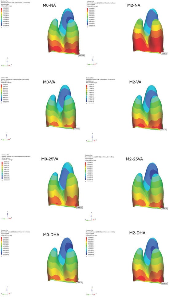
Figure 2.
Von Mises stress distributions in the PDL of the maxillary first molar.
3.2. Displacement Along the X-Axis (Bucco-Palatal Direction)
Displacement was evaluated along all three axes based on the displacement data collected from the selected reference points on the maxillary first molar. Additionally, the homogeneity of the displacement color distribution was assessed to analyze the uniformity of movement patterns.
In the M0 models, the greatest buccal crown displacement along the X-axis was observed in the M0-NA model (MBCT: −0.099 mm), while the smallest displacement occurred in the M0-25VA model (MBCT: −0.048 mm). Conversely, the largest buccal root movement was recorded in M0-25VA (MBRA: −0.069 mm).
In the M2 models, the highest buccal crown displacement on the X-axis was found in the M2-NA model (MBCT: −0.112 mm), whereas M2-VA and M2-25VA exhibited reduced crown movement (M2-VA: −0.071 mm, M2-25VA: −0.080 mm). Regarding root movement, the greatest buccal root displacement was observed in M2-NA (DBRA: −0.002 mm) (Figure 3).
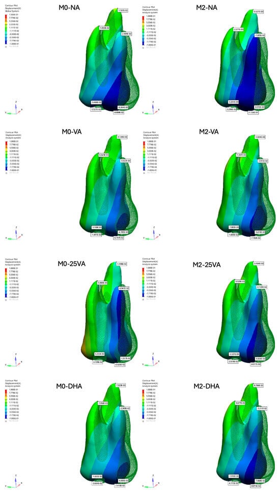
Figure 3.
Displacement results of the maxillary first molar along the X-axis.
3.3. Displacement Along the Y-Axis (Mesio-Distal Direction)
Along the Y-axis, in the M0 models, the difference between crown and root displacement was more pronounced in M0-NA compared to the other models, reflecting an imbalance between crown and root movement (Figure 3). Additionally, in all models, the palatal root tip (PRA) exhibited mesial displacement, contrary to the expected distal movement. M0-NA demonstrated the greatest mesial displacement of the palatal root tip (PRA: 0.0116 mm), indicating uncontrolled tipping. In contrast, the least mesial displacement of the palatal root tip was observed in M0-DHA (PRA: −0.01496 mm).
In the M2 models, all cases exhibited mesial displacement of the palatal root tip along the Y-axis, with the M2-VA model showing the highest mesial movement (PRA: 0.00412 mm) (Figure 4).
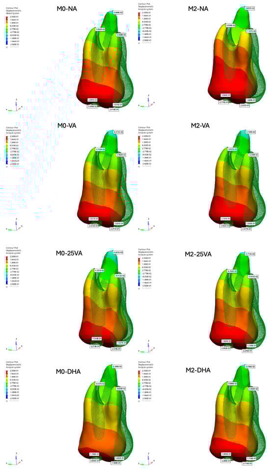
Figure 4.
Displacement results of the maxillary first molar along the Y-axis.
3.4. Displacement Along the Z-Axis (Occluso-Gingival Direction)
Along the Z-axis, in the M0-25VA model, vertical displacement was evenly distributed across all surfaces of the maxillary first molar, indicating more uniform movement (MBCT: −0.04824 mm; DBCT: −0.02729 mm). In contrast, the M0-NA model exhibited non-uniform vertical displacement, with variations across different tooth surfaces (MBCT: −0.09909 mm; DBCT: −0.05527 mm).
In the M2 models, vertical displacement was more homogeneously distributed across all surfaces of the maxillary first molar in the M2-25VA and M2-DHA models, indicating improved vertical control (M2-25VA: MBCT: −0.08077 mm, DBCT: −0.02619 mm; M2-DHA: MBCT: −0.07410 mm, DBCT: −0.03604 mm) (Figure 5).
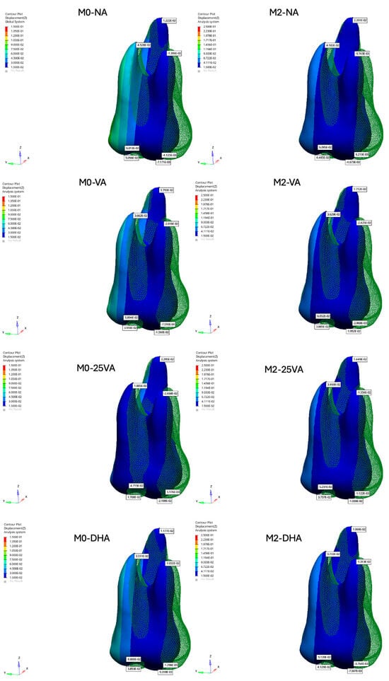
Figure 5.
Displacement results of the maxillary first molar along the Z-axis.
3.5. Rotational Displacement
All models exhibited mesio-palatal rotation. The greatest rotational tendency was observed in the M0-NA model, with notable buccal displacement at the mesiobuccal cusp (MBCT: –0.099 mm), whereas the M2-DHA model showed the least displacement (MBCT: –0.074 mm) (Figure 3).
4. Discussion
Finite element analysis has been widely used in orthodontic research to evaluate the biomechanics of clear aligners, particularly regarding aligner geometry and attachment design. However, its application in upper molar distalization remains limited, with most studies addressing only a narrow range of trimline lengths and attachment types. Therefore, the effects of different trimline heights, attachment orientations, and aligner thicknesses on molar movement mechanics are still not fully understood [10,12,16,17].
The periodontal ligament is critical in orthodontic force transmission [22]. Traditional FEA models typically represent the PDL as a linear elastic material [14,15], which may oversimplify its actual biomechanical behavior [21]. In this study, a second-order Ogden hyperelastic model was used to more accurately replicate PDL physiology [22]. Although Cattaneo et al. [25] argued that nonlinear modeling may be less critical during the initial phase of tooth movement, using an advanced material model enhances the realism of soft tissue response [13,23]. Nevertheless, the lack of standardized experimental data on PDL properties continues to limit model consistency [23].
Although von Mises stress is commonly used to assess force distribution, it cannot distinguish between tensile and compressive stresses in anisotropic tissues like the PDL. Therefore, complementary methods, such as principal or hydrostatic stress analysis, may enhance simulation accuracy [22].
Studies have compared aligner thicknesses of 0.3 mm [15,16], 0.5 mm [14,17,26], and 0.75 mm [10,27] with 0.5 mm, showing the most efficient performance based on micro-CT data [14,17]. Accordingly, the present study modeled the aligner with a 0.5 mm thickness. Nonetheless, clinicians should consider potential material degradation over time, which may reduce force transmission efficiency [28].
Aligner trimline design is another factor that affects treatment outcomes [19,20]. Scalloped and straight edges are commonly used, with trimlines ending at or 2 mm above the gingival margin. Extended trimlines generally offer improved crown engagement and mechanical control [19,20]. Traversa et al. [29] reported that flat trimlines enhance translational control, while Gao et al. [18] observed stronger forces with extended designs compared to gingival-level trimlines. These findings highlight the relevance of trimline configuration in clinical planning.
Conventional rectangular attachments with uniform dimensions are commonly preferred for molar distalization [14,16,17]. However, the present findings suggest that variations in attachment geometry may affect tooth displacement patterns.
4.1. Stress Distribution and Attachment Effects
Models without attachments (M0-NA and M2-NA) showed higher instability, as reflected in greater stress variation within the PDL. Increasing trimline length shifted stress apically, likely due to extended gingival coverage. Attachment shape had minimal impact on von Mises stress distribution.
Ayidağa and Kamiloğlu [16] reported that horizontal attachments offer more uniform stress distribution in the PDL during molar distalization. Their model, however, used 0.15 mm displacement and a 0.25 mm PDL space, while ours applied 0.25 mm displacement and a 0.20 mm PDL space. These differences may account for the variation in stress patterns.
4.2. Displacement Patterns
All models demonstrated buccal inclination along the X-axis, consistent with previous findings on the limited root control of aligners [30,31]. M0-25VA and M2-25VA minimized bucco-palatal tipping most effectively, while M0-NA showed the greatest tipping. All models showed distal rotation, with greater buccal displacement on the mesial side. As mesio-palatal rotation is common in Class II cases [32,33], this pattern may provide beneficial derotation as a secondary effect.
Rotational control is particularly difficult in conical teeth such as premolars and canines [34,35]. Although rotation was not directly targeted, consistent distopalatal rotation was observed across all models, suggesting that distalization with aligners—regardless of attachment presence—may contribute to improving Class II molar relationships.
Distal tipping occurred in all models along the Y-axis. In M0 models, M0-NA had the most mesial root movement, indicating poor root control, while M0-DHA showed the most favorable movement pattern. This aligns with the assumption that double horizontal attachments offer improved root anchorage. Saif et al. [36] showed that 2–3 mm of distalization is achievable with aligners, but attachments did not significantly affect the amount of movement. Notably, their study did not assess side effects like tipping or rotation. In our study, M2 models achieved more distalization than M0 models, supporting Elshazly et al. [20], who found that longer trimlines improved third-order (root) control. Although our FEA simulation revealed consistent tipping across all configurations, Mamani et al. [37] reported variable tipping behavior in clinical cases, with first molars showing less and second molars showing more distal tipping than planned. This highlights how biomechanical interactions—such as force application height and anterior retraction phases—may differentially affect tipping expression across molars.
Vertical (Z-axis) displacement was observed in all models, consistent with distal tipping. Caruso et al. [38] reported no vertical dimension loss in clinical cases, in contrast to our findings. However, a recent systematic review and meta-analysis by Park et al. [39] concluded that although clear aligners may produce slight molar intrusion, no clinically significant vertical skeletal changes were observed. This discrepancy highlights the influence of evaluation methods—such as lateral cephalometry versus FEA modeling—and the need for cautious interpretation in the absence of occlusal loading.
Finally, trimline length influenced the homogeneity of surface displacement. Longer trimlines resulted in more consistent tooth surface movement, echoing findings by Traversa et al. [29]. M2-25VA and M2-DHA showed the most balanced distribution, while M0-NA had the most uneven displacement. Ayidağa and Kamiloğlu [16] similarly found that horizontal attachments improved occluso-gingival control.
The focus on the maxillary first molar reflects its pivotal role in orthodontic treatment and occlusion. As noted by Andrews [40], this tooth is critical for establishing normal occlusion and stabilizing the posterior arch. Serving as a primary anchorage unit, it influences the movement of adjacent teeth, particularly during distalization. Prior studies have emphasized the need for precise control of this tooth’s position. Lamons and Holmes [34] addressed the challenges posed by its rotation, while Bolla et al. [2] highlighted its tendency for mesial drift, underscoring the importance of maintaining its position for treatment success.
Similar to Andrews’ [40] three-dimensional evaluation of molar positioning, this study focused on the maxillary first molar in three dimensions. This approach offers a more comprehensive understanding of its movement and interaction with aligner mechanics, enabling more precise distalization. Stoller [41] also emphasized the importance of this tooth’s position in occlusion, noting that minor deviations can affect interdigitation and overall arch balance, further supporting its selection for detailed analysis.
4.3. Clinical Implications
This finite element analysis study highlights several biomechanical tendencies related to aligner design in upper molar distalization. Configurations using extended trimlines combined with angled or double horizontal attachments exhibited more balanced movement in terms of root positioning and tipping control. Although these findings are based solely on simulations, they suggest that careful planning of attachment geometry and aligner edge design may enhance clinical performance and predictability. These results may be particularly relevant for clinicians managing molar distalization in Class II cases.
4.4. Limitations and Future Directions
One key limitation of this study is the material assumptions used in the finite element model. All structures—excluding the PDL—were modeled as homogeneous, isotropic, and linearly elastic materials for computational simplicity. While this approach is commonly applied in FEA studies, it does not fully capture the nonlinear and anisotropic behavior of biological tissues. In addition, the PDL was modeled as a nonlinear hyperelastic material to simulate its immediate mechanical response. However, its viscoelastic behavior—characterized by stress relaxation and creep under sustained loading—was not included. This may limit the accuracy of predictions regarding long-term tooth movement [23]. Future studies should incorporate viscoelastic PDL modeling to better approximate biological conditions [42].
Moreover, a uniform aligner thickness of 0.5 mm was assumed in the model. However, this does not reflect the variable thickness introduced by thermoforming in clinical settings, where commercial aligners typically range between 0.6 and 0.75 mm. In addition, the time-dependent mechanical behavior of thermoplastic aligners—such as stress relaxation and material creep—was not considered. These dynamic properties may lead to force decay over time and should be incorporated into future models to improve the clinical accuracy of aligner simulations [20,43].
This study is also limited by its simulation-based design. Patient-specific anatomy, soft tissues, and occlusal loads were not included. These may involve clinically relevant variables such as individual differences in bone density, crown height, saliva lubrication, and temperature, which can affect aligner biomechanics in vivo.
Only upper molars were assessed, without evaluating adjacent teeth or anchorage effects. However, clinical studies, such as that of Loberto et al. [44], have demonstrated that maxillary molar distalization with clear aligners can lead to measurable anchorage loss at the premolar and canine levels, particularly in the absence of auxiliary anchorage. The exclusion of anterior segments in our model may thus underestimate the biomechanical impact on the full arch.
Additionally, the influence of aligner wear time, patient compliance, and attachment wear should be examined to improve clinical translation. This study also did not include a staging protocol or simulate sequential tooth movements. Future research should consider time-based staging sequences to reflect the progressive biomechanics of clinical aligner treatment. Moreover, while this study focused on isolated parameters in a controlled simulation, future models may benefit from incorporating clinically oriented guidelines—such as attachment design indications or trimline selection criteria—to enhance practical applicability.
5. Conclusions
This finite element analysis study indicates that both aligner trimline length and attachment design may substantially influence the biomechanics of upper molar distalization. Extended trimlines appeared to improve aligner retention and stress distribution, potentially resulting in increased distal displacement and more controlled root movement. Among the configurations tested, aligners with extended trimlines combined with optimized attachment design tended to promote more balanced and bodily molar movement.
These simulation-based findings suggest that enhancing aligner design through increased coverage and strategic attachment placement may improve the predictability of distalization while minimizing undesired effects such as tipping and mesial root movement. Although patient-specific anatomy and occlusal forces were not included, the model provides useful insights that could inform clinical aligner planning. Further in vivo research is needed to validate these biomechanical observations under clinical conditions.
Author Contributions
Conceptualization, T.B.T. and E.K.; methodology, T.B.T.; validation, E.K. and T.B.T.; investigation, T.B.T.; data curation, T.B.T.; writing—original draft preparation, T.B.T.; writing—review and editing, T.B.T.; visualization, E.K.; supervision, E.K.; project administration, T.B.T. and E.K.; funding acquisition, T.B.T. and E.K. All authors have read and agreed to the published version of the manuscript.
Funding
This study was supported by the Scientific Research Projects Coordination Unit of Ankara Yıldırım Beyazıt University, Türkiye, under project number TDH-2023-2455.
Institutional Review Board Statement
The CBCT scans were obtained from the archives of the Department of Radiology, Faculty of Dentistry, Ankara Yıldırım Beyazıt University. This study was approved by the Ankara Yıldırım Beyazıt University Health Sciences Ethics Committee (Approval No: 2022-1105, Date: 30 September 2022).
Informed Consent Statement
Not applicable.
Data Availability Statement
The data presented in this study are available on request from the corresponding author. The data are not publicly available due to privacy and ethical restrictions.
Acknowledgments
This article is a revised and expanded version of the paper titled “Molar Distalization with Aligners: Which Configuration Should We Use?”, which was originally presented as an oral presentation at the FDI World Dental Congress, held in Istanbul, Türkiye, from 12 to 15 September 2024. The authors extend their sincere gratitude to Tinus Technology for their invaluable assistance in simulation and FEA.
Conflicts of Interest
The authors declare no conflicts of interest.
Abbreviations
The following abbreviations are used in this manuscript:
| FEA | Finite element analysis |
| NA | No attachment |
| VA | Vertical attachment |
| 25VA | 25° angled vertical attachment |
| DHA | Double horizontal attachment |
| M0 | Model with scalloped trimline (0 mm) |
| M2 | Model with extended trimline (2 mm) |
| MBCT | Mesiobuccal cusp tip |
| DBCT | Distobuccal cusp tip |
| MPCT | Mesiopalatal cusp tip |
| DPCT | Distopalatal cusp tip |
| MBRA | Mesiobuccal root apex |
| DBRA | Distobuccal root apex |
| PRA | Palatal root apex |
Appendix A
The number of elements and nodes for each model is listed in Table A1.
Table A1.
Numbers of nodes and elements.
Table A1.
Numbers of nodes and elements.
| Total # of Nodes | Total # of Elements | |
|---|---|---|
| Model 1 | 164,435 | 598,335 |
| Model 2 | 198,100 | 722,605 |
| Model 3 | 200,102 | 728,318 |
| Model 4 | 204,528 | 741,683 |
| Model 5 | 199,771 | 726,917 |
| Model 6 | 200,656 | 727,333 |
| Model 7 | 201,307 | 732,212 |
| Model 8 | 205,092 | 743,064 |
References
- Moyers, R.E.; Riolo, M.L.; Guire, K.E.; Wainright, R.L.; Bookstein, F.L. Differential diagnosis of Class II malocclusions: Part 1. Facial types associated with Class II malocclusions. Am. J. Orthod. 1980, 78, 477–494. [Google Scholar] [CrossRef] [PubMed]
- Bolla, E.; Muratore, F.; Carano, A.; Bowman, S.J. Evaluation of maxillary molar distalization with the distal jet: A comparison with other contemporary methods. Angle Orthod. 2002, 72, 481–494. [Google Scholar]
- Basdra, E.; Huber, H.; Komposch, G. A clinical report for distalizing maxillary molars by using super-elastic wires. J. Orofac. Orthop. 1996, 57, 118–123. [Google Scholar] [CrossRef]
- Cangialosi, T.J.; Melstrell, M.E., Jr.; Leung, M.A.; Ko, J.Y. A cephalometric appraisal of edgewise Class II nonextraction treatment with extraoral force. Am. J. Orthod. Dentofac. Orthop. 1988, 93, 315–324. [Google Scholar] [CrossRef] [PubMed]
- Enacar, A.; Ozgen, M. Asymmetric maxillary expansion appliance (ABHE). Cleft Palate Craniofac. J. 1993, 30, 416–417. [Google Scholar] [CrossRef]
- Luppanapornlarp, S.; Johnston, L.E., Jr. The effects of premolar-extraction: A long-term comparison of outcomes in “clear-cut” extraction and nonextraction Class II patients. Angle Orthod. 1993, 63, 257–272. [Google Scholar]
- Simon, M.; Keilig, L.; Schwarze, J.; Jung, B.A.; Bourauel, C. Treatment outcome and efficacy of an aligner technique—Regarding incisor torque, premolar derotation and molar distalization. BMC Oral Health 2014, 14, 68. [Google Scholar] [CrossRef]
- Galan-Lopez, L.; Barcia-Gonzalez, J.; Plasencia, E. A systematic review of the accuracy and efficiency of dental movements with Invisalign®. Korean J. Orthod. 2019, 49, 140–149. [Google Scholar] [CrossRef]
- Garino, F.; Castroflorio, T.; Daher, S.; Ravera, S.; Rossini, G.; Cugliari, G.; Deregibus, A. Effectiveness of composite attachments in controlling upper-molar movement with aligners. J. Clin. Orthod. 2016, 50, 341–347. [Google Scholar] [PubMed]
- Jia, L.; Wang, C.; Li, L.; He, Y.; Wang, C.; Song, J.; Wang, L.; Fan, Y. The effects of lingual buttons, precision cuts, and patient-specific attachments during maxillary molar distalization with clear aligners: Comparison of finite element analysis. Am. J. Orthod. Dentofac. Orthop. 2023, 163, e1–e12. [Google Scholar] [CrossRef]
- Kinzinger, G.S.; Eren, M.; Diedrich, P.R. Treatment effects of intraoral appliances with conventional anchorage designs for non-compliance maxillary molar distalization: A literature review. Eur. J. Orthod. 2008, 30, 558–571. [Google Scholar] [CrossRef]
- Liu, F.; Liu, J.; Guo, M.; Li, Z.; Shu, G.; Dai, F. Miniscrew anchorage versus Class II elastics for maxillary arch distalization using clear aligners. Angle Orthod. 2024, 94, 45–52. [Google Scholar] [CrossRef] [PubMed]
- Barone, S.; Paoli, A.; Razionale, A.V.; Savignano, R. Computational design and engineering of polymeric orthodontic aligners. Int. J. Numer. Methods Biomed. Eng. 2017, 33, e2839. [Google Scholar] [CrossRef] [PubMed]
- Cortona, A.; Rossini, G.; Parrini, S.; Deregibus, A.; Castroflorio, T. Clear aligner orthodontic therapy of rotated mandibular round-shaped teeth: A finite element study. Angle Orthod. 2020, 90, 247–254. [Google Scholar] [CrossRef]
- Gomez, J.P.; Peña, F.M.; Martínez, V.; Giraldo, D.C.; Cardona, C.I. Initial force systems during bodily tooth movement with plastic aligners and composite attachments: A three-dimensional finite element analysis. Angle Orthod. 2015, 85, 454–460. [Google Scholar] [CrossRef]
- Ayidağa, C.; Kamiloğlu, B. Effects of variable composite attachment shapes in controlling upper molar distalization with aligners: A nonlinear finite element study. J. Healthc. Eng. 2021, 2021, 5557483. [Google Scholar] [CrossRef] [PubMed]
- Rossini, G.; Schiaffino, M.; Parrini, S.; Sedran, A.; Deregibus, A.; Castroflorio, T. Upper second molar distalization with clear aligners: A finite element study. Appl. Sci. 2020, 10, 7739. [Google Scholar] [CrossRef]
- Gao, L.; Wichelhaus, A. Forces and moments delivered by the PET-G aligner to a maxillary central incisor for palatal tipping and intrusion. Angle Orthod. 2017, 87, 534–541. [Google Scholar] [CrossRef]
- Cowley, D.P. Effect of Gingival Margin Design on Retention of Thermoformed Orthodontic Aligners. Master’s Thesis, University of Nevada, Las Vegas, NV, USA, 2012. [Google Scholar] [PubMed]
- Elshazly, T.M.; Salvatori, D.; Elattar, H.; Bourauel, C.; Keilig, L. Effect of trimming line design and edge extension of orthodontic aligners on force transmission: A 3D finite element study. J. Mech. Behav. Biomed. Mater. 2023, 140, 105741. [Google Scholar] [CrossRef]
- Kim, W.H.; Hong, K.; Lim, D.; Lee, J.H.; Jung, Y.J.; Kim, B. Optimal position of attachment for removable thermoplastic aligner on the lower canine using finite element analysis. Materials 2020, 13, 3369. [Google Scholar] [CrossRef]
- Wu, J.-L.; Liu, Y.-F.; Peng, W.; Dong, H.-Y.; Zhang, J.-X. A biomechanical case study on the optimal orthodontic force on the maxillary canine tooth based on finite element analysis. J. Zhejiang Univ. Sci. B 2018, 19, 535–546. [Google Scholar] [CrossRef] [PubMed]
- Wang, D.; Akbari, A.; Jiang, F.; Liu, Y.; Chen, J. The effects of different types of periodontal ligament material models on stresses computed using finite element models. Am. J. Orthod. Dentofac. Orthop. 2022, 162, e328–e336. [Google Scholar] [CrossRef] [PubMed]
- Wei, Z.; Yu, X.; Xu, X.; Chen, X. Experiment and hydro-mechanical coupling simulation study on the human periodontal ligament. Comput. Methods Programs Biomed. 2014, 113, 749–756. [Google Scholar] [CrossRef]
- Cattaneo, P.M.; Dalstra, M.; Melsen, B. The finite element method: A tool to study orthodontic tooth movement. J. Dent. Res. 2005, 84, 428–433. [Google Scholar] [CrossRef] [PubMed]
- Kwak, K.-H.; Oh, S.; Choi, Y.-K.; Kim, S.-H.; Kim, S.-S.; Park, S.-B.; Kim, Y.-I. Effects of different distalization directions and methods on maxillary total distalization with clear aligners: A finite element study. Angle Orthod. 2023, 93, 348–356. [Google Scholar] [CrossRef]
- Fan, D.; Liu, H.; Yuan, C.-Y.; Wang, S.-Y.; Wang, P.-L. Effectiveness of the attachment position in molar intrusion with clear aligners: A finite element study. BMC Oral Health 2022, 22, 474. [Google Scholar] [CrossRef] [PubMed]
- Eliades, T.; Eliades, G. Intraoral ageing of aligners and attachments: Adverse effects on clinical efficiency and release of biologically-active compounds. Korean J. Orthod. 2024, 54, 199–209. [Google Scholar] [CrossRef]
- Traversa, F.; Chavanne, P.; Mah, J. Biomechanics of clear aligner therapy: Assessing the influence of tooth position and flat trimline height in translational movements. Orthod. Craniofac. Res. 2024, 28, 1–11. [Google Scholar] [CrossRef]
- Taffarel, I.A.; Gasparello, G.G.; Mota-Júnior, S.L.; Pithon, M.M.; Taffarel, I.P.; Meira, T.M.; Tanaka, O.M. Distalization of maxillary molars with Invisalign aligners in nonextraction patients with Class II malocclusion. Am. J. Orthod. Dentofac. Orthop. 2022, 162, e176–e182. [Google Scholar] [CrossRef]
- Drake, C.T.; McGorray, S.P.; Dolce, C.; Nair, M.; Wheeler, T.T. Orthodontic tooth movement with clear aligners. Int. Sch. Res. Notices 2012, 2012, 657973. [Google Scholar] [CrossRef]
- Henry, R. Relationship of the maxillary first permanent molar in normal occlusion and malocclusion: An intraoral study. Am. J. Orthod. 1956, 42, 288–306. [Google Scholar] [CrossRef]
- Lamons, F.F.; Holmes, C.W., III. The problem of the rotated maxillary first permanent molar. Am. J. Orthod. 1961, 47, 246–272. [Google Scholar] [CrossRef]
- Nucera, R.; Dolci, C.; Bellocchio, A.M.; Costa, S.; Barbera, S.; Rustico, L.; Farronato, M.; Militi, A.; Portelli, M. Effects of composite attachments on orthodontic clear aligners therapy: A systematic review. Materials 2022, 15, 533. [Google Scholar] [CrossRef]
- Kravitz, N.D.; Kusnoto, B.; Agran, B.; Viana, G. Influence of attachments and interproximal reduction on the accuracy of canine rotation with Invisalign: A prospective clinical study. Angle Orthod. 2008, 78, 682–687. [Google Scholar] [CrossRef]
- Saif, B.S.; Pan, F.; Mou, Q.; Han, M.; Bu, W.; Zhao, J.; Guan, L.; Wang, F.; Zou, R.; Zhou, H.; et al. Efficiency evaluation of maxillary molar distalization using Invisalign based on palatal rugae registration. Am. J. Orthod. Dentofac. Orthop. 2022, 161, e372–e379. [Google Scholar] [CrossRef]
- Mamani, J.; Sessirisombat, C.; Hotokezaka, H.; Yoshida, N.; Sirisoontorn, I. Effectiveness of Clear Aligners on Sequential Maxillary Molar Distalization: Discrepancy between Treatment Goal and Outcome. J. Clin. Med. 2024, 13, 4216. [Google Scholar] [CrossRef]
- Caruso, S.; Nota, A.; Ehsani, S.; Maddalone, E.; Ojima, K.; Tecco, S. Impact of molar teeth distalization with clear aligners on occlusal vertical dimension: A retrospective study. BMC Oral Health 2019, 19, 182. [Google Scholar] [CrossRef]
- Park, T.H.; Shen, C.; Chung, C.-H.; Li, C. Vertical Control in Molar Distalization by Clear Aligners: A Systematic Review and Meta-Analysis. J. Clin. Med. 2024, 13, 2845. [Google Scholar] [CrossRef]
- Andrews, L.E. The Six Keys to Normal Occlusion. Am. J. Orthod. Dentofac. Orthop. 1972, 62, 296–309. [Google Scholar] [CrossRef]
- Stoller, W. The Significance of the First Molar in Occlusion. Am. J. Orthod. 1954, 40, 315–324. [Google Scholar]
- Savignano, R.; Valentino, R.; Razionale, A.V.; Michelotti, A.; Barone, S.; D’Antò, V. Biomechanical Effects of Different Auxiliary-Aligner Designs for the Extrusion of an Upper Central Incisor: A Finite Element Analysis. J. Healthc. Eng. 2019, 2019, 9687127. [Google Scholar] [CrossRef] [PubMed]
- Ye, N.; Brown, B.E.; Mantell, S.C.; Heo, Y.C.; Larson, B.E.; Fok, A.S.L. Validation of Finite Element Models for Orthodontic Aligners. J. Mech. Behav. Biomed. Mater. 2022, 134, 105404. [Google Scholar] [CrossRef] [PubMed]
- Loberto, L.; Perrotti, G.; Testa, M.; Di Carlo, S.; Marzo, G.; Pilloni, A.; D’Addona, A. Anchorage Loss Evaluation during Maxillary Molars Distalization Performed by Clear Aligners: A Retrospective Study on 3D Digital Casts. Appl. Sci. 2023, 13, 3646. [Google Scholar] [CrossRef]
Disclaimer/Publisher’s Note: The statements, opinions and data contained in all publications are solely those of the individual author(s) and contributor(s) and not of MDPI and/or the editor(s). MDPI and/or the editor(s) disclaim responsibility for any injury to people or property resulting from any ideas, methods, instructions or products referred to in the content. |
© 2025 by the authors. Licensee MDPI, Basel, Switzerland. This article is an open access article distributed under the terms and conditions of the Creative Commons Attribution (CC BY) license (https://creativecommons.org/licenses/by/4.0/).