1. Introduction
A screw conveyor is a device for conveying or lifting materials over long or short distances. The material is filled into a hopper and then forced by the rotating screw shaft. It is widely known that the device has been commonly used in pharmaceutical, agriculture, construction, and other related industries [
1]. The materials in question are mostly bulk solid particles. Along with the expansion of the application industry and process complexity, the device must achieve quantitative or uniform discharge. In addition, the conveying materials are expanded from bulk solids to viscous materials, such as tablet granules, concrete, etc. [
2]. In this paper, the screw conveyor is mainly used for casting the concrete quantity, and its working performance determines the quality and cost of PC molding. Although the screw conveyor principle is simple, the residence time affects the workability of concrete in batch production [
3]. This leads to a complex screw-conveying mechanism. The design and process parameters of the device need to be fully matched to the material properties, such as particle gradation, viscosity, and fluidity. If the operating parameters and material properties used to map the conveying capacity are not clear, this directly limits the efficient operation of the screw. All of these challenges result in the application of the device process being too simplistic, inefficient, and not cost-effective. At the same time, the production capacity of the equipment is struggling to meet the market demand for high-quality PC components, which, in turn, limits the development of prefabricated construction.
In recent years, the discrete element method (DEM) has been successfully applied to evaluate the performance of screw conveyors. Owen et al. [
4] used the DEM method to analyze the motion of particles conveyed by the screw shaft. Concurrently, their study used the DEM method to investigate the effect of changes in particle properties on the casting performance [
5]. Fernandez et al. [
6] analyzed the drawdown pattern of the hopper during the casting process of the screw feeders. In addition, the effects of the screw geometry parameters on mass flow, power, and screw wear were investigated. Lei et al. [
7] discussed how process parameters can be optimized to improve the efficiency of horizontal conveying of bulk materials. Kretz et al. [
8] studied the flow behavior of bulk material conveying by screw rotation in the feeder. It has been shown that the DEM models can accurately describe the casting mechanism. Orefice et al. [
9] and Wang et al. [
10] established a DEM model for horizontal screw conveyors to study the discharge flow rate, particle contact force, and conveying process. The above studies mainly focus on evaluating the performance of screw conveyors for bulk materials in terms of key design and process parameters. Hou et al. [
11] analyzed the process of particle flow in the screw feeder and used the simulation results to establish a solid flow equation that includes cohesion and rotational speed. Dai et al. [
12] and Dheeraj et al. [
13] also used this method to analyze the flow behavior of viscous materials. Li et al. [
14] proposed a new screw design to improve the flow of viscous solids in the feeder. Although the performance of screw conveyors for viscous materials has been evaluated. However, the time-varying properties of the material due to residence time have not been studied in detail. Additionally, Pezo et al. [
15,
16] analyzed the problem of particle mixing during screw conveying. Dheeraj et al. [
17] provided a detailed overview of the DEM methods used for screw conveyor modeling. Zhang et al. [
18], Wang et al. [
19], Li et al. [
20], and others [
21,
22,
23,
24] provided recent papers related to DEM research on screw conveyors. The results showed that the DEM method is available to analyze the problem of conveying viscous materials. It is also necessary to investigate the effect of residence time on the screw performance in batch production.
Numerical modeling can predict the mass flow and energy consumption for screw conveying viscous materials. Additionally the predicted performance metrics are related to material properties, speed, and screw design parameters. In previous research, our research team developed the DEM model and used it to analyze the mechanisms of the screw conveyor [
25]. This study included both structural and process parameters: screw design parameters, screw speed, and concrete workability. The established DEM model can be used to analyze concrete discharge with the effect of multiple factors during batch production. It also allows backward prediction of concrete workability from mass flow rate and screw speed.
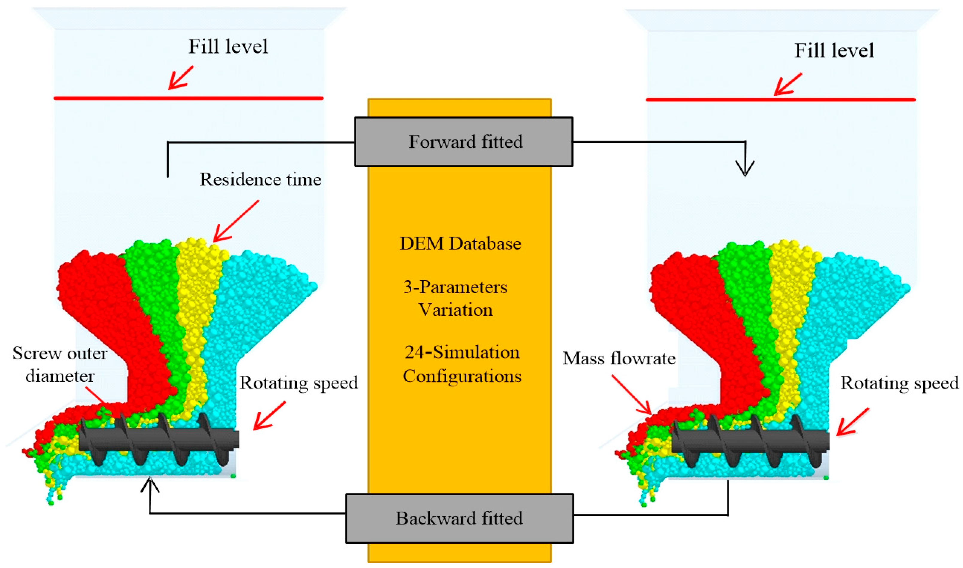
Screw speed is a key parameter, and there is significant variability in conveying capacity under different operating conditions. The screw shaft is connected to the variable speed drive to achieve uniform casting or other operational objectives. The operating conditions for the numerical simulations are designed using the DOE method to determine the parameter combinations. Then, the discharge behavior is simulated by the DEM model of the screw conveyor. This paper proposes a method for estimating concrete workability in process control by mass flow rate and screw speed. In addition, the forward model is fitted according to the operating parameters, i.e., to evaluate the screw conveying capacity. The backward model is used directly in the machine’s control system to overcome the discharge instability caused by the residence time. The forward and backward-fitting relationships based on the numerical simulations are shown in
Figure 1. This research can be used as a theoretical basis for the design of screw control strategies. It can help the equipment to achieve the quantitative and automatic casting function.
2. Screw Conveyor DEM Method
The residence time mainly affects the workability of concrete (flowability and viscosity). This means the longer the time, the lower the moisture level. The changes in the workability of concrete have a direct effect on the speed of particle movement and the drive torque of the screw shaft. In other words, as the viscosity of concrete increases (poor flowability), more energy is required to maintain a constant conveying capacity. In addition, the screw conveying efficiency also decreases. The concrete is considered to be composed of mortar and stone particles, and the detailed physical properties of the materials are described in the literature by Zhang et al. [
25]. The stone particle size is 5–15 mm, the mortar particle size is less than 2 mm. The densities of the stone and mortar particles are 2591 kg/m
3 and 3210 kg/m
3, respectively.
DEM is a numerical simulation of the discharge process, allowing visualization and recording of particle trajectories. The mechanical relationships for particle–particle, and particle–contact wall interactions are calculated. For the DEM method, the main difficulties are the large amount of computation and the long cycle time. Currently, most researchers have reduced the cycle time by scaling the particle size [
2,
8]. To reduce the calculation, the mortar particle size is uniformly set to 5 mm spheres. The Hertz–Mindlin slip-free model is used for stone particles in the numerical simulation, and the Johnson–Kendall–Roberts model is used for mortar particles. In this case, the cohesion coefficient is used to describe the viscosity of concrete in the simulation. To accurately describe the residence time, which affects the workability of concrete, the time function of the cohesion coefficient is fitted using a combination of numerical simulation and experimental methods. More details on the DEM model and the function of the cohesion coefficient are available in previous research [
25,
26]. The results of the physical parameters are shown in
Table 1.
The screw conveyor is an experimental platform in this paper. Its structural and process parameters are shown in
Table 2. With the application of periodic boundary conditions to the screw conveyor, the DEM model is simplified, as shown in
Figure 2. The DEM model of the screw conveyor can accurately describe how the particles move while conveying. The results of the simulation have been demonstrated in previous research, with details given in the literature by Yu et al. [
2,
26].
3. Operating Conditions
The main operating conditions are different combinations of screw outer diameter, residence time, and screw speed, as detailed in
Table 3. This paper focuses on the effect of residence time on conveying performance without considering the load factor, screw pitch, etc. The effect of these factors will be considered in future work. A total of 24 groups are identified using the DOE approach, and details of the experimental design experience and handling can be found in the literature by Cleary et al. [
27]. The ranges of the three influence factors are shown below:
- (1)
The screw’s outer diameter is reduced from 60 mm to 45 mm in 5 mm increments, primarily to accommodate the change in screw volume.
- (2)
The residence time varies from 0 to 30 min in 10 min increments, primarily to account for the residence time affecting the workability of concrete.
- (3)
The screw speed is increased from 15 r/min to 30 r/min in 5 r/min increments, primarily to account for the variation in material handling capacity.
The description of the screw conveying mechanism also uses the same key structure nomenclature as Zhang et al. [
25] and Yu et al. [
26]: The particles are filled with screw shaft cavities called screw fill volume. Particles’ movement is usually determined by the shear force of the screw shaft. When the particles are transported from the first pitch, the starting point is the “root” of the screw. When the particles move to the last pitch, the destination is the “end” of the screw. The mass flow rate is the mass of particles transported by the screw per unit time. The conveying capacity of the screw conveyor provides important information about the operating conditions and can be used to control stable operation. These indicators vary with the different operation conditions. The mathematical model between the indicators and operating parameters can be fitted based on the corresponding results.
4. Discharge Pattern of Concrete
The effect of screw outside diameter, screw speed, and residence time on the motion behavior and mass flow rate is discussed using the DEM model. The initial fill of concrete is 50% of the hopper volume, which is calculated to be 70,600 mortar particles and 8400 stone particles. The numerical simulation time is 20 s in 1 s increments.
Figure 3 shows the ‘snapshot’ of the screw conveying concrete particles under different outer diameters.
Figure 3 shows run 01, run 08, and run 09, respectively. In the simulation, the particle flow is represented by the combination of spherical particles and vector arrows. The direction and length of the arrow indicate the speed of the particle motion. Here, relatively high speed is indicated by a red arrow and lower speed by a blue arrow. The figure provides a visual representation of particle dynamics, spatial distribution, and trajectory. To quantify the discharge mass flow, the mass sensor grid (40 × 40 × 40 mm) is installed at the screw outlet.
Figure 3 (right) shows the time-varying curve of the mass flow rate.
Figure 3 shows that as the screw’s outer diameter increases, the number of filling particles in the screw volume increases. At the same time, the screw conveying capacity increases. It also enhances the disturbance capacity of the screw shear, which slightly increases the motion rate of the particles to fill the volume. The particle velocity vector is positively correlated with the screw’s outer diameter. As the outer diameter increases, the number of red vector arrows for the particles (X and Z directions) also increases. Furthermore, the radial velocity of the particles is accelerated, which increases the sliding capacity. In terms of discharged mass flow, increasing the screw outside diameter results in increased conveying capacity. The increased screw disturbance causes a higher frequency of peak transients in the mass flow versus time curve. There is also a degree of randomness in where the peaks occur. Similarly, it also increases the tangential slip or centrifugal movement of particles. The most effective concrete transport is achieved when the screw’s outer diameter is 60 mm.
Figure 4 shows the movement behavior and mass flow rate of the conveyed concrete particles at screw speeds of 15 r/min and 20 r/min (run 02 and run 03). It can be seen that as the rotational speed increases, the axial and radial velocities of the concrete particles also increase together, especially around the outside of the screw blade. The axial movement of the particles is the main movement, and increasing their speed increases the conveying capacity. The radial speed of movement acts as a resistance and increases the centrifugal movement of the particles in radial deviation. It is the main reason why the mass flow increases with screw speed, but the growth gradient is not ideally linear. In addition, as the screw speed increases, so does the degree of mutual extrusion and collision of particles in the hopper.
The time variation curve of the mass flow is obtained by counting the screw capacity per time, as shown in
Figure 4 (right). It can be seen that the mean mass flow increases significantly as the screw speed increases. At the same time, there is an increasingly large amplitude of change in the values calculated by the conventional theoretical model for both of them [
28]. Therefore, as the screw speed increases, which affects the volumetric efficiency of the screw shaft. The results of the above analyses are fully consistent with the conclusion that screw speed is positively correlated with throughput, but the growth trend is non-linear.
The particle-particle or particle-wall adhesion coefficients as the function of residence time (run 05 and run 06) and the discharge pattern are shown in
Figure 5. It can be seen that the velocity vector of concrete particles decreases as the residence time increases. For the screw volume, the increasing particle viscosity is caused by longer times. Increasing particle viscosity increases the blade resistance to axial shear from moving particles. Also, the particle porosity within a single pitch volume increases, as shown by the black dashed markers in
Figure 5. This causes the discharge mass flow (mean value) to decrease. In contrast, the dispersion of the instantaneous values increases. For particle filling motion, longer time scales result in a decrease in the number of particles moving vertically—a lower filling rate. Overall, it shows a reduced area of particles disturbed by rotating screws.
In order to investigate the effect of the time scale on the mass flow rate, the time variation curves of the mass flow for residence times of 20 min and 30 min are counted, as shown in
Figure 5 (right). From the figure, the time scale is inversely proportional to the mass flow rate. The variation trend is somewhat dispersive, and the degree of dispersion is positively correlated with the time scale, as indicated by the number of red coils in the figure. This is mainly due to increased particle viscosity, resulting in greater porosity within the screw volume and random location. Therefore, the workability of the concrete as a time variable has a significant effect on the mass flow rate in batch production.
5. The Mass Flow Rate by Screw
The mass flow rate is a key indicator for the evaluation of screw conveyors, which has a direct impact on the molding quality of the PC, i.e., the length, width, and thickness dimensions. For this reason, we investigate the change rule of the conveying capacity by calculating the mass flow under different operating conditions.
Figure 6,
Figure 7 and
Figure 8 show the mass flow rate for the individual variables: screw out diameter, rotational speed, and residence time.
As shown in the figure, when the screw’s outer diameter is increased from 45 mm to 60 mm (screw speed 30 r/min), the mean error between the simulated and experimental values of mass flow is only 6.3%. Similarly, when the screw speed is increased from 15 r/min to 30 r/min (screw’s outer diameter 60 mm), the mean error of mass flow is 8.95%. When the residence time is increased from 0 min to 30 min (screw’s outer diameter 60 mm, speed 30 r/min), the mean error of mass flow is 2.7%. Research shows that the DEM model of the screw conveyor can accurately describe the discharge behavior in batch production.
The results of the conveying capacity as a function of the three input parameters are as follows:
The mass flow increases within a certain range as the screw speed increases. When the speed exceeds a critical value, the mass flow is stabilized.
As the residence time increases, the mass flow decreases. These observations are directly related to the stacking height of the particles in the hopper and the vectorial velocity of the axial movement.
At constant screw speed, the mass flow rate increases as the screw’s outer diameter increases.
The sensitivity ranks of the influencing factors are derived from the gradient of mass flow change: rotational speed, residence time, and the screw’s outer diameter.
For constant material properties, increasing screw speed and outside diameter can increase conveying capacity. Similarly, for the same screw speed, the mass flow rate is inversely proportional to the time scale in batch production (with longer times leading to increased particle adhesion). There is also a more significant effect on the degree of dispersion. However, over the range of screw outer diameters, it has a relatively small effect on mass flow. Above a critical value, the effect becomes more significant.
6. Correlation between Operating Conditions and Conveying Capacity
The relevant coefficients have been calculated to determine the relationship between the operating variables and the mass flow. In the backward-fitting model, the sensitivity of the time scale affecting the mass flow rate is significant. The absolute value of the relevant coefficient is −0.93. The effect of screw speed is also more sensitive to mass flow. The relevant coefficient is 0.98. The sensitivity of the screw outer diameter to the effect of mass flow is relatively low, with a relevant coefficient of 0.28. This shows that the mass flow rate is negatively correlated with the screw’s outer diameter. However, the magnitude of the change is relatively small.
In the forward-fitting model, the increase in particle viscosity can be seen as the mass flow rate decreases at constant speed. This also means that the production cycle affects the physical properties of the material. Additionally, the increased resistance to the interaction of particles with the blade. It is possible to modify key parameters in the control system to ensure stable and accurate casting based on the forward and backward-fitted models.
7. Fitted Model Relating Conveying Capacity and Operating Conditions
We carried out the multiple regression analysis based on the data listed in
Table 3. The analysis was used to determine a predictive model for estimating performance indicators.
In the forward-fitting direction (as shown in
Figure 1), screw speed, residence time, and the screw’s outer diameter are functions of the conveying capacity.
In the backward-fitting direction, the conveying capacity is a function of the operating variables. In these analyses, the screw speed is considered as a known quantity under all operating conditions. It is included as an independent variable in both the forward and backward-fitting models.
7.1. Forward Model for Estimation Residence Time
Regression analysis is used to determine the relationship between the interaction between operating parameters and conveying capacity.
The optimal predictive regression model for the effect of residence time on concrete workability is as follows:
We use a second-order model to forecast residence time as shown in
Figure 9. Here, the solid red line shows that the predicted value is equal to the actual value. According to Equation (1), the residence time can be predicted based on the mass flow rate and speed. Concrete workability is calculated from the residence time during the batch production process. Slump and extensibility are used as indices to assess workability [
2]. Those have been determined experimentally, and the prediction model obtained is shown in Equations (2) and (3) [
26].
7.2. Backward Model for Estimation of the Mass Flow Rate
Inverse regression analyses determined the relationship between operating parameters and conveying capacity. The optimal model for the prediction of the effect of multiple factors on mass flow rate is
We use a first-order model to forecast the mass flow rate as shown in
Figure 10. According to Equation (4), the conveying capacity can be forecasted based on the residence time, speed, and outer diameter.
8. Creating Operating Strategies to Account for Batch Production
In the batch production process, the material properties are influenced by the residence time in the machine. The process exhibits typical time-varying characteristics. The purpose of this section is not to explain how to optimize the design of the screw structure to suppress material property changes but rather to explore how to adjust the screw speed to maintain the steady-state casting. By proposing a reasonable parameter adjustment strategy, the particle flow management plan is formulated to achieve constant initial conveying capacity. The relationship between residence time and mass flow is discussed. Examples are given for the 60 mm and 50 mm outer diameter sizes. The screw speed compensation value is calculated, and the result is shown in
Figure 11.
As shown in the figure, there are similar trends in speed compensation to maintain a constant conveying capacity at different residence times. The difference is mainly in the gradient of change. Based on the experimental platform for conveyor speed compensation experiments, the results show that the errors between regression model predicted values and experimental values are reasonable.
With increasing residence time, particle-particle and particle-blade cohesion improves, leading to lower downward filling rates and axial movement. By fitting a multivariate equation containing the time scale to the screw speed compensation, the stability conveying function of the machine can be achieved. It is worth noting that the sensitivity of the speed compensation to residence time is significant within 20 min and increases almost linearly. However, the growth gradient of speed compensation begins to slow down in the range of 20 min to 30 min. The concrete workability is affected by the time scale, indicating the existence of a critical value. When the residence time exceeds 20 min, the viscosity and flowability of the particles usually change very little. However, the filling ratio and axial flow are relatively stable. The effect of time scale on throughput cannot be ignored. Adjusting the screw speed is an important operational strategy to control the stability of continuous discharge. This is also the research direction for abnormal conveying due to screw shaft wear. Next, the wear mechanism of the screw shaft is studied using the DEM-FEM method. At the same time, the change rule of concrete conveying capacity in the process of screw shaft wear is further investigated.
9. Conclusions
The numerical model of the concrete is constructed using the DEM method. The mechanism of screw conveying concrete is simulated and analyzed under different operating conditions. A total of 24 combinations of operating parameters have been designed using DOE design methods. The visualization analyzes the axial and radial velocity vectors of the concrete particles in the screw conveyor. It also quantified the variation pattern of the discharge throughput. The simulation analysis of the casting behavior led to the following specific conclusions:
The conveying capacity is positively correlated with the screw’s outer diameter for constant concrete workability and screw speed. Increasing the screw’s outer diameter results in more axial movement particles and faster velocity vectors. In addition, the enhanced radial segregation sliding ability of the particles under shear thrust increases the instantaneous variance of the mass flow rate, especially for larger particle diameters.
The mass flow is negatively correlated with residence time at constant screw speed and outside diameter. As the residence time increases, particle cohesion increases. This leads to a synchronous decrease in the axial and radial velocity vectors. This also reduces the instantaneous variance of the mass flow. The sensitivity order of the influencing factors was derived: rotational speed, residence time, and the screw’s outer diameter.
Forward regression analysis provides the mathematical model for accurately predicting conveying capacity as the function of rotational speed, residence time, and the screw’s outer diameter. The correlation coefficient of these fitted models is 0.98, indicating a more reliable predictive accuracy. It is possible to predict the state of the discharge performance indicators in the process production.
Inverse regression analysis provides a predictive model for concrete workability as the function of rotational speed and mass flow rate. The error between the predicted speed compensation value and the experimental value is within a reasonable range, indicating a more reliable predictive accuracy. It is possible to evaluate concrete properties based on screw speed and mass flow rate. This model is suitable for the weight control of the screw conveyors and allows the design of the operating strategies. For example, increase the screw speed to compensate for residence time effects and maintain stable discharge.


