Abstract
Active and passive vibration control systems are of paramount importance in many engineering applications. If an external load excites a structure’s resonance and the damping is too low, detrimental events, such as crack initiation, growth and, in the worst case, fatigue failure, can be entailed. Damping systems can be commonly found in applications such as industrial machines, vehicles, buildings, turbomachinery blades, and so forth. Active control systems usually achieve higher damping effectiveness than passive ones, but they need a sensor to detect the working conditions that require damping system activation. Recently, the development of such systems in rotating structures has received considerable interest among designers. As a result, the development of vibration monitoring equipment in rotating structures is also a topic of particular interest. In this respect, a reliable, inexpensive and wireless monitoring system is of utmost importance. Typically, optical systems are used to measure vibrations, but they are expensive and require rather complex processing algorithms. In this paper, a wireless system based on a commercial MEMS accelerometer is developed for rotating blade vibration monitoring. The proposed system measurement accuracy was assessed by means of comparison with a reference wired measurement setup based on a mini integrated circuit piezoelectric (ICP) accelerometer adapted for data acquisition in a rotating frame. Both the accelerometers were mounted on the tip of the blade and, in order to test the structure under different conditions, the first four blade resonances were excited by means of piezoelectric actuators, embedded in a novel experimental setup. The frequency and amplitude of acceleration, simultaneously measured by the reference and MEMS sensors, were compared with each other in order to investigate the viability and accuracy of the proposed wireless monitoring system. The rotor angular speed was varied from 0 to 300 rpm, and the data acquisitions were repeated six times for each considered condition. The outcomes reveal that the wireless measurement system may be successfully used for vibration monitoring in rotating blades.
1. Introduction
A key problem in many engineering applications is the control of vibrations, because if the damping is too low, they lead to noise and loss of performance. Moreover, if the dynamic load which causes vibrations exceeds the fatigue limit, the safety operation of the structure is undermined [1]. Vibration damping and control systems are commonly found in industrial machines, vehicles, buildings, turbomachinery blades, and so forth. In particular, turbomachinery is extensively deployed for electric power generation, nautical and aeronautical propulsion, and wind turbines for renewable energy extraction; however, the pursuit of the most successful methods for vibration control in turbine blades is still under extensive investigation. In this context, passive vibration damping systems, such as friction dampers and shrouded blades, are still the most popular [2,3]. Nevertheless, several resonance conditions may be involved throughout the engine’s operations, and the possibility of adapting the damping effectiveness to each critical condition is ensured by active damping systems. Several efforts are still being made to implement such systems [4,5]. In this regard, the advent of smart materials, such as piezoelectrics, has provided designers with new solutions. Several studies have focused on the implementation of active piezoelectric damping and control in beams and blades, both in fixed and rotating frameworks [6,7,8,9,10,11,12,13]. For example, in Refs. [5,14], it was demonstrated that an active damping system based on PZT actuator arrays can always operate at its maximum effectiveness if the voltage electrically is optimized according to the excited mode. However, the proposed active controls require vibration detection systems to be effectively implemented, and both the accuracy of the measurement device exploited to detect the excited eigenmodes and the corresponding vibration amplitude play a key role. In this regard, the development of online vibration monitoring equipments in rotating structures is a topic of particular interest. Nowadays, there is an increasing demand for remotely controllable devices, and thanks to the Internet of Things (IoT) paradigm, it is possible to extend Internet connectivity to common objects. The availability of billions of connected devices scattered around the world, each capable of acquiring and analysing data, opens up new possibilities for the development of new data gathering systems and the development of methods for the automatic management of such large data sets, enabling new digital services [15]. In Refs. [16,17] the IoT for vibration monitoring and fault diagnostics of rotating machinery was analyzed by using vibration analysis, and seemed very promising. Traditional vibration monitoring techniques involve the deployment of accelerometers to detect the modal characteristics of the blade, that is, eigenfrequencies, mode shapes, and so forth [18,19,20]. Recently, contact vibration monitoring systems, such as strain gauges, were investigated; however, due to their complex implementation, limited operating life, and low reliability, their practical application remains unfeasible [21,22,23,24]. A wireless vibration monitoring system based on acceleration measures in an operating wind turbine was proposed in Ref. [25], while in Ref. [26] a wireless inertial measurement unit capable of sensing angular speed and tri-axial accelerations was experimentally investigated on a 3 MW wind turbine. Lately, a contactless measurement method denoted as the blade tip timing (BTT) has been proposed. The BTT detects the deflection of the blade tip by means of optical probes located in the machine case [27,28]. However, the probes’ placement around the casing internal surface is non-trivial, since the surface is also filled with structural elements and nozzles. Moreover, the number of deployable optical probes is usually limited, thereby the vibration data acquired with the BTT method showed non-uniform and sub-Nyquist sampling [29]. For these reasons, the identification of the vibrations of the blades involves highly demanding data processing software, but the hardware cannot always comply with the requirements of the processing algorithms [30]. Currently, this technology still remains immature for its practical implementation in gas turbines. Other recent studies reported new contactless vibration measurement systems based on laser scanning and ground-based radars [31,32,33], but they can only be used for detecting large vibration amplitudes in operating blades. The recent development of MEMS-based fabrication techniques has provided an alternative for designers owing to their cost-effective and lightweight features that make them particularly attractive for the vibration monitoring in rotating structures. Notably, analog or digital signals of MEMS accelerometers can be easily acquired, even with inexpensive microcontrollers. This represents the major advantage over traditional ICP accelerometers which are more accurate and reliable, but would require wired data transmission, such as slip rings or expensive and bulky integrated charge amplifiers and wireless data transmission modules. In the last decade, several studies have been performed on the on-rotor acceleration measurement by means of MEMS accelerometers [34]. Arebi et al. [35] deployed a MEMS accelerometer on a rotating shaft to measure the shaft misalignments and compared the results with those measured by an optical encoder, and an excellent agreement was found. A lightweight MEMS accelerometer was successfully exploited by Ref. [36] for studying a shaft’s critical speeds during the start-up of a machine and the instantaneous torque measurement in induction motors [37]. Thompson [38] explored the viability of using a high-range (9810 m/s) and low-sensitivity MEMS accelerometer to measure the centrifugal acceleration on a five-blades rotor fan disk. The outcomes demonstrated the potential for MEMS accelerometers implementation in fan and compressor rotor blades for structural health monitoring and vibration monitoring. A spectrum analyser using the Raspberry Pi and a tri-axial digital MEMS accelerometer for vibration monitoring in rotating machinery was also developed by Ref. [39]. A disadvantage of employing digital output MEMS accelerometers lies in the evaluation of the amplitude and phase of vibration, since a frequency shift in the sample clock affects the accuracy of the sensor [40]; although, a theoretical model was proposed by Cheung [41] to resample the acceleration data and compensate the frequency shift error. However, the recent optimization and refinement of MEMS-based manufacturing technologies allowed to improve the performance of such sensors without significantly increasing their fabrication cost [42]. This paper explores the possibility of using a commercial MEMS to monitor vibration. A wireless system is developed for real-time rotating blades vibration monitoring by exploiting a commercial MEMS analog accelerometer. Its characterization was carried out by comparing the simultaneously acquired data with a more accurate and reliable reference system, based on an ICP accelerometer, that has been adapted to operate on rotating structures. Both the accelerometers were mounted on the tip of the blade, and the first four blade resonances were excited by means of piezoelectric actuators with the aim of replicating the most severe loading conditions. The frequency and amplitude of acceleration, simultaneously measured with both reference and wireless systems, were compared with each other in order to investigate the viability and accuracy of the proposed system. The data acquisitions were repeated six times for each considered resonance, and the measurement error was estimated by calculating the Mean Absolute Percentage Error (MAPE). It has been seen that this is always less than 5%, indicating a fair accuracy of the proposed wireless setup. The influence of angular velocity was also studied by repeating all the measurements with angular velocities between 0 and 300 rpm. The wireless system power consumption was always lower than 6 W during the whole measurement campaign. An active vibration damping system in rotating blades might benefit from the proposed wireless system, since it would allow not only for the real-time and remote monitoring of vibration, but also optimize the effectiveness of the damping system according to the resonance excited by the external load. The paper is organized as follows: the wireless vibration monitoring system and the measurement setup of the reference accelerometer are described in Section 2 alongside the adopted measurement procedure. Experimental results are provided and discussed in Section 3.
2. Materials and Methods
An actual fan blade from the second fan stage of the Pratt&Whitney JT8D-9 turbofan engine was used as a rotor for the experimental tests. Fourteen customized lead zirconate titanate (PZT) flexible actuators, based on PIC 255 material, were evenly distributed in seven pairs along the pressure surface (PS) of the blade, as depicted in Figure 1. The materials and geometric specifications of both the blade and PZT actuators are listed in Table 1.
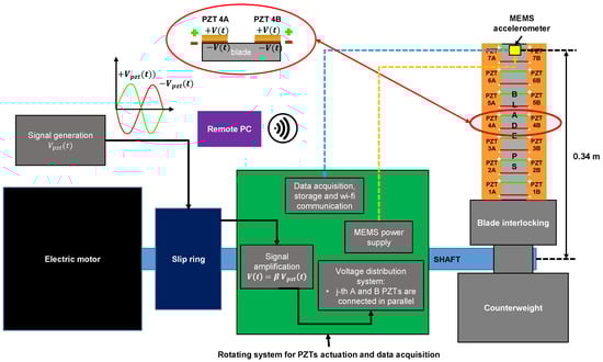
Figure 1.
Functional scheme of the wireless vibration monitoring system. The shaft rotating speed is set with an inverter that drives the electric motor. The PZT’s driving voltage is generated by a waveform generator and, by means of a slip ring, is amplified within the rotating system for PZT actuation and data acquisition. The amplification stage provides both and , which are distributed on each PZT actuator’s pair in order to excite the resonance of the blade. The MEMS accelerometer data were acquired with an on-board data acquisition and storage system that sends data to a remote PC via wi-fi communication. The MEMS accelerometer is battery-powered at 3.6 V.

Table 1.
Material and dimensions of the blade and PZT actuators.
2.1. Wireless Vibration Monitoring System
The wireless system for vibration monitoring consists of four main sub-systems (Figure 1):
- Electric motor: the electric motor is driven by an inverter to adjust the blade angular speed.
- Fan blade coupled with seven pairs of PZTs, shaft and interlocking system: the fan blade is covered with 14 PZT actuators evenly distributed along the pressure side of the blade. An ad hoc interlocking was realized to couple the shaft with the blade. A counterweight was fixed to the interlocking to balance the weight of the blade.
- Rotating system for electric voltage amplification and distribution: the waveform generator Yokogawa FG420 provides with V and kHz. The PZT’s driving signal from the waveform generator was magnified by in-house developed amplifiers, which are located within the rotating system for PZT actuation, by means of a slip ring (SENRING SNG025-06S). The amplifiers were supplied with batteries and DC–DC boost converters, that allows to obtain up to 300V peak-to-peak. One amplifier is set in inverting configuration, whereas the other is in non-inverting configuration. Thereby, two actual driving voltages and can be used to drive the PZT actuators [43]:with being the gain of the amplifiers. The PZT’s driving voltage distribution was accomplished via mechanical relays handled by Arduino Uno. Each relay was electrically coupled to a pair of actuators which occupy the same radial gap on the blade’s surface.
- Wi-fi data acquisition system.This system is connected directly to the rotating shaft (on board). A battery-powered real-time data monitoring and acquisition system was developed to measure the acceleration exerted by PZT actuators. A MEMS accelerometer (ADXL356) was glued on the PS blade’s tip, and its signal was acquired by means of a commercial DAQ hat (MCC118). The DAQ is capable of acquiring analog signals (±10 V) with 12-bit resolution, up to 100 kS/s, and it is powered and handled by a Raspberry PI 4. A remote PC was used to control the Raspberry PI 4 and visualize the accelerometer signal in real time, exploiting wi-fi communication.
2.2. Reference Vibration Monitoring System
The acceleration measurement system taken as a reference consists of (Figure 2):
- An ICP PCB 352A56 accelerometer glued at the tip of the blade suction surface (SS) in order to measure the same acceleration of the MEMS accelerometer;
- A PCB 482C signal conditioner that is wired to the PCB accelerometer using the slip ring;
- A data acquisition board National Instruments NI USB-6341 for the reference accelerometer data acquisition by means of an ad hoc developed LabView routine. The accelerometer data were delivered to the DAQ by means of the SENRING SNG025-06S slip ring.
The main specifications of both the vibration measurement systems are listed in Table 2.
Table 2.
Main specifications of both the acceleration measurement systems.

Figure 2.
Functional scheme of the reference vibration monitoring system. The reference accelerometer mounted on the blade tip suction surface (SS) is powered by a signal conditioner via the slip ring wires. The signal conditioner is wired to the data acquisition board that is controlled by a remote PC by means of a LabView routine.

2.3. Measurement Test Protocol
In order to test the most structurally severe operating conditions, the measurements were performed simultaneously with both the acceleration systems, while exciting the first four eigenfrequencies of the blade and selecting different rotor angular speeds. The four natural frequencies correspond to 80 Hz, 302 Hz, 818 Hz and 1220 Hz, and they were used to generate the corresponding harmonic voltage , as reported in Section 2.1. Experimental trials were carried out for the following conditions: 0 rpm (static), 120 rpm, 180 rpm, 240 rpm, and 300 rpm. Before carrying out the acceleration measurements by inducing the resonance of the blade via PZT actuators, noise baseline measurements (with de-activated PZT actuators) were carried out for every considered condition. In this way, the sensor’s noise, due to any electromagnetic interferences and vibrations caused by the rotating framework imbalances, was recorded. The measurement range of ±98.1 m/s was chosen for the MEMS accelerometer in order to exploit the sensor’s highest sensitivity (Table 2). The overall measurement campaign consists of 20 test conditions, and each one was repeated a minimum of six times. The trials were randomized in order to make the experimental and control groups probabilistically equal with respect to all potential confounding variables, and thus minimizing the bias due to the initial differences between the treatment conditions. The data acquisitions were performed simultaneously for both the measurement systems. A sampling rate of 16 k sample/s was set for both the DAQs and each trial was acquired for 4 s. The data were subsequently processed with an in-house routine developed in the MATLAB environment. In particular, a fast Fourier’s transform (FFT) of all the signals was performed to analyze the accelerations in the frequency domain. The spectral components of the baseline noise detected by the two accelerometers in each test condition were filtered. Thereby, the acceleration amplitudes of both the accelerometers were evaluated, and the MAPE was calculated between the reference accelerometer (considered as the actual value) and the MEMS accelerometer in order to estimate the proposed wireless vibration monitoring system accuracy. The MAPE was evaluated as follows:
with n, and being, respectively, the number of trials and the acceleration measurement obtained, respectively, with the reference and MEMS-based system.
3. Results and Discussion
In this section, the results obtained with both the vibration monitoring systems are presented with the corresponding uncertainties expressed as standard deviations. Figure 3 illustrates the raw data of two signals acquired with the reference and MEMS accelerometers in two different test configurations. It can be seen that the data acquisitions were simultaneously performed. In particular, the first 10 oscillation periods are plotted for both cases: Figure 3a,b show, respectively, the acceleration measured in the case of the first resonant mode at a rotor angular speed of 180 rpm and the acceleration obtained by exciting the blade at the second eigenmode for a rotor speed of 300 rpm.
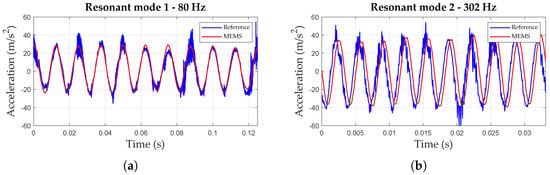
Figure 3.
Plots of accelerations measured over time in the case of: (a) the first resonant mode at a rotor speed of 180 rpm and (b) the second resonant mode at 300 rpm.
It can be seen that the signal acquired by the wireless system appears much smoother than the reference one. This is mainly due to the slip ring used to bring back the reference accelerometer signal that might introduce noise, and the 2.4 kHz bandwidth of the MEMS accelerometer. Figure 4 and Figure 5 show the spectra calculated from the reference and MEMS accelerometers at two rotor angular speeds, namely 180 and 300 rpm, and by exciting the first four blade-bending eigenmodes via PZT actuators. The spectral components of the baseline noise were assessed in tests performed with de-activated PZT actuators at each considered rotor speed and removed from the depicted spectra. The FFTs were plotted within a 0–1500 Hz frequency range in order to appreciate the components of all the four resonant modes with the same frequency scale. From a closer inspection of the Figure 4 and Figure 5, it can be seen that the frequency component corresponding to the highest acceleration amplitude always corresponds to the excited eigenmode, considering a standard uncertainty of Hz due to the frequency resolution given by the time window for acquisition (4 s).
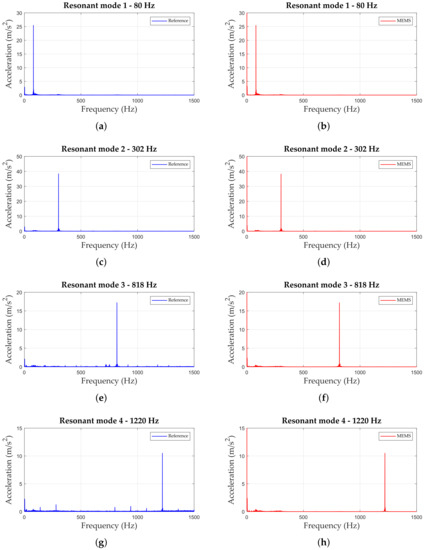
Figure 4.
FFT of the reference and MEMS accelerometer signals at a rotor speed of 180 rpm considering: (a,b) the first resonant mode, (c,d) the second resonant mode, (e,f) the third resonant mode, and (g,h) the fourth resonant mode.
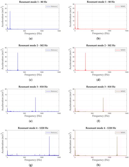
Figure 5.
FFT of the reference and MEMS accelerometer signals at a rotor speed of 300 rpm, considering: (a,b) the first resonant mode, (c,d) the second resonant mode, (e,f) the third resonant mode, and (g,h) the fourth resonant mode.
The peak values, expressed in m/s, were then compared to evaluate the accuracy of the wireless vibration monitoring system. Table 3 summarizes the results obtained for all the considered rotor angular velocities and resonant modes. The proposed wireless system always showed an overall maximum error less than 5%, while the maximum difference between the average acceleration values measured by means of both systems was 0.39 m/s in the case of the third resonant mode at an angular speed of 240 rpm. Figure 6 reports the results expressed in terms of mean and standard deviation, obtained by comparing the FFT peaks derived from each accelerometer and evaluating the MAPE. It appears that the MAPE grows with the rotor angular speed; this behaviour could be due to the increasing centrifugal acceleration, which affects the MEMS accelerometer accuracy.
Table 3.
Mean acceleration amplitude ± standard deviation calculated from both the acceleration measurement systems (Reference and MEMS-based system).
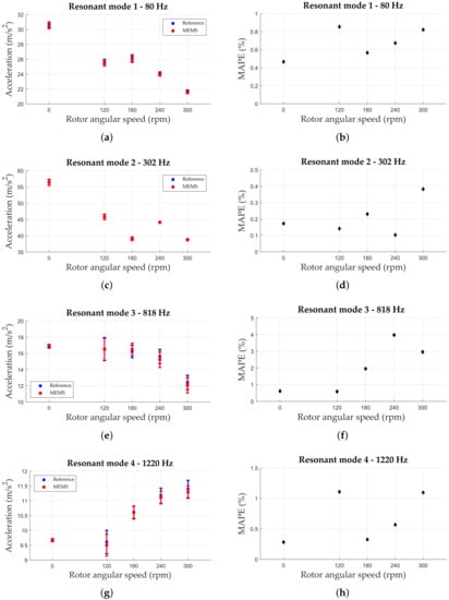
Figure 6.
Comparison between wireless and reference acceleration measurement systems within the considered rotor angular speeds. Mean acceleration amplitudes are reported alongside their corresponding error bars representing the standard deviation for: (a) the excitation of the first bending mode, (c) the excitation of the second mode, (e) the excitation of the third mode, and (g) excitation of the fourth mode. (b,d,f,h) show, respectively, the values of the mean absolute percentage errors (MAPE) for the first four bending modes excitation within the considered rotor speed range.
Figure 6 also shows the results obtained by comparing the peaks of the spectra which have been used for the evaluation of the MAPE (Equation (2)). It is worth noting that, for all the test configurations, both the acceleration amplitude and the corresponding frequency evaluated through the MEMS-based wireless system are compatible with the ones assessed with the reference monitoring system. According to the presented outcomes, the proposed inexpensive vibration monitoring system may be deployed both in wind turbine and turbomachinery fan blades by positioning the accelerometer at a proper distance from the rotation axis. The power consumption of both the reference and MEMS-based wireless systems is another critical feature that should be compared. In fact, while the reference system includes benchtop instruments that require hundreds of watts, without considering the remote PC power consumption, the wireless system must be able to operate in a rotating framework, thereby a low power consumption is entailed. Table 4 summarizes the key characteristics of both setups in terms of power supply requirements. The wireless system power consumption was always lower than 6 W during the whole measurement campaign. This power demand can easily be met from small-size solar panels, as reported in Ref. [44], eliminating the need for a slip ring to supply the proposed device.
Table 4.
Main power supply requirements for each considered vibration monitoring system.
The proposed vibration monitoring system appears to be capable of accurately detecting vibrations at a resonance within 2.4 kHz. This bandwidth is much wider than 1–150 Hz, which would be required to monitor the first nine resonances in axial wind turbine blades longer than 2.5 m [45]. Moreover, the MEMS-based system offers the remarkable advantage of real-time and remotely controllable monitoring. This is critical for the viability of the proposed device, since it is essential to accurately assess both frequencies and accelerations to evaluate whether the rotating structure is safely operating or the vibration level exceeds the warning threshold and activate, if present, an active control system.
4. Conclusions
An inexpensive wireless vibration monitoring system based on Raspberry PI and a MEMS accelerometer has been proposed, and its accuracy in acceleration measurements was evaluated by means of comparison with a reference measurement system. An actual fan blade from a gas turbine engine was used as a rotating framework, and its eigenmodes were excited by means of an in-house prototype for PZT actuator control. The blade was rigidly coupled to a rotating shaft and the first four bending modes of the blade were excited by means of the PZT actuators to experimentally replicate its resonance conditions. The accelerations detected by both vibration monitoring systems were processed and compared to estimate the accuracy of the proposed wireless system under several rotor angular speeds (0, 120, 180, 240 and 300 rpm). The MEMS-based system showed fair accuracy for both frequency and acceleration amplitude evaluation with respect to the reference system. The mean absolute percentage error (MAPE) was always less than 5%, indicating the fair accuracy of the proposed wireless setup. Furthermore, the wireless system power consumption was always lower than 6 W during the whole measurement campaign. Such power demand can easily be provided from small-size solar panels. This suggests that the proposed wireless system may be exploited for wind turbine and turbomachinery fan compressor blade vibration monitoring.
Author Contributions
Conceptualization, A.R., G.B. and F.B.; methodology, A.R., G.B., F.B. and A.S.; validation, A.R., G.B. and F.B.; investigation, A.R. and G.B.; data curation, A.R. and G.B.; writing—original draft preparation, A.R., G.B., F.B. and A.S.; writing—review and editing, A.R., G.B., F.B. and A.S.; visualization, A.R. and G.B.; supervision, F.B. and A.S. All authors have read and agreed to the published version of the manuscript.
Funding
This research received no external funding.
Institutional Review Board Statement
Not applicable.
Informed Consent Statement
Not applicable.
Data Availability Statement
Not applicable.
Conflicts of Interest
The authors declare no conflict of interest.
References
- Poursaeidi, E.; Bakhtiari, H. Fatigue crack growth simulation in a first stage of compressor blade. Eng. Fail. Anal. 2014, 45, 314–325. [Google Scholar] [CrossRef]
- Roberts, W.B. A Design Point Correlation for Losses due to Part-Span Dampers on Transonic Rotors. J. Eng. Power 1979, 101, 415–421. [Google Scholar] [CrossRef]
- Wadia, A.R.; Szucs, P.N. Inner Workings of Shrouded and Un-Shrouded Transonic Fan Blades. J. Turbomach. 2008, 130, 031010. [Google Scholar] [CrossRef]
- Choi, B.; Kauffman, J.; Duffy, K.; Provenza, A.; Morrison, C. Active vibration reduction of titanium alloy fan blades (FAN1) using piezoelectric materials. In Proceedings of the 2010 Propulsion-Safety and Affordable Readiness (P-SAR) Conference, Jacksonville, FL, USA, 16–18 March 2010. NASA/TM-2010-216335. [Google Scholar]
- Rossi, A.; Botta, F.; Giovannelli, A.; Belfiore, N.P. High efficiency active damping on a fan rotor blade in case of resonant vibrations by means of piezoelectric actuators. In Proceedings of the ASME Turbo Expo 2021: Turbomachinery Technical Conference and Exposition, GT 2021, Virtual, 7–11 June 2021; Volume 9A-2021. [Google Scholar] [CrossRef]
- Botta, F.; Rossi, A.; Schinaia, L.; Scorza, A.; Orsini, F.; Sciuto, S.; Belfiore, N. Experimental validation on optimal placement of pzt plates for active beam multimode vibrations reduction. In Proceedings of the AIMETA 2017—23rd Conference of the Italian Association of Theoretical and Applied Mechanics, Salerno, Italy, 4–7 September 2017; Volume 3, pp. 2258–2269. [Google Scholar]
- Duffy, K.; Provenza, A.; Trudell, J.; Min, J. Passively shunted piezoelectric damping of centrifugally loaded plates. In Proceedings of the 50th AIAA/ASME/ASCE/AHS/ASC Structures, Structural Dynamics, and Materials Conference 17th AIAA/ASME/AHS Adaptive Structures Conference 11th AIAA No, Palm Springs, CA, USA, 4–7 May 2009; p. 2524. [Google Scholar]
- Rossi, A.; Botta, F.; Maiozzi, R.; Scorza, A.; Sciuto, S.A. Experimental results for active control of multimodal vibrations by optimally placed piezoelectric actuators. In Proceedings of the 14th International Conference on Vibration Engineering and Technology of Machinery, VETOMAC 2018, Lisbon, Portugal, 10–13 September 2018; Volume 211, p. 20001. [Google Scholar]
- Goltz, I.; Böhmer, H.; Nollau, R.; Belz, J.; Grüber, B.; Seume, J. Piezo-Electric Actuation of Rotor Blades in an Axial Compressor. In Proceedings of the ETC 2009—8th European Conference on Turbomachinery, Graz, Austria, 23–27 March 2009. [Google Scholar]
- Botta, F.; Rossi, A.; Belfiore, N.P. A novel method to fully suppress single and bi-modal excitations due to the support vibration by means of piezoelectric actuators. J. Sound Vib. 2021, 510, 116260. [Google Scholar] [CrossRef]
- Botta, F.; Toccaceli, F. Piezoelectric Plates Distribution for Active Control of Torsional Vibrations. Actuators 2018, 7, 23. [Google Scholar] [CrossRef]
- Lee, S.L. Active vibration suppression of wind turbine blades integrated with piezoelectric sensors. Sci. Eng. Compos. Mater. 2021, 28, 402–414. [Google Scholar] [CrossRef]
- Kashfi, M.; Fakhri, P.; Amini, B.; Yavari, N. Vibration Analysis of A Wind Turbine Blade Integrated by A Piezoelectric layer. In Proceedings of the The 34th International Power System Conference (PSC2019), Tehran, Iran, 9–11 December 2019. [Google Scholar] [CrossRef]
- Rossi, A.; Botta, F.; Giovannelli, A.; Belfiore, N.P. A novel approach to reduce fan rotor blades stress in case of resonance due to inlet flow distortion by means of piezoelectric actuators. J. Sound Vib. 2023, 548, 117552. [Google Scholar] [CrossRef]
- Lamonaca, F.; Sciammarella, P.; Scuro, C.; Carnì, D.; Olivito, R. Internet of Things for Structural Health Monitoring. In Proceedings of the 2018 Workshop on Metrology for Industry 4.0 and IoT, Brescia, Italy, 16–18 April 2018; pp. 95–100. [Google Scholar] [CrossRef]
- Zhang, X.; Rane, K.P.; Kakaravada, I.; Shabaz, M. Research on vibration monitoring and fault diagnosis of rotating machinery based on internet of things technology. Nonlinear Eng. 2021, 10, 245–254. [Google Scholar] [CrossRef]
- Khademi, A.; Raji, F.; Sadeghi, M. IoT Enabled Vibration Monitoring Toward Smart Maintenance. In Proceedings of the 2019 3rd International Conference on Internet of Things and Applications (IoT), Isfahan, Iran, 17–18 April 2019; pp. 1–6. [Google Scholar] [CrossRef]
- Doliński, Ł.; Krawczuk, M.; Żak, A. Detection of Delamination in Laminate Wind Turbine Blades Using One-Dimensional Wavelet Analysis of Modal Responses. Shock Vib. 2018, 2018, 4507879. [Google Scholar] [CrossRef]
- Pacheco, J.; Oliveira, G.; Magalhães, F.; Cunha, Á.; Caetano, E. Wind Turbine vibration based SHM system: Influence of the sensors layout and noise. Energies 2017, 199, 2160–2165. [Google Scholar] [CrossRef]
- Oliveira, G.; Magalhães, F.; Cunha, Á.; Caetano, E. Vibration-based damage detection in a wind turbine using 1 year of data. Struct. Control Health Monit. 2018, 25, e2238. [Google Scholar] [CrossRef]
- Duan, F.; Zhang, J.; Jiang, J.; Guo, H.; Ye, D. Method to improve the blade tip-timing accuracy of fiber bundle sensor under varying tip clearance. Opt. Eng. 2016, 55, 014106. [Google Scholar] [CrossRef]
- Bornassi, S.; Berruti, T.M.; Firrone, C.M.; Battiato, G. Vibration parameters identification of turbomachinery rotor blades under transient condition using Blade Tip-Timing measurements. Measurement 2021, 183, 109861. [Google Scholar] [CrossRef]
- Zhang, J.W.; Zhang, L.B.; Duan, L.X. A Blade Defect Diagnosis Method by Fusing Blade Tip Timing and Tip Clearance Information. Sensors 2018, 18, 2166. [Google Scholar] [CrossRef] [PubMed]
- Sun, S.; Wang, T.; Chu, F. In-situ condition monitoring of wind turbine blades: A critical and systematic review of techniques, challenges, and futures. Renew. Sustain. Energy Rev. 2022, 160, 112326. [Google Scholar] [CrossRef]
- Loss, T.; Bergmann, A. Vibration-Based Fingerprint Algorithm for Structural Health Monitoring of Wind Turbine Blades. Appl. Sci. 2019, 11, 4294. [Google Scholar] [CrossRef]
- Berkemeyer, F.; Lang, W. Wireless Inertial Measurements on Wind Turbine Rotor Blades. IEEE Sens. J. 2021, 21, 27938–27946. [Google Scholar] [CrossRef]
- Toit, R.G.D.; Diamond, D.H.; Heyns, P.S. A stochastic hybrid blade tip timing approach for the identification and classification of turbomachine blade damage. Mech. Syst. Signal Process. 2019, 121, 389–411. [Google Scholar] [CrossRef]
- Diamond, D.H.; Heyns, P.S.; Oberholster, A.J. Improved Blade Tip Timing measurements during transient conditions using a State Space Model. Mech. Syst. Signal Process. 2019, 122, 555–579. [Google Scholar] [CrossRef]
- Bouchain, A.; Picheral, J.; Lahalle, E.; Chardon, G.; Vercoutter, A.; Talon, A. Blade vibration study by spectral analysis of tip-timing signals with OMP algorithm. Mech. Syst. Signal Process. 2019, 130, 108–121. [Google Scholar] [CrossRef]
- Li, H.; Tian, S.; Yang, Z. A Novel Blade Vibration Monitoring Experimental System Based on Blade Tip Sensing. Materials 2022, 15, 6987. [Google Scholar] [CrossRef] [PubMed]
- Dilek, A.U.; Oguz, A.D.; Satis, F.; Gokdel, Y.D.; Ozbek, M. Condition monitoring of wind turbine blades and tower via an automated laser scanning system. Eng. Struct. 2019, 189, 25–34. [Google Scholar] [CrossRef]
- Chiang, C.H.; Hsu, K.T.; Yu, C.P.; Cheng, C.C.; Pan, J.Z. Remote Measurements and Vibration Analysis of Existing Wind Turbines. J. Test. Eval. 2019, 47, 20180025. [Google Scholar] [CrossRef]
- Ochieng, F.X.; Hancock, C.M.; Roberts, G.W.; Kernec, J.L. A review of ground-based radar as a noncontact sensor for structural health monitoring of in-field wind turbines blades. Wind Energy 2018, 21, 1435–1449. [Google Scholar] [CrossRef]
- Rossi, A.; Orsini, F.; Scorza, A.; Botta, F.; Leccese, F.; Silva, E.; Torokhtii, K.; Bernabucci, I.; Sciuto, S.A. A preliminary performance validation of a MEMS accelerometer for blade vibration monitoring. In Proceedings of the 22nd IMEKO TC4 International Symposium and 20th International Workshop on ADC Modelling and Testing 2017: Supporting World Development through Electrical and Electronic Measurements, Iasi, Romania, 14–15 September 2017; pp. 180–184. [Google Scholar]
- Arebi, L.; Gu, F.; Hu, N.; Ball, A.D. Misalignment Detection using a Wireless Sensor Mounted on a Rotating Shaft. In Proceedings of the 24th International Congresson Condition Monitoring and Diagnostics Engineering Management COMADEM, Stavanger, Norway, 30 May–1 June 2011; pp. 1289–1299. [Google Scholar]
- Elnady, M.E.; Sinha, J.K.; Oyadiji, S.O. Identification of Critical Speeds of Rotating Machines Using On-Shaft Wireless Vibration Measurement. In Proceedings of the 25th International Congress on Condition Monitoring and Diagnostic Engineering (COMADEM 2012), Huddersfield, UK, 18–20 June 2012; Volume 364, p. 012142. [Google Scholar] [CrossRef]
- Baghli, L.; Pautex, J.F.; Mezani, S. Wireless instantaneous torque measurement, application to induction motors. In Proceedings of the 2010 XIX International Conference on Electrical Machines (ICEM), Rome, Italy, 6–8 September 2010. [Google Scholar] [CrossRef]
- Thompson, H.A. Wireless sensor research at the Rolls-Royce Control and Systems University Technology Centre. In Proceedings of the 2009 1st International Conference on Wireless Communication, Vehicular Technology, Information Theory and Aerospace & Electronic Systems Technology, Aalborg, Denmark, 17–20 May 2009; pp. 571–576. [Google Scholar] [CrossRef]
- Iwaniec, M.; Holovatyy, A.; Teslyuk, V.; Lobur, M.; Kolesnyk, K.; Mashevska, M. Development of vibration spectrum analyzer using the Raspberry Pi microcomputer and 3-axis digital MEMS accelerometer ADXL345. In Proceedings of the 2017 XIIIth International Conference on Perspective Technologies and Methods in MEMS Design (MEMSTECH), Lviv, Ukraine, 20–23 April 2017; pp. 25–29. [Google Scholar] [CrossRef]
- Cheung, W.S. Technical challenges to calibration of digital-output MEMS accelerometers. In Proceedings of the 26th International Congress on Sound and Vibration, Montreal, QC, Canada, 7–11 July 2019. [Google Scholar]
- Cheung, W.S. Effects of the sample clock of digital-output MEMS accelerometers on vibration amplitude and phase measurements. Metrologia 2020, 57, 015008. [Google Scholar] [CrossRef]
- Fu, Y.; Han, G.; Gu, J.; Zhao, Y.; Ning, J.; Wei, Z.; Yang, F.; Si, C. A High-Performance MEMS Accelerometer with an Improved TGV Process of Low Cost. Micromachines 2022, 13, 1071. [Google Scholar] [CrossRef]
- Botta, F.; Rossi, A. Introductory PZT actuators optimal working configuration experimental study in a turbofan engine fan rotor blade. In Proceedings of the ASME Turbo Expo 2020: Turbomachinery Technical Conference and Exposition, GT 2020, American Society of Mechanical Engineers, Virtual, 21–25 September 2020; Volume 11, p. 166492. [Google Scholar]
- Le, T.C.; Luu, T.H.T.; Nguyen, H.P.; Nguyen, T.H.; Ho, D.D.; Huynh, T.C. Piezoelectric Impedance-Based Structural Health Monitoring of Wind Turbine Structures: Current Status and Future Perspectives. Energies 2022, 15, 5459. [Google Scholar] [CrossRef]
- Poozesh, P.; Sarrafi, A.; Mao, Z.; Avitabile, P.; Niezrecki, C. Feasibility of extracting operating shapes using phase-based motion magnification technique and stereo-photogrammetry. J. Sound Vib. 2017, 407, 350–366. [Google Scholar] [CrossRef]


Disclaimer/Publisher’s Note: The statements, opinions and data contained in all publications are solely those of the individual author(s) and contributor(s) and not of MDPI and/or the editor(s). MDPI and/or the editor(s) disclaim responsibility for any injury to people or property resulting from any ideas, methods, instructions or products referred to in the content. |
© 2023 by the authors. Licensee MDPI, Basel, Switzerland. This article is an open access article distributed under the terms and conditions of the Creative Commons Attribution (CC BY) license (https://creativecommons.org/licenses/by/4.0/).