1. Introduction
The evolution of wireless technologies aims for high data rates with improved channel capacities; a communication system with a frequency range exceeding 500 MHz is known as ultra-wideband (UWB) technology [
1]. The UWB spectrum has unlicensed bandwidth of 7.5 GHz from 3.1 to 10.6 GHz, which is offered by the federal communication commission (FCC) [
2].
One of the main problems in UWB communications is the multipath effect which degrades the overall performance of the system, and this effect can be mitigated by using the multi-input multi-output (MIMO) technology [
3,
4]. Moreover, by designing the MIMO antenna, the needs of UWB technology can be met since the MIMO technology has great advantages, which in turn will be reflected positively on the UWB system.
Antenna radiator isolation is considered one of the main key factors that affect the diversity characteristics of MIMO antenna. The isolation should be as large as possible to reduce the capacity losses of the channel and to improve its diversity gain. In order to increase the isolation, the radiators should be well separated. Nevertheless, the electrical distance between antenna radiators is decreased by increasing the number of these radiators in size-constrained devices such as mobile terminals, which in turn reduces the isolation between radiators [
5]. Consequently, the small isolation between radiators causes a reduction in antenna efficiency and throughput of the MIMO system due to the correlation between the different channels.
In order to increase the isolation between the radiators in the MIMO system, symmetrical decoupling/isolation structures are used without affecting compactness [
6,
7]. The decoupling structures reflect and/or absorb radiation from the radiators and prevent interference with the radiations [
1,
6]. Various MIMO antennas are reported in many works of literature, which are aimed to achieve compact size with improved impedance and diversity performances using various techniques to achieve higher isolation between antenna radiators [
8,
9,
10,
11,
12,
13,
14,
15,
16,
17,
18,
19].
No isolation structures are implemented in the reported antenna in [
8], and this, in turn, resulted in poor isolation between the four circular elements. In [
9], eight elements slot antenna based on a stepped impedance resonator (SIR) is designed and fabricated for dual-band operation. The antenna is printed on an FR4 substrate without any isolation structures. The experimental and simulation results are in good agreement, but the isolation between antenna elements is not high enough, although it occupies a larger size. A four-port MIMO with a wide axial ratio is presented in [
10] to achieve a frequency band from 5.37 GHz to 11 GHz with circularly polarized radiation. Although, a much smaller size is needed since the antenna occupies an area of 50 × 50 mm
2.
The proposed UWB MIMO antenna in [
11] succeeded in achieving the desired impedance characteristics, but it did not succeed in achieving the required compact size and the lower values of
ECC. A multiband MIMO antenna is introduced in [
12] to be operated at the lower and the upper bands of WLAN, but the isolation is poor in both bands as well as the
ECC value is significant in the upper band. The reported antenna in [
13] failed to obtain the reduced size where it has an occupied area of 40 × 80 mm
2 for two radiators only. In [
14], the designed antenna is utilized for WLAN and WiMAX applications using 4-port MIMO slot antennas operating at 2.46 GHz and 3.5 GHz with a larger size of 60 × 60 mm
2 and an improved diversity characteristic. The radiators are distributed in an orthogonal manner on both sides of the substrate in order to enhance the isolation between radiators reaching values above 24 dB and 26 dB in both bands.
The authors in [
15] designed and fabricated an ACS-fed 4-port MIMO antenna for UWB applications operating from 2.7 GHz to 11 GHz with band stop behavior at the WiMAX frequency band. The model is fabricated on FR4 dielectric material for cost consideration with good impedance and radiation behaviors. In [
16], fractal circular radiators are used to make a 4-port MIMO antenna operating in the UWB frequency range (2.67–12 GHz). Although the model achieved a good impedance performance in terms of return loss and insertion loss, it suffers from a larger substrate size (90 × 90 mm
2), which cannot be embedded in a portable device. Additionally, the isolation between radiators was not quite enough due to the absence of an isolation structure role. In [
17], a quad-port semi-elliptical MIMO antenna is designed and fabricated, then tested for UWB applications that adopt two coupling mitigation mechanisms.
The antenna succeeded in achieving the desired impedance, radiation, and diversity characteristics with an overall size of 40 × 43 × 1 mm
3. A four-port flexible MIMO antenna operating in the UWB frequency range (2.9–10.86 GHz) is utilized for IoT applications in [
18]. The radiators are fed by a coplanar waveguide and cross-shaped isolation stubs are used to reduce the mutual coupling between radiators (<−22 dB). Furthermore, the model is tested on different parts of the human body (arm, back, leg) to investigate the effect of the human body on the desired performance. In [
19], a four-port orthogonally arranged semicircular-shaped MIMO antenna is investigated for UWB applications. The isolation structures extended from the partial ground planes are utilized to enhance the isolation between radiators (<−17 dB), which has a direct impact on the MIMO diversity parameters.
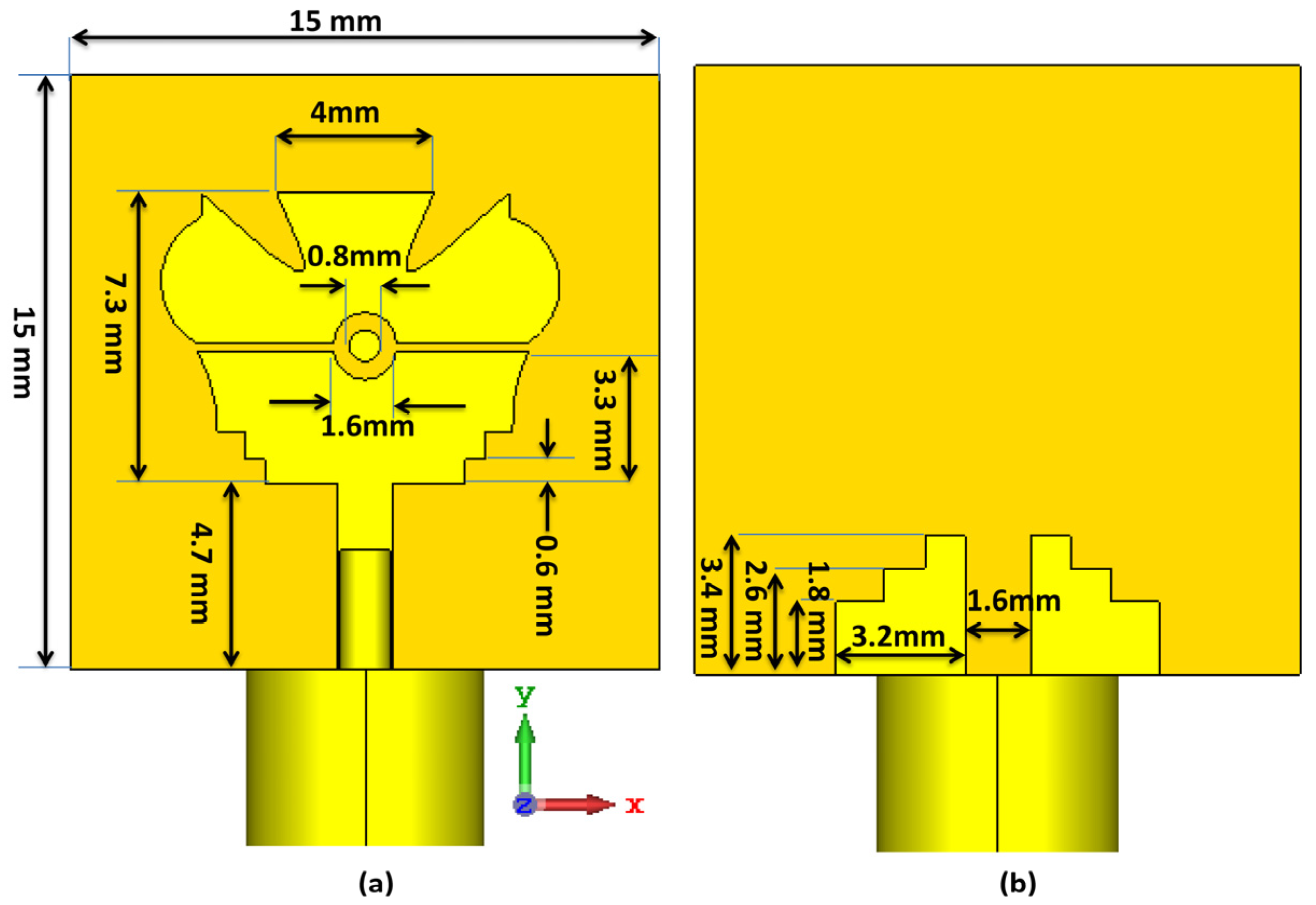
A very compact MIMO antenna was designed, simulated, fabricated, and tested in this paper. Decoupling structures are placed at the front and rear sides of the substrate, and long ground slots are introduced vertically on the partial grounds to introduce good isolation between the symmetrical ports. The suggested MIMO antenna covers the desired band for wideband communications with improved isolation greater than 20 dB over the achieved band. Moreover, the achieved radiation and diversity characteristics from the suggested antenna make it a good candidate for wideband MIMO communication systems.
3. 2-Port MIMO Antenna Design
In this section, a single antenna is copied to compose the 2 × 2 MIMO antenna, where antenna 2 is placed side-by-side with antenna 1 as shown in
Figure 3a. The spatial distance between the two radiators is 14.6 mm, and they are designed on the same substrate FR4 epoxy (ε
r = 4.4) with a total area of 15 × 30 mm
2. The insertion and return losses are investigated in
Figure 4a, and it can be noticed that the antenna succeeded in obtaining the desired frequency band with a range from 5.7 GHz to 11 GHz with S
11 below −10 dB and the lowest value of S
11 is −19 dB at 6.45 GHz; in addition, the obtained S
21 result is below −15 dB for the same achieved frequency band. Although the isolation is acceptable since it is below −15 dB, further enhancement is required, and it could be achieved by inserting decoupling stubs between the two radiators, as depicted in
Figure 3b. The presented decoupling stub is similar to an inverted fork with three rectangular slots of length 3.4 mm in the main fork arm (10.2 mm). The overall area of the decoupling stub is 4 mm × 14 mm, and two of these stubs are added on the top and the bottom layers of the substrate for improved isolation between the two radiators. The effect of the decoupling stubs on the two-port MIMO antenna performance is demonstrated in
Figure 4b. It can be observed that the achieved S
11 is below −10 dB from 6 GHz to 11 GHz with a minimum value of −18.5 dB at 6.6 GHz, and S
21 outcome is improved after using the fork-shaped stubs with a value below −20 dB starting from 6.4 GHz till the end of the obtained frequency band which confirms the positive influence of the newly added isolation stubs on the MIMO antenna outcomes. As well, the realized gain and the radiation efficiency with and without the decoupling stubs are displayed in
Figure 4c,d, which show that the antenna has gain fluctuated between 4 dBi and 5 dBi with decoupling stubs, from 3 dBi to 4 dB without stubs while the efficiency fluctuates from 80% to 95% with stubs and from 90% to 95% without stubs.
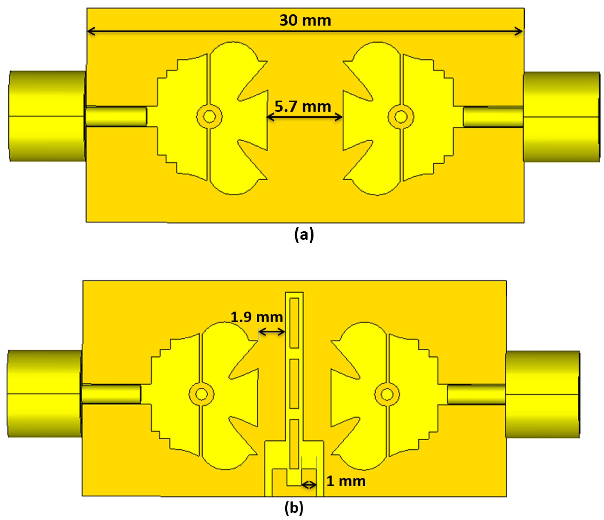
Another arrangement of the two MIMO radiators is utilized to investigate its influence on impedance-matching performance. The new arrangement is accomplished by putting the two radiators face-to-face within a constrained area of 15 × 30 mm
2, so the shortest distance between the two radiators is 5.7 mm, as demonstrated in
Figure 5a. The outcomes of the face-to-face two-port MIMO antenna are shown in
Figure 6a, and it is clear that the antenna covers the same frequency range (6–11 GHz) with S
11 = −21.5 dB at 7 GHz. Furthermore, the mutual coupling between elements is less than −18 dB over the obtained frequency band. In order to investigate the effect of the isolation stub used before, it will be inserted between the two radiators on the top and bottom sides of the substrate, as depicted in
Figure 5b. It is evident from the outcomes in
Figure 6b that the antenna radiates in the range from 6 GHz to 11 GHz efficiently, with a significant improvement in the mutual coupling between radiators of less than −20 dB over the achieved frequency band. As well, the realized gain and the radiation efficiency with and without the decoupling stubs are displayed in
Figure 6c,d, which show that the antenna has gain fluctuated between 1.5 dBi and 3.3 dBi for both cases while the efficiency fluctuates from 80% to 90% with stubs and from 92% to 95% without stubs.
From the introduced outcomes of the two-port MIMO antenna, it is worth noting that the two MIMO arrangements (side-by-side and face-to-face) provide distinct performance in terms of improved isolation in both cases after using decoupling stubs, besides their stable impact on the return loss outcomes, which are approximately similar to the outcome of a single antenna element. Consequently, the modified 2 × 2 MIMO antenna has a compact size with enhanced outcomes and can be extended to work with multiple ports utilizing the same two arrangements of isolation stubs due to their distinguished impact on the antenna performance. The forthcoming section introduces the 4 × 4 MIMO antenna with and without the isolation stubs, in addition to the implementation of the investigated arrangements for size reduction purposes with enhanced performance.
4. 4-Port MIMO Antenna Design
The two introduced arrangements in the previous section are used to achieve the four-port MIMO antenna since antenna 2 is placed beside antenna 1 (side-by-side), while antennas 3 and 4 are placed 180° with antennas 1 and 2 (face-to-face) as demonstrated in
Figure 7a. To enhance the coupling between the antenna elements, four pairs of stubs designed in the previous section are added on the top layer and the bottom layer of the substrate, as presented in
Figure 7b. These stubs work as isolators between the four radiators to reject any radiation of power between them. The effect of the decoupling stubs on the antenna performance is illustrated in
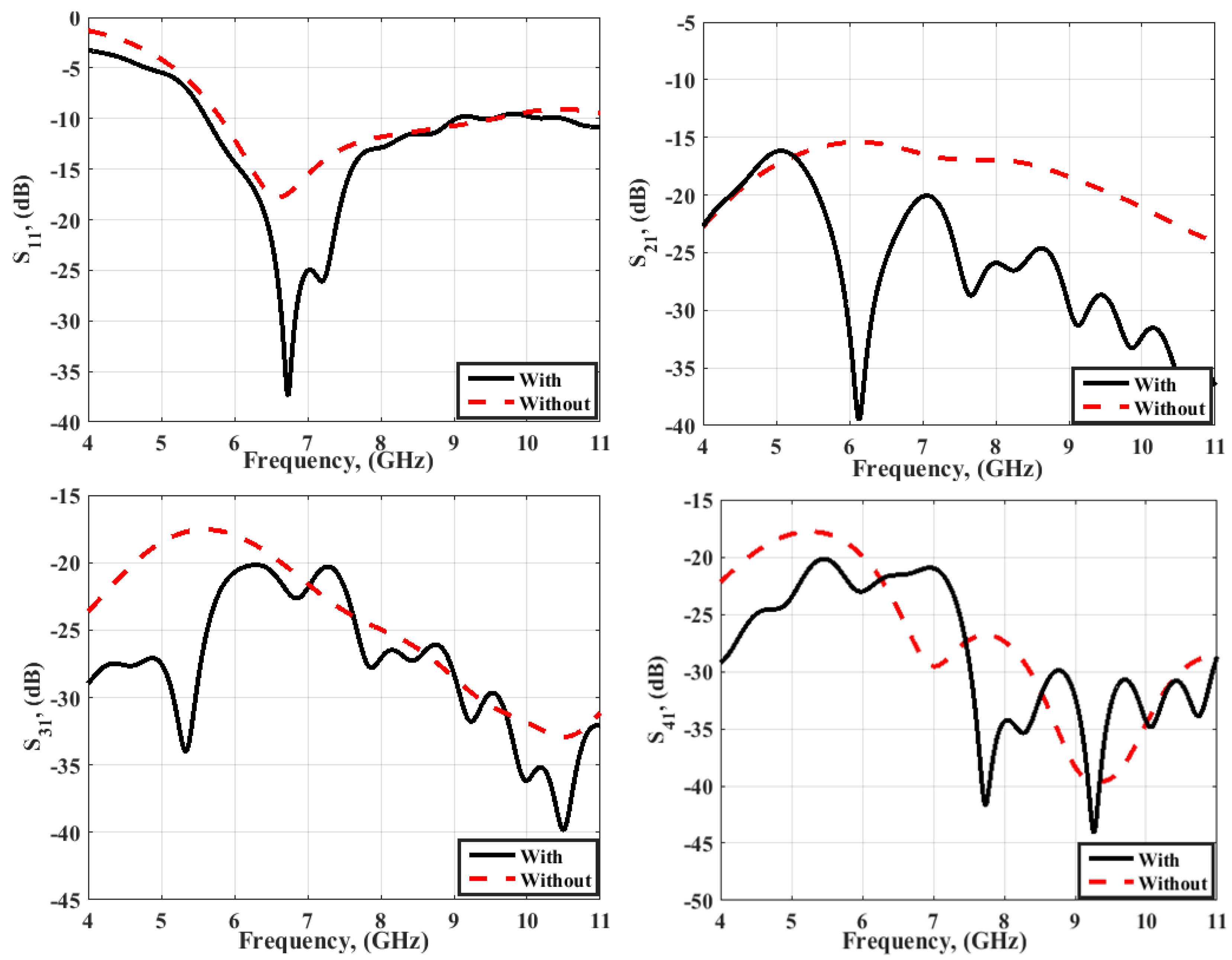
Figure 8. It can be noticed that the S
11 achieved the same outcomes in terms of impedance bandwidth, while the matching of the antenna is enhanced when the decoupling structures are used, as shown in
Figure 8. Additionally, the matching was −17.5 dB for the case without stubs at 6.7 GHz, and it turns to −37.5 dB at 6.8 GHz when the stubs are added, which proves the additive impact of the decoupling stubs on the impedance matching outcomes.
The S21 outcomes are also enhanced from −15 dB without the decoupling structure to less than −20 dB when the decoupling structures are utilized. The value of S21 is below −20 dB from 5.5 GHz till the end of the achieved band. Furthermore, S31 and S41 are improved from −17.5 dB to less than −20 dB after using the decoupling structures with a coverage of the whole obtained frequency band. So, these additional stubs have a significant effect on the impedance-matching performance of the suggested 4 × 4 MIMO antenna. It is worth noting that the antenna occupies an area of 30 × 30 mm2 with a very small distance between radiators (5.7 mm for face-to-face radiators and 7.6 mm for side-by-side radiators), which confirms the high level of compactness of the suggested antenna and its eligibility to be embedded in small portable devices.
The suggested MIMO antenna was experimentally fabricated on FR4 dielectric material of size 30 × 30 mm
2, as photographed in
Figure 9. Then, the model was experimentally measured using R&S ZVB 20 vector network analyzer (VNA) to test its impedance characteristics. Because of the antenna symmetry between ports, the results from one port were extracted, as illustrated in
Figure 10. It is noticed that the simulation results show that the antenna is well matched over the entire band spectrum from 5.75 up to 11 GHz, as shown in
Figure 10, while the measured results start from 5.8 GHz up to 10 GHz. There is a discrepancy between simulated and measured S
11 since there is a shift in resonance frequency of about 500 MHz (6.3 GHz measured and 6.8 GHz simulated), and this is due to the tolerance associated with fabrication and measurement. As well, the mutual coupling between ports has a value lower than −20 dB for both the simulation and tested outcomes, as shown in
Figure 6, with a relatively good trend between the two results. The S
21 outcomes are below −20 dB, starting from 5.7 GHz till the end of the achieved band. In addition, the S
31 outcomes are totally below −20 dB, except the measured result is above this level by 1 dB at 7 GHz only, and this tolerance may happen due to fabrication and measurement processes. Regarding the S
41 outcomes, both simulation and measurement outcomes are consistent with the same trend below −20 dB. After all these outcomes that compare the simulation and experimental work, it is evident that the suggested antenna is appropriate for diversified wideband MIMO applications due to its compact size, better matching, and improved isolation between the four ports.
In order to investigate the radiation characteristics of the suggested MIMO antenna with and without the decoupling stubs, the current distribution is carried out for that reason at two frequencies, 5.8 GHz and 9 GHz. To carry out the current distribution process in the proper way, the MIMO antenna is excited at port 1, while the other ports are terminated with 50 Ω matched loads. It is clear from the current distribution in
Figure 11 that a significant amount of current is distributed on port 2, and a tangible amount is shown on the two other ports for the case of no isolation, while a very small current is passing to the neighbor elements for the case of decoupling stubs. Furthermore, the majority of the current is distributed on the radiating element (port 1), which confirms the low mutual coupling between radiators and low power radiation from port 1 to the adjacent elements since the isolation stubs act as absorbers between the radiators. So, the decoupling stubs on the top and the bottom sides succeeded in mitigating the power transfer between the four elements.
In order to investigate the radiation characteristics of the suggested MIMO antenna, the antenna was mounted on the radiation characteristics setup inside the anechoic chamber, as shown in
Figure 12, to test its radiation patterns in different planes and the realized gain. It can be noticed from
Figure 12 that one port is excited, whereas the other ports are connected with matched loads of 50 Ω characteristics impedance. In addition, a horn antenna is mounted in the opposite side of the setup in order to perform the radiation measurements.
The simulated and measured normalized radiation patterns in both planes are illustrated in
Figure 13. It is clear that the antenna has an approximate omnidirectional pattern in one plane and a bi-directional pattern in the other plane at 5.8 GHz and 9 GHz, with a good match between the simulated and tested outcomes. The suggested MIMO antenna provides a radiation pattern similar to the pattern of a dipole antenna, which can be employed in various mobile applications due to the obtained radiation characteristics.
The antenna realized gain is considered one of the important parameters to validate the radiation performance of the suggested antenna, and it was carried out within the achieved operating frequency band, as illustrated in
Figure 14. The antenna has an average realized gain of around 4 dBi for the measured results since its minimum value is 2.5 dBi at 5.5 GHz and its maximum value is 4.75 dBi at 9.5 GHz. In addition, the average simulated realized gain is around 4.5 dBi with a minimum value of 3.1 dBi at 5.4 GHz and a maximum value of 5.25 dBi at 9.6 GHz. Furthermore, the two results are in good consistency with slight variation because of the fabrication and measurement tolerance.
In order to evaluate the MIMO characteristics of the proposed four-port antenna, this evaluation can be accomplished through the investigation of different parameters such as envelop correlation coefficient (
ECC), diversity gain (
DG), and mean effective gain (MEG). The
ECC measures the amount of correlation between antenna radiators and it can be extracted from radiation patterns as from Equation (1) [
20,
21].
The simulated and tested outcomes of the
ECC at port 1 are illustrated in
Figure 15. The
ECC has values less than 0.004 inside the obtained frequency band, which are lower than the accepted limits of the
ECC (≤0.5), with a good trend between the two results. The
DG is another parameter that can be calculated to investigate the MIMO diversity capability of the suggested model, and it has higher values when the correlation between radiators is low. The
DG can be calculated from Equation (2) which has a direct relation with
ECC [
21]. As illustrated in
Figure 16, the
DG achieved values greater than 9.97 dB inside the operated frequency range, which reflects the distinct isolation between the radiators.
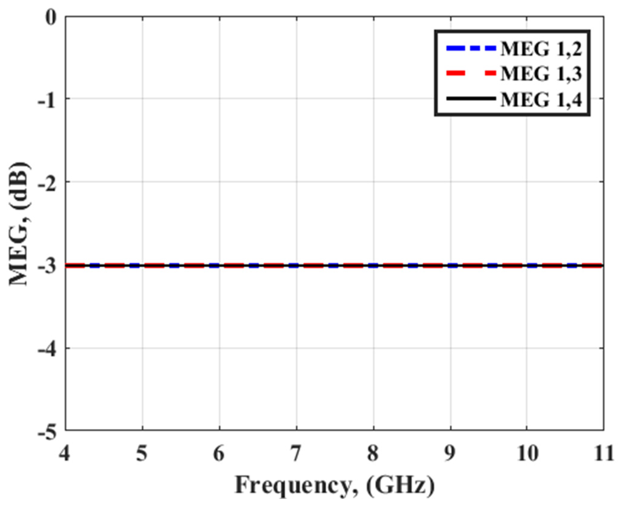
Mean effective gain (MEG) is another parameter that can be used to test the diversity capability of the suggested 4-port MIMO antenna. It is defined as the ratio of the received amount of power by the proposed MIMO antenna to the received one by an isotropic antenna, and it can be evaluated using (3), where
P is the number of antenna ports [
22]. It is worth noting that the ratio between
MEGi and
MEGj should not be higher than −3 dB, and this is evident by the presented result in
Figure 17. Finally, the channel capacity with respect to signal-to-noise ratio (SNR) is added in
Figure 18 for the two-port and four-port MIMO antenna. It is evident from
Figure 18 that the 4 × 4 MIMO antenna has an improved channel capacity when compared to 2 × 2 MIMO antenna, and for that reason, we adopted and fabricated the four-port MIMO antenna in the current work.
To evaluate the performance of the suggested MIMO antenna, a comparative study between our MIMO antenna and the lately reported antenna is demonstrated in
Table 1. The comparison is performed in terms of the number of ports, size, bandwidth, isolation, and
ECC. It can be noticed from the presented table that the suggested antenna outperforms the other MIMO antenna models since it has a very compact size that accommodates four radiators for improved impedance and radiation characteristics. Consequently, all these advantages confirm the suitability of the suggested four-port MIMO antenna for handheld devices that operates in various wideband applications.


