Abstract
In this paper, a set of transmission schemes are proposed for the delivery of multicast (MC) signals, in which an intelligent reflecting surface (IRS) assists the transmission from an access point (AP) to a set of multicast users. It is known that the large number of IRS reflecting elements have the potential to improve the transmission efficiency by forming an artificial signal path with strong channel gain. However, the joint optimization of the AP beamformer and the phases of the IRS reflecting elements is challenging due to the non-convex nature of the phase elements as well as the high computational complexity required for a large number of elements. A set composed of two AP beamformer schemes and a set with two IRS phase adjustment algorithms are proposed, which are sub-optimal but less computationally demanding. A semi-definite relaxation (SDR)-based scheme is considered along with a least squares (LS) based one for the AP beamformer design. For the IRS phase adjustment, an LS based optimization and a grouping method for the phase elements are suggested. From these two sets, four combinations of overall optimization can be built, and their performances can be compared with their merits and weaknesses revealed. The signal-to-interference-plus-noise power ratio (SINR) performance results are verified in various parameter conditions by simulation.
1. Introduction
While cellular systems are basically designed for access points (APs) to deliver separate messages for individual users, multicast (MC) transmission techniques supplement the basic mode by allowing the AP to distribute common messages to groups of users [1,2,3]. Since the weakest channel among the user channels served by the same message determines the throughput of the MC channel, the optimal beamforming for the multiple antennas at the AP is known to be the semi-definite relaxation (SDR) approach [1,2], which may cause excessive computational load as the transmit antenna number at the AP grows. For the multi-cell environment, coordinated beamforming supports multi-group (MG) MC as well [3]. The optimization of MC for massive-scale antenna array systems in millimeter-wave bands is considered in [4,5], including the MG MC cases [6,7,8]. To improve the wireless transmission channels, multiple input, multiple output (MIMO) techniques with multiple antennas have long been considered and applied in cellular standards. These techniques have recently extended into massive MIMO systems with large numbers of antenna elements, where hybrid analog-and-digital beamforming (BF) techniques [9,10,11,12,13] are suggested to compromise the implementation cost and complexity. Hardware-intensive radio frequency (RF) chains are limited to few channels for digital BF, which are tied to analogue BF arrays with phase shifters for the large number of antenna elements. These hybrid BF systems are required to reside in the transmitters and receivers, and thus may still lead to an excessive amount of hardware and associated cost. On the other hand, intelligent reflecting surfaces (IRSs), intentionally installed near wireless transmission channels, form artificial transmission paths [14,15,16,17,18,19,20] and are introduced to improve wireless links by reflecting incoming signals and providing additional signal paths toward the user terminals. In effect, the analogue BF arrays of hybrid BF systems are pushed to the far corners of the networks in IRSs so that they may be comparable to relay systems. Unlike the signal-processing-intensive and power-hungry relay systems, however, IRS-assisted transmissions achieve very close performance to that of relay networks in removing the shadowed areas [21,22,23,24] of cellular networks when there are enough reflecting elements deployed at the IRS. Note that this remarkable benefit comes at the cost of installing devices around the networks with relatively light computational resources and power consumption.
Transmission systems with training methods are presented in [25,26], and application in the millimeter band is considered in [27]. Multicasting systems with IRS support are considered in [28,29]. Analogous to the BF in multi-antenna systems, the adjustment of the phase shifters of IRS reflecting elements is the key technical challenge regarding IRSs [14,15,16,25,26]. An alternative approach for the optimal phase adjustment of a single user link is presented in [16], where the alignment of all phases of the paths through the IRS to the phase of the direct channel from the base station to the user is shown to be optimal. The collaborations of the IRS and various relay systems are considered [21,22,23,24]. The outage performance of an IRS-assisted multicasting system is presented with a random phase adjustment at the IRS in [28]. Here, we consider an MC network, where the user links from the AP are assisted by the reflections from an IRS with a set of joint BF at the AP and the phase alignments at the IRS. The BF adjusts the complex weights of the multiple antennas such that the AP transmission is optimized for a certain metric while the IRS reflection is controlled by determining the phase shifter values of reflecting elements. Just like the analogue BF in a hybrid BF system, the phase shifters of the IRS are constrained to be complex phasers, and this fact makes the associated optimizations hardly convex. Therefore, optimal joint BF and phase adjustment does not lend itself to an easy solution, and some suboptimal and practical approaches to this problem are needed. In this paper, we propose two AP BF schemes and two IRS phase adjustment schemes, from which four (2 × 2) combinations of alternating schemes are presented and their performances are compared in various parameter settings.
A SDR-based scheme is proposed for the AP BF, though it is already known to be the optimal one for the MC channel without IRS. Additionally, least squares (LS)-based algorithms that try to equalize user channel strengths are proposed for the AP BF and the IRS phase alignment, respectively. These schemes require a less-demanding computational load compared to the SDR scheme when the number of reflecting elements and/or the number of AP antennas becomes large. Finally, a grouping algorithm of IRS elements is proposed for the IRS phase alignment, where each IRS reflecting element is associated to a specific user to strengthen the paths toward the user. A similar idea is applied to the multiuser channel with an IRS support in [19]. Although the SDR scheme is optimal, it requires high computational load when the dimension of the signal vector increases. On the other hand, the other three are sub-optimal with reasonable computation, and thus are good candidates for practical implementation.
This paper is organized as follows. In Section 2, the system model of the proposed multi-antenna MC channel with an IRS is presented. Alternation-based beamforming designs are presented in Section 3. After presenting the corroborating numerical results in Section 4, Section 5 concludes this paper. Notations: The notations , , , , and are the Hermitian transpose, the pseudo inverse, the transpose, the conjugate and the trace of a matrix , respectively. and denote the absolute value of a and the norm of , respectively. The notation denotes the all-one vector with J elements and generates a vector whose nth element is the phase of the nth element of with unit magnitude. represents the th element of ; represents the i-th element of vector ; returns a vector whose elements are the diagonal elements of the matrix and returns a diagonal matrix with the elements of the vector as its diagonal entries. denotes a complex white Gaussian random vector with zero mean vector and the covariance matrix . takes the expectation of a and returns the phase vector of a complex vector . The function returns the maximum singular value of the matrix . The operator returns the .
2. System Model
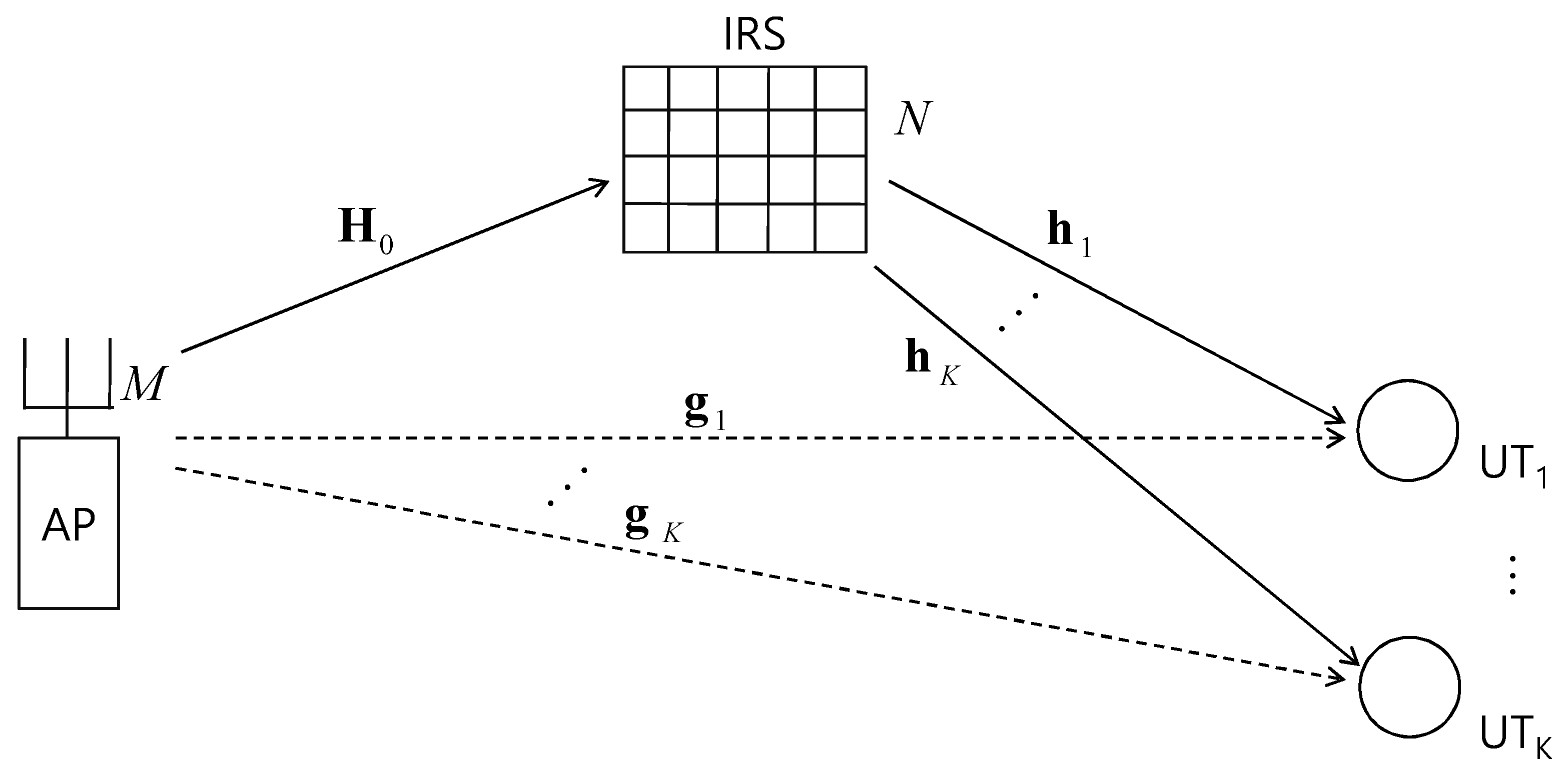
Figure 1 depicts a system model where an access point (AP) sends a multicast message to K user terminals (UTs), while an IRS assists the direct AP transmission by reflecting the signal from the AP toward the UTs. Each UT receives signals that include a common message simultaneously from the AP and the IRS. The AP and each UT have M antennas and a single antenna, respectively, while the IRS is equipped with N reflecting elements. The multiple input, multiple output (MIMO) channel from the AP to the IRS is denoted by an matrix . The multiple input, single output (MISO) channel from the AP to the kth UT (i.e., ) is denoted by an vector and the MISO channel from the IRS to the jth UT (i.e., ) is denoted by an vector . The elements of these matrices and vectors are independent and identically distributed as .
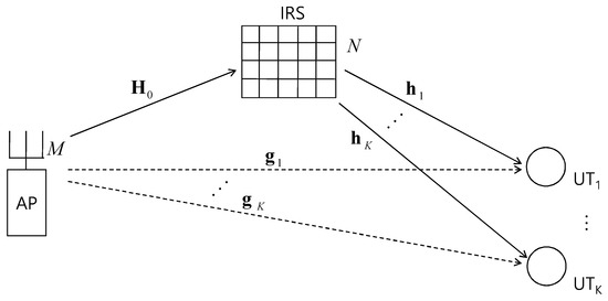
Figure 1.
Multicast channel with an AP, an intelligent reflecting surface (IRS) and K user terminals (UTs).
The AP transmits signal through M antennas, where is an pre-coding vector with and x is the common multicast message signal for K UTs with the transmit power . The transmitted signal from AP is delivered to the UTs through the direct link from the AP and the secondary link through the IRS, where the two signals are added up at the UTs. The phase-shifting at IRS is modeled as an complex diagonal matrix , where the i-th diagonal element with . The received signals of are written as follows:
where represents the attenuation at the IRS which is uniformly applied to all the IRS elements. The rate of x is R bits per second per channel use; is the additive noise signals at with distribution. Without loss of generality, we can set . The signal-to-noise ratio at is then given as
with the mutual information (MI) at as . For the MC transmission, the user with minimum MI among the K MC users determines the rate, and the logarithmic function possesses monotonic relation with its argument. Therefore, the MC transmission rate R can be maximized by maximizing or, equivalently,
The optimization of the objective function in (3) involves the vector and the diagonal matrix , where the unit magnitude constraint of makes the problem non-convex and demanding at the same time. Problems with sets of parameters, as in this case, are often handled by alternating approaches, where each set of parameters is optimized with the other sets being fixed. With fixed, the optimization of is well-studied in the context of multicast beamforming, and the near-optimal solution can be found by an SDR-based method [1,2]. Although the SDR approach is widely applied, providing effective solutions to many classes of problems, it requires demanding computational complexity. On the other hand, with a fixed , the authors of [16] show that the maximization of can be achieved by making ’s phase shifters so that they align all the phases of the added terms in . Here, the problem at our hands is maximizing , which complicates the direct application of the method in [16] and thus motivates the authors to propose novel algorithms to determine based on the method of [16]. We assume that all the channel status information (CSI) is available through some pilot training procedures.
3. Beamformer Design
Here, we propose two schemes for the alternating optimization of and , maximizing the metric in (3). We begin by recalling the SDR-based optimal beamforming for the multicasting system, which corresponds to the optimization of with a fixed in (3). Defining
and , (3) turns into
where the SDR-based solution has been well-known for many years [1,2] with the introduction of semi-definite matrix in place of and following the rank-reduction process. Here, can be adjusted to make the magnitude of found to one. Since the SDR approaches of (4) require a demanding amount of computation, an alternative method with reduced complexity is proposed as the second scheme, which utilizes the least squares (LS) rule to equalize the gains of all user channels.
Then, two algorithms to determine the IRS phase shifters are proposed such that we create two sets of algorithms for finding the AP pre-coder and for finding the IRS phase shift matrix , respectively. Overall, four optimizations can be conducted in an alternating manner between the SDR method or the LS method and Algorithm 2 or Algorithm 3 to be presented for the IRS phase adjustment. Here, the alternation starts either with the SDR method or with LS with a whose diagonal elements have random phases. The SDR method and the LS method produce unit magnitude AP pre-coders , while Algorithm 2 and Algorithm 3 output the IRS phase shift matrices , where each of two methods in a combination rely on the results of the other method in the same combination.
3.1. LS-Based AP Pre-Coder Optimization
For the LS-based problem formation, we need the following definition of a matrix as . For a certain signal level , we consider the following magnitude-constrained LS estimation problem as
By introducing vector as the estimation target signal, we turn the LS estimation into an equalization problem, where the signal levels at the MC UTs are almost uniformly equalized with the LS criterion. The solution of (5) can be found through the approach of [30], as follows. First, we define
For a positive , the LS estimate of with the magnitude constraint is achieved with
The LS formulation above results in the determination of depending on the signal level as in (6), which makes the decision a sub-part of optimizing . For the optimization of , we define
and the square of the LS estimation error is given as
The above LS-based equalization allows us to consider the following equalized signal level as , which is an increasing function of until the point is reached since is a proportional fraction of for the interval. However, it is easy to show that increases faster and approaches as grows beyond . Therefore, the overall shape of over is assured to be concave, and the maximum of the equalized signal level can be obtained at by conducting the golden section search (GSS) over within the feasible range of . This makes the overall optimization a concave one of , as summarized in Algorithm 1, where the AP beamformer is found as a by-product.
| Algorithm 1: AP pre-coder optimization algorithm |
|
3.2. IRS Phase Adjustment
In this subsection, we consider the optimization of the diagonal matrix at the IRS with the AP pre-coder fixed. We provide two methods, where one is based on the LS method as in the previous subsection and the other one relies on an intuitive approach derived from the optimal phase alignment of [16]. The latter method associates each IRS reflection element with a user so that the elements are separated into few groups. A similar idea is applied in [19], where the multiuser channel with an IRS support is considered. With the definition and for , we can modify the problem (3) as
For , the authors in [16] show that phase alignment among the different channel paths passing through the IRS so that they are all aligned to the phase of achieves the optimal beamforming for . In other words, or is the necessary condition required for . Since this rule is difficult to apply for all user channels at the same time where , a modification of the method is required to reflect the minimum operation in (7), and thus the rule is to be compromised and shared among different user channels. Note that the phase alignment of [16] is equivalent to the equal gain combining (EGC) of diversity combining.
First, we apply the LS method as we did in Section 3.1 to find the matrix , although it is constrained to be a diagonal matrix with unit magnitude elements. With the definitions of the phase vector from the diagonal elements of as and , the right-most term in (7) can be re-written as . Then, we can form the following LS estimation problem of .
Here, the matrix is composed of ’s on its rows. Note that the elements of are not yet constrained to be unit magnitude to apply the LS method in (8), and the constraint will be applied at the final stage. Again, we can define
For a positive , the LS estimate of with the magnitude constraint is given as
Again, the decision is dependent on and we now turn to the optimization of . Defining
the square of the LS estimation error is given as
As in Section 3.1, the equalized signal level is an increasing function of until the point is reached. Again, the overall shape of over is assured to be concave and the maximum of the equalized signal level can be obtained at by conducting the GSS over within the feasible range of . Finally, we take only the phases the elements of found , while discarding the magnitude components of the vector as . Again, the overall optimization is a concave one of as summarized in Algorithm 2, where the IRS phase shift vector is found as a by-product after discarding the magnitude values and leaving only the phase values.
| Algorithm 2: AP pre-coder optimization algorithm |
|
Second, we provide a user grouping approach, with the optimal phase alignment of [16] applied to each group. The minimum operator in (7) not only prevents any user from controlling the IRS exclusively, but also forces the user channels to be handled on an equal basis. Therefore, one reasonable approach in this case is a round-robin method, where each user is allowed to take up the IRS in turn to pick up a few IRS antenna elements with the strongest gain paths among the previously unselected antenna elements, and to adjust the phases of the selected paths as in [16]. This process is repeated until the all IRS antenna elements are selected, that is, each element falls in a territory among K user channel territories. In this way, all K user channels have equal opportunity to share the IRS and to apply the algorithm of [16] with approximately IRS antenna elements. At each round of IRS antenna selection, the number of selected elements is determined to minimize the disparity among the sums of user channel gains selected so far. After all the IRS antenna elements are determined to fall in selected territories, the sums of the aligned channel gains of user channels are approximately equal. The above decision scheme is summarized in Algorithm 3. To save computation, we may apply the Algorithm 3 until some number of elements less than N are selected, and leave the remaining unselected ones with random phases, leveraging the fact that the added channel gain suma from these elements are averaged out by the randomness. The method introduced in [19] first uses a simple mathematical model to define the numbers of elements in the groups and allocates the reflecting elements in a block-wise manner according to the defined number of elements. On the other hand, Algorithm 3 allocates reflecting elements one-by-one into groups in a round-robin fashion while it checks out the channel gains accreted so far to keep the final channel gains as uniform as possible. Therefore, it is expected that Algorithm 3 is superior to the method in [19] in equalizing the channel gains. However, the comparison of these two methods in the problem setting of this work is beyond the main concerns of this paper, and thus is skipped.
As a result of Algorithm 3, each user allocates about IRS antenna elements with the best channel gains into its phase control territory so that all the channels through these elements are coherently added to the direct channel from the AP, resulting in the maximized sum channel gains while the sum channel gains among the K users are almost equalized. The remaining IRS antenna elements of size about outside of a user’s territory belong to other users’ territories so that their phases can be taken as randomly aligned for the particular user’s point. In this case, the methods of order statistics [31] can be applied to analyze the impact of the above IRS beamforming. However, this approach is very tedious and does not produce easy and intuitive results, and we thus instead take an approximation approach to the channel gains through the IRS. Suppose a selection scheme where each user picks up the best channel among K independent identically complex Gaussian-distributed channel realizations. The resulting channel gain of this scheme is [32], where is the gain of an individual channel. Combining this with the result of Proposition 2 of [16] and the fact that only IRS elements are aligned, the approximate channel gain approaches as N goes to the infinity. Compared to the result of [16], the channel sharing loss is reflected as , while the loss is compensated by the selection as appears in the term .
| Algorithm 3: decision algorithms |
|
4. Numerical Results
In this section, we present numerical results based on the SNR performance of the proposed optimization combinations in various parameter settings. An AP equipped with M antennas serves K multicast users, while an IRS with N reflecting elements is supporting the AP transmission. Four combination schemes are considered alongside two reference schemes denoted as SDR and LS (Algorithm 1) in the legends, where only the SDR algorithm and only Algorithm 1 are applied for the AP without the phase optimization of the reflecting elements at the IRS. The last two have the role of baseline schemes for the four combinations proposed.
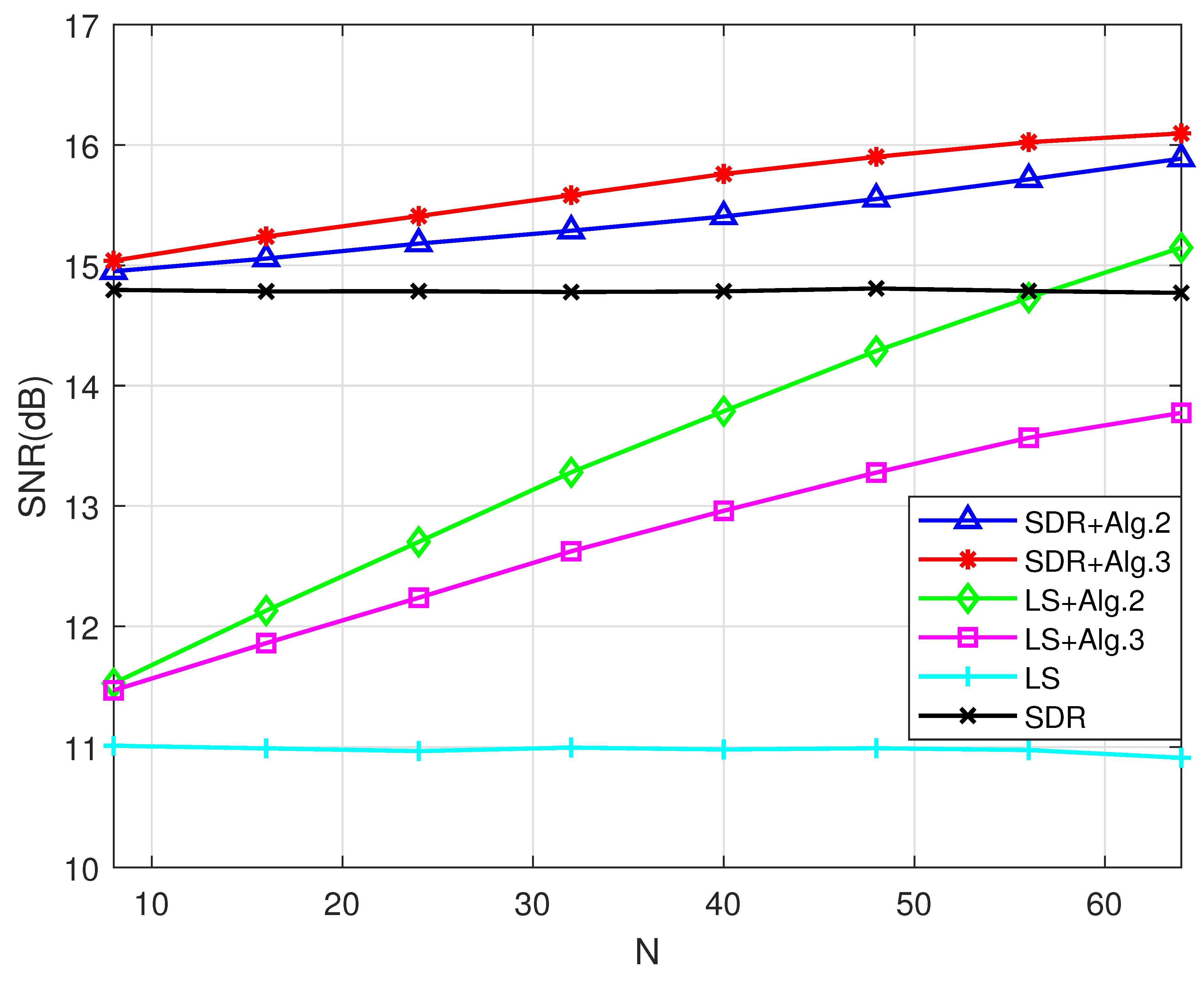
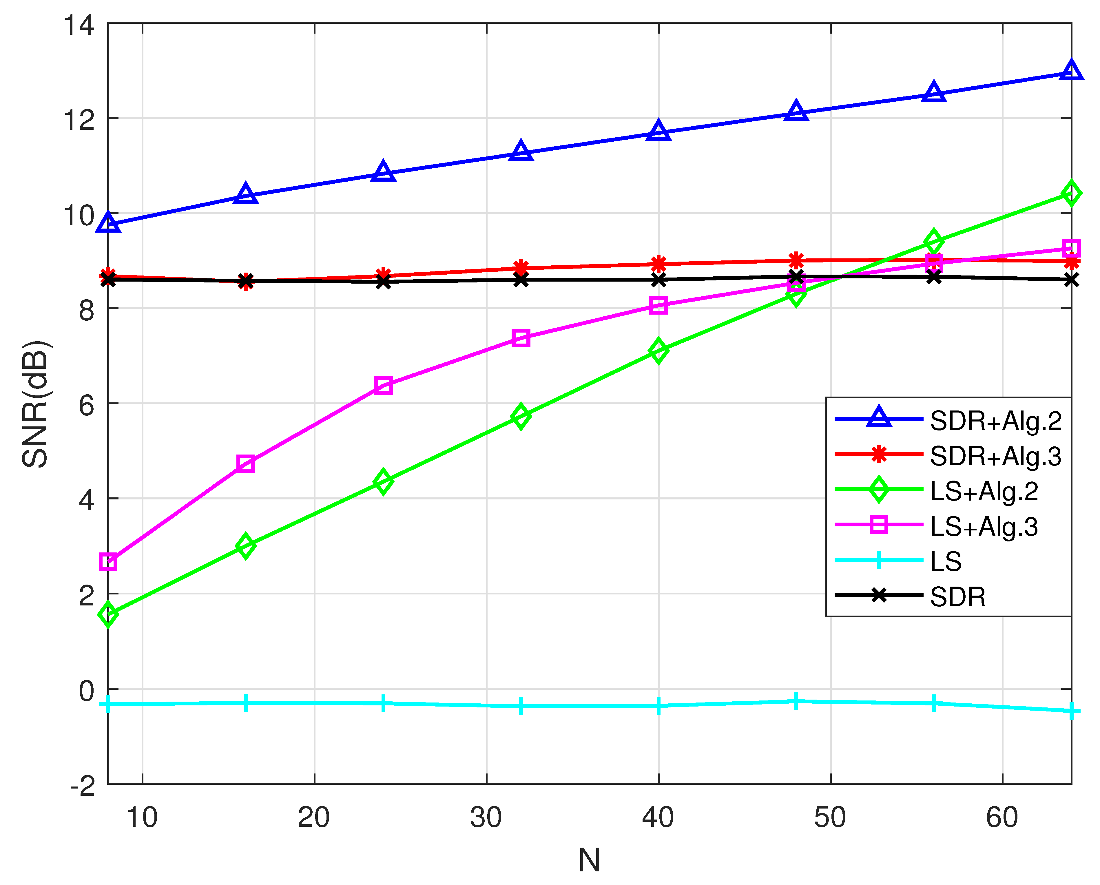
Figure 2 and Figure 3 display the SINRs of the various schemes in this paper over the variation of the number of IRS reflecting elements in the under-loaded case (Figure 2) and in the overloaded case (Figure 3), respectively. Note that the transmit power is fixed at with eight transmit antennas () at the AP, where the transmit power is set to the relative received power value compared to the additive noise power at the receiver, and it reflects the combination of actual transmit power and the loss through the path. The flat curves correspond to the SDR-only scheme and the LS-only scheme, while these schemes do not utilize the increasing number of reflecting elements (N) at the IRS in their performance enhancement since the diagonal elements of matrix are set to have random phases. On the other hand, all four proposed schemes exploit the increased number of IRS reflecting antennas, but the efficiency is differentiated depending on N and the scenarios (cases). In both cases, the SDR-only and the LS-only schemes show large SNR gaps, which creates SINR disparities among the group of schemes depending on the AP pre-coder type. Comparing the performance of the IRS phase alignment schemes (Algorithms 2 and 3), their performances vary depending on the combined AP pre-coder type and the scenario. In the under-loaded case in Figure 2, the SDR AP pre-coder does better with Algorithm 3 than with Algorithm 2, while the LS case shows the opposite trend. In the overloaded case of Figure 3, this trend shows the reverse trend, while the curves involved with Algorithm 3 saturate with large N values. This observation indicates that the Algorithm 3 grouping of the IRS reflecting elements does not efficiently handle the cases with large numbers of users compared to Algorithm 2, where the LS-based IRS phase adjustment is applied. Overall, Algorithm 2 shows competitive performance regardless of the AP pre-coding scheme and the scenario. On the other hand, Algorithm 3 combined with LS performs well when the number of IRS reflecting elements N is low in the overloaded case, while it performs well regardless of N in the under-loaded case.
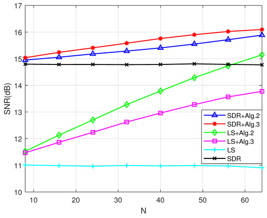
Figure 2.
SINR performance comparison over the number of reflecting elements N in the under-loaded case. Here, and .
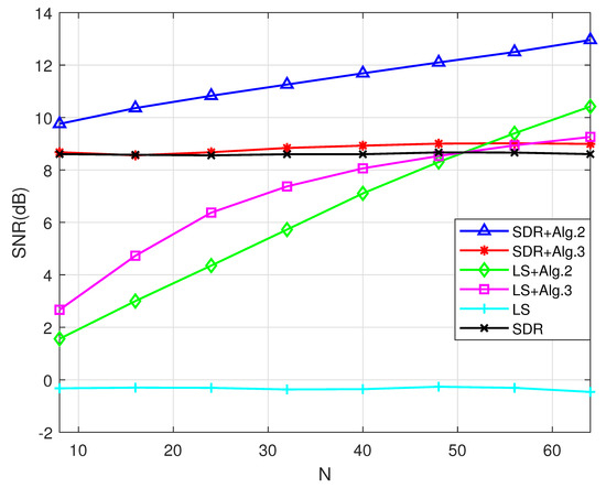
Figure 3.
SINR performance comparison over the number of reflecting elements N in the overloaded case. Here, and .
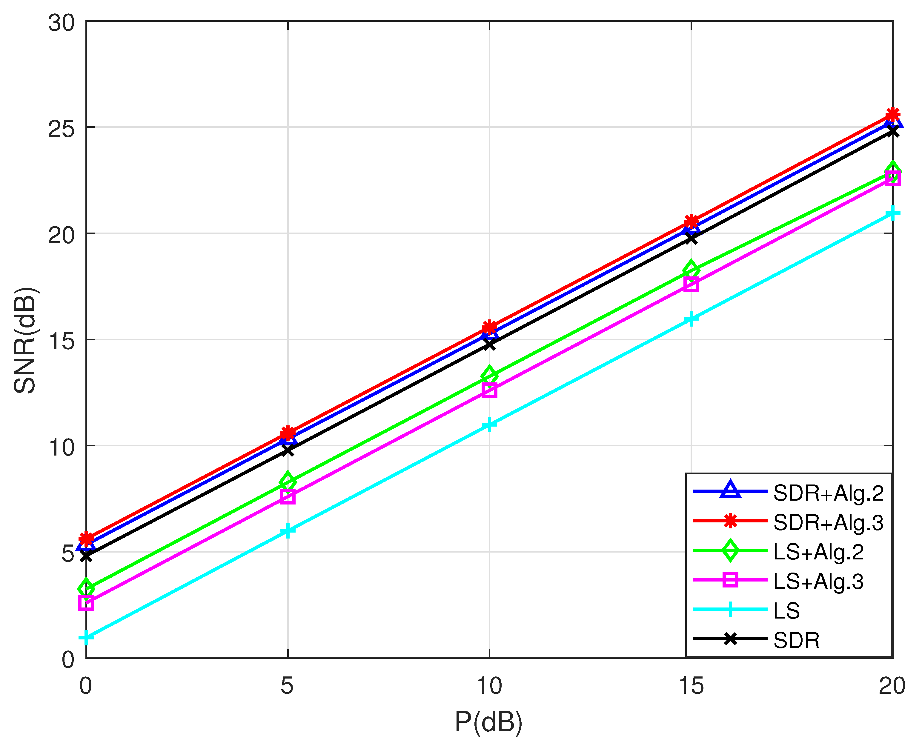
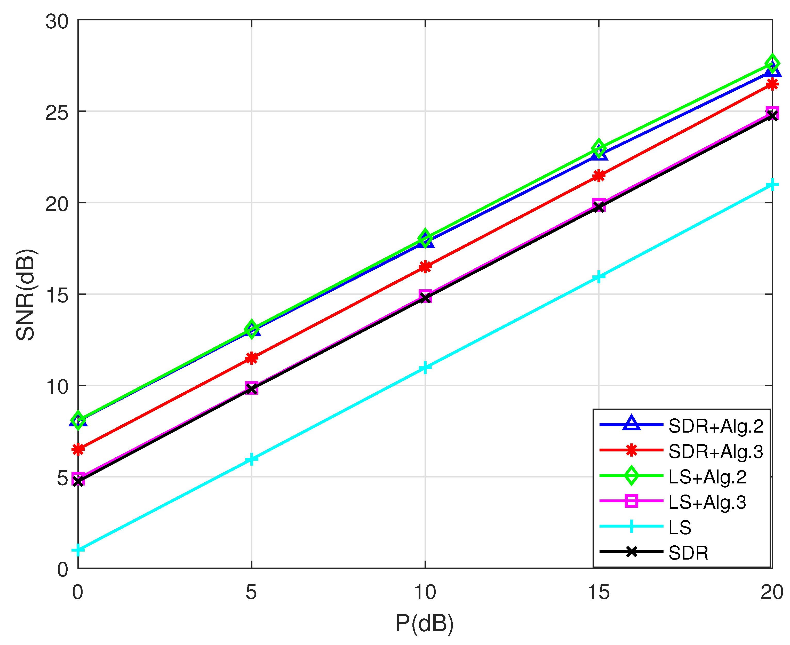
In Figure 4 and Figure 5, the SNR results of the proposed schemes over the variation of the transmit power P are compared in the under-loaded case, where the number of IRS reflecting elements is small () in Figure 4 and is large () in Figure 5. The SNR and the transmit power are expected to have linear dependence in the log scale, while the parallel gaps between different schemes reflect the power gains of the schemes. Again, all four proposed schemes exploit the increased transmit power, while the efficiency differs depending on N and the scenarios (cases). Additionally, the SDR-only scheme and the Algorithm 1-only scheme are base-line schemes for the other combination schemes. It is easy to see that Algorithm 2 widens the gap with Algorithm 3 as N increases, regardless of the AP pre-coder optimization they are combined with. Note that Algorithm 1, for the AP pre-coder optimization, becomes comparable to the SDR scheme as N becomes large, and thus the combination of Algorithms 1 and 2 is a reasonable solution when N is sufficiently large, which is also observable in Figure 2.
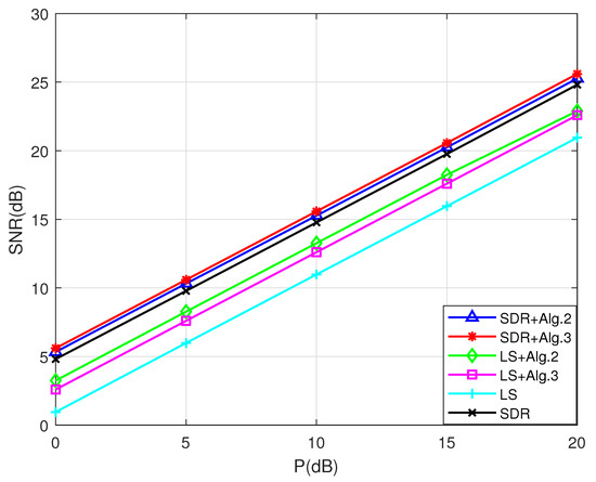
Figure 4.
SINR performance comparison over the transmission power P with a small number of reflecting elements (). Here, and .
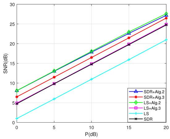
Figure 5.
SINR performance comparison over the transmission power P with a fair number of reflecting elements (). Here, and .
5. Conclusions
Herein, we considered the optimization of an access point (AP) beamformer and IRS phase adjustment in a multicast network with an intelligent reflecting surface (IRS) assist. Two computationally efficient AP beamforming schemes and two IRS phase adjustment algorithms were proposed, comprising four combinations of joint optimization schemes. Semi-definite relaxation (SDR) and least squares (LS) equalization were considered for the AP beamformer and the LS equalization, and grouping methods were suggested for the IRS phase adjustment. From these two sets, four combinations of joint optimization were built and their performances were compared to discuss their associated strengths and weaknesses. All combinations utilized the increased transmit power and the increased number of IRS reflecting elements in their performance enhancement, but their efficiency differed. Computationally competitive LS-based combination showed comparable performance that matched that of the SDR-based scheme, which had a relatively heavy computational load that increased as the transmit power or the IRS reflecting element number grew. On the other hand, the LS and the grouping of reflecting elements combination showed merit in the case of heavily loaded users with small numbers of reflecting antennas.
Author Contributions
D.H. proposed the beamforming principles and associated algorithms for the MC NOMA wireless networks; J.Y. and S.S.N. helped to improve the algorithms, and derived and analyzed all simulation results. Additionally, H.-K.S. provided the experimental materials for better computational simulation and revised critical errors of the manuscript. All authors have read and agreed to the published version of the manuscript.
Funding
This research was supported in part by the MSIT (Ministry of Science and ICT), Korea, under the ITRC (Information Technology Research Center) support program (IITP-2022-2018-0-01423) supervised by the IITP (Institute for Information & Communications Technology Planning & Evaluation), by the National Research Foundation of Korea (NRF) grant funded by the Korea government (MSIT) (NRF-2021R1F1A1047271).
Institutional Review Board Statement
Not applicable.
Informed Consent Statement
Not applicable.
Data Availability Statement
Not applicable.
Conflicts of Interest
The authors declare no conflict of interest.
References
- Sidiropoulos, N.; Davidson, T.N.; Luo, Z. Transmit beamforming for physical-layer multicasting. IEEE Trans. Signal Process. 2006, 54, 2239–2251. [Google Scholar] [CrossRef]
- Chang, T.; Luo, Z.; Chi, C. Approximation bounds for semidefinite relaxation of max-min-fair multicast transmit beamforming problem. IEEE Trans. Signal Process. 2008, 56, 3932–3943. [Google Scholar] [CrossRef]
- Xiang, Z.; Tao, M.; Wang, X. Coordinated multicast beamforming in multicell networks. IEEE Trans. Wireless Commun. 2013, 12, 12–21. [Google Scholar] [CrossRef]
- Tran, L.; Hanif, M.F.; Juntti, M. A Conic Quadratic Programming Approach to Physical Layer Multicsting for Large-Scale Antenna Arrays. IEEE Signal Process. Lett. 2014, 21, 114–117. [Google Scholar] [CrossRef]
- Wang, J.; Xu, H.; Zhu, B.; Fan, L.; Zhou, A. Hybrid Beamforming Design for mmWave Joint Unicast and Multicast Transmission. IEEE Commun. Lett. 2018, 22, 2012–2015. [Google Scholar] [CrossRef]
- Wang, Z.; Ma, Y.; Li, H.; Li, M.; Liu, Q. Efficient Hybrid Beamforming for Multi-Group Multicasting in mmWave Systems. In Proceedings of the 11th International Conference on Wireless Communications and Signal Processing (WCSP), Xi’an, China, 23–25 October 2019. [Google Scholar]
- Abanto-Leon, L.F.; Hollick, M.; Sim, G.H. Hybrid Precoding for Multi-Group Multicasting in mmWave Systems. In Proceedings of the 2019 IEEE Global Communications Conference (GLOBECOM), Waikoloa, HI, USA, 9–13 December 2019. [Google Scholar]
- Sadeghi, M.; Bjornson, E.; Larsson, E.G.; Yuen, C.; Marzetta, T.L. Max–Min Fair Transmit Precoding for Multi-Group Multicasting in Massive MIMO. IEEE Trans. Wireless Commun. 2018, 17, 1358–1373. [Google Scholar] [CrossRef]
- Heath, R.W.; Gonzalez-Prelcic, N.; Rangan, S.; Rho, W.; Sayeed, A.M. An Overview of Signal Processing Techniques for Millimeter Wave MIMO Systems. IEEE J. Sel. Top. Signal Process 2016, 10, 436–453. [Google Scholar] [CrossRef]
- Han, S.; Xu, C.I.Z.; Rowell, C. Large-Scale Antenna Systems with Hybrid Analog and Digital Beamforming for Millimeter Wave 5G. IEEE Commun. Mag. 2015, 53, 186–194. [Google Scholar] [CrossRef]
- Molisch, A.F.; Ratnam, V.V.; Han, S.; Li, Z.; Nguyen, S.L.H.; Li, L.; Haneda, K. Hybrid Beamforming for Massive MIMO: A Survey. IEEE Commun. Mag. 2017, 55, 134–141. [Google Scholar] [CrossRef]
- Alkhateeb, A.; Ayach, O.E.; Leus, G.; Heath, R.W. Channel Estimation and Hybrid Prcoding for Millimeter Wave Cellular Systems. IEEE J. Sel. Top. Signal Process. 2014, 8, 831–846. [Google Scholar] [CrossRef]
- Ayach, O.E.; Rajagopal, S.; Abu-Surra, S.; Pi, Z.; Heath, R.W. Spatially Sparse Precoding in Millimeter Wave MIMO Systems. IEEE Trans. Wirel. Commun. 2014, 13, 1499–1513. [Google Scholar] [CrossRef]
- Wu, Q.; Zhang, R. Beamforming Optimization for Intelligent Reflecting Surface with Discrete Phase Shifts. In Proceedings of the ICASSP 2019—2019 IEEE International Conference on Acoustics, Speech and Signal Processing, Brighton, UK, 12–17 May 2019. [Google Scholar]
- Hu, S.; Rusek, F.; Edfors, O. Beyond Massive MISO: ThePotential of Data Transmission With Large Intelligent Surfaces. IEEE Trans. Signal Process. 2018, 66, 2746–2758. [Google Scholar] [CrossRef]
- Wu, Q.; Zhang, R. Intelligent Reflecting Surface Enahnced Wireless Network via Joint Active and Passive Beamforming. IEEE Trans. Wireless Commun. 2019, 18, 5394–5409. [Google Scholar] [CrossRef]
- Wu, Q.; Zhang, R. Towards Smart and Reconfigurable Environment: Intelligent Reflectig Surface Aided Wireless Network. IEEE Commun. Mag. 2020, 58, 106–112. [Google Scholar] [CrossRef]
- Yuan, X.; Zhang, Y.A.; Shi, Y.; Liu, H. Reconfigurable-Intelligent-Surface Empowered Wireless Communications: Challenges and Opportunities. IEEE Wireless Comm. 2021, 28, 136–143. [Google Scholar] [CrossRef]
- Cho, H.; Choi, J. Alternating Beamforming With Intelligent Reflecting Surface Element Allocation. IEEE Wireless Comm. Letters 2021, 10, 1232–1236. [Google Scholar] [CrossRef]
- Pan, G.; Ye, J.; Alouini, M.S. Full-duplex enabled intellignent reflecting surface systems: Opportunities and challenges. IEEE Wirel. Comm. 2021, 28, 122–129. [Google Scholar] [CrossRef]
- Abdullah, Z.; Chen, G.; Lambotharan, S.; Chambers, J.A. Optimization of Intelligent Reflecting Surface Assisted Full-Duplex Relay Networks. IEEE Wirel. Commun. Lett. 2021, 10, 363–367. [Google Scholar] [CrossRef]
- Abdullah, Z.; Chen, G.; Lambotharan, S.; Chambers, J.A. A Hybrid Relay and Intelligent Reflecting Surface Network and Its Ergodic Perforamance Analysis. IEEE Wirel. Commun. Lett. 2020, 9, 1653–1657. [Google Scholar] [CrossRef]
- Bjornson, E.; Ozdogan, O.; Larsson, E.G. Intelligent Reflecting Surface Versus Decode-and-Forward: How Large Surfaces Are Needed to Beat Relaying? IEEE Wirel. Commun. Lett. 2020, 9, 244–248. [Google Scholar] [CrossRef]
- Sharma, P.K.; Garg, P. Intelligent Reflecting Surfaces to Achieve the Full-Duplex Wireless Communication. IEEE Commun. Lett. 2021, 25, 622–626. [Google Scholar] [CrossRef]
- Zhou, Z.; Ge, N.; Wang, Z.; Hanzo, L. Joint Transmit Precoding and Reconfigurable Intelligent Surface Phase Adjustment: A Decomposition-Aided Channel Estimation Approach. IEEE Trans. Commun. 2021, 69, 1228–1243. [Google Scholar] [CrossRef]
- Zhao, M.; Wu, Q.; Zhao, M.J.; Zhang, R. Intelligent Reflecting Surface Enhanced Wireless Networks: Two-Timescale Beamforming Optimization. IEEE Trans. Wirel. Commun. 2021, 20, 2–17. [Google Scholar] [CrossRef]
- Wang, P.; Fang, J.; Yuan, X.; Chen, Z.; Li, H. Intelligent Reflecting Surface-Assisted Millimeter Wave Communications: Joint Active and Passive Precoding Design. IEEE Trans. Vehic. Technol. 2020, 69, 14960–14973. [Google Scholar] [CrossRef]
- Tao, Q.; Zhang, S.; Zhong, C.; Zhang, R. Intelligent Reflecting Surface Aided Multicasting With Random Passive Beamforming. IEEE Wirel. Commun. Lett. 2021, 10, 92–96. [Google Scholar] [CrossRef]
- Zhou, G.; Pan, C.; Ren, H.; Wang, K.; Nallanathan, A. Intelligent Reflecting Surface Aided Multigroup Multicast MISO Communication Systems. IEEE Trans. Signal Process. 2020, 68, 3236–3251. [Google Scholar] [CrossRef]
- Hwang, D.; Yang, J.; Kwon, K.; Joung, J.; Song, H. Equaliozation-Base Beamforming for Secure Multicasting in Multicast Wiretap Channels. IEEE Access 2021, 9, 33 826–33 835. [Google Scholar] [CrossRef]
- David, H.A. Order Statistics; John Wiley and Sons, Inc.: New York, NY, USA, 1981. [Google Scholar]
- Stuber, G. Principles of Mobile Communication, 5th ed.; Springer International Publishing AG: Cham, Switzerland, 2017. [Google Scholar]
Disclaimer/Publisher’s Note: The statements, opinions and data contained in all publications are solely those of the individual author(s) and contributor(s) and not of MDPI and/or the editor(s). MDPI and/or the editor(s) disclaim responsibility for any injury to people or property resulting from any ideas, methods, instructions or products referred to in the content. |
© 2022 by the authors. Licensee MDPI, Basel, Switzerland. This article is an open access article distributed under the terms and conditions of the Creative Commons Attribution (CC BY) license (https://creativecommons.org/licenses/by/4.0/).

