Article

Millimeter-Wave High-Gain Dual-Polarized Flat Luneburg Lens Antenna with Reflection Cancellation

School of Information Science and Engineering, Southeast University, Nanjing 210096, China
*
Author to whom correspondence should be addressed.
Appl. Sci. 2023, 13(11), 6468; https://doi.org/10.3390/app13116468
Submission received: 24 April 2023 / Revised: 21 May 2023 / Accepted: 24 May 2023 / Published: 25 May 2023

Abstract

:
Because of its good beam coverage and beam scanning abilities, the Luneburg lens (LL) is a promising multibeam antenna for the fifth-generation (5G) wireless communications. However, the conventional LL has a spherical formfactor, exhibiting a large volume, large weight, and curvature surface, all of which limit the adoption of an LL in practice. To alleviate the problem, a flat LL is proposed, with transformation optics to convert the conventional spherical structure into a flat one. However, a high permittivity distribution is usually required in a transformed flat LL, causing of server reflections, which further degenerates the performance of the LL in terms of both gain and efficiency. In this article, a millimeter-wave dual-polarized flat Luneburg lens antenna (FLLA) is proposed following the transformation of optics, and implemented using multilayer PCBs, where a reflection cancellation method is introduced to optimize the multilayer structure to improve its gain and efficiency. The designed FLLA is exemplified in the Ka-band and fed using a dual-polarized patch antenna. The measured results show that the designed FLLA has an impedance bandwidth (|S11| ≤ −10 dB) of 27.5–32.6 GHz, a gain of 16.8–18.8 dBi over the operating band, and a beam scanning range up to ±25°/±24° with a gain loss of 1.72 dB/1.7 dB in either E- or H-plane, respectively.

1. Introduction

Multibeam antennas or massive MIMO antennas are considered as an essential technique characteristic for the fifth generation (5G) and beyond 5G mobile communication systems [1,2]. The utilization of multi beams in either the sector or the cell for mobile communication cannot only provide a wide-angle and long-distance coverage simultaneously, but also significantly increase the capacity in the coverage area due to multiple channels connecting with the antennas [3].
The conventional method for achieving a multibeam is to use an active phased array by adopting the phase shifting function in either radio frequency (RF), intermediate frequency (IF) or local oscillation (LO) domain [4], all in an analogy way. Alternatively, a digital way to manipulating the phase for each channel is proposed in baseband domain. However, all the mentioned active methods for designing multibeam systems suffer from complex infrastructures and circuits, even if a great number of antenna elements are involved. Meanwhile, such systems are highly energy consuming. Instead, the lens provides an alternative to generate multibeam performance in a cost-effective way, because no active components are required. The advantages of a lens are as follows: (1) the lens is excited through free space or air, avoiding using transmission lines or circuits, and thus it has very little insertion loss; (2) it is easier for a lens antenna to achieve high gain than a conventional phased array, because the latter requires a large number of elements as well as a batch of complex circuits; (3) similar to (2), lower transmission power is required in a lens antenna system in terms of achieving the same EIRP as that of a conventional phase array; thereby, the output power from the power amplifier is lower as well, which also saves power consumption or contributes an energy-effective system.
Among the various lenses, the Luneburg lens (LL) exhibits excellent beam converging ability, i.e., identical scanning beams in terms of gain and radiation pattern no matter what the beam direction is [5,6]. The conventional LL is a dielectric sphere with a radially gradient refraction index distribution ranging from √2-to-1, corresponding to a permittivity variation of 2-to-1 if a nonmagnetic material is considered, as shown in Figure 1a. To realize the desired permittivity variation, an LL is usually designed by using several dispersed concentric spherical shells and an innermost small sphere with stepped discrete permittivity to mimic the gradient distribution [7,8,9], as depicted in Figure 1b, which is suitable for engineering manufacturing. However, the spherical LL has a large volume and requires the feeding sources to be mounted on its curvature surface, both of which make it difficult to be equipped in practice.
To solve the problem, the flat LL (FLL) concept is proposed for designing LL with either a flat formfactor or a much smaller size as well as weight for applications [10,11,12,13,14,15,16,17,18,19,20]. There are two categories of FLLs designed following different schemes. One type of FLL is a horizontally placed cylinder, and it only supports one-dimensional (1D) beam scanning in the horizontal plane, as shown in Figure 1c. The permittivity is only varied radially as that of conventional LL, also known as a 1D gradient index, but it is unvaried along the axis of cylinder, truncating by the air or parallel conductor plates at its two end surfaces [10,11,12,13,14]. Though it perfectly keeps the foci on the cylindrical surface, this type of planar LL is hardly to be adopted for dual polarization applications. Hence, this type of FLL cannot be regarded as a good alternative to a conventional LL, because both the two-dimensional (2D) beam scanning and dual polarization properties are sacrificed.
Another type of FLL is a vertically placed cylinder, designed following transformation optics, as shown in Figure 1d, which can support 2D beam scanning as the conventional LL does [15,16,17,18,19,20,21]. It has varied permittivity along both its radius and axis, and the required permittivity is much greater than 2, certainly causing an evident reflection. In this case, the foci are usually no longer kept at the transformed end surfaces of the cylinder but shifted to a certain distance from the lens surface. An evolutionary design is performed by performing an alternating coordinate transformation to maintain a zero focal length as that of a conventional LL in [22], where a 1D lens is demonstrated. However, the radiation performance, in terms of both gain and beam scanning loss, is deteriorated drastically due to the reflection caused by the used high permittivity materials or structures. The typical achieved gain of this type of FLL is around 13–16 dBi, and the corresponding aperture efficiency is around 20–46% [19,20,21,22]. Hence, the low gain or low efficiency performance of such type of FLLs limits their applications.
To alleviate the reflection caused by the used high permittivity materials or structures, a structural-based optimal design of FLL is proposed in this work. The performance of either a conventional LL or a vertically placed FLL is firstly compared in a quantitative way. Then, a flat LL antenna (FLLA) is designed using the reflection cancellation method to reduce the reflected wave and increase the gain and efficiency, simultaneously. The designed FLLA is exemplified at the Ka-band, exhibiting wideband, dual-polarized, and beam-scanning properties. Specifically, the achieved aperture efficiency of the proposed antenna is superior to previous works [20,21,22], and high-gain performance is achieved with a good front-to-back ratio (FTBR).
The rest of this paper is organized as follows: Section 2 provides a performance comparison between a conventional LL and an FLL to reveal the performance degeneration due to the flat design. Section 3 discusses the flat design method and the introduced reflection cancellation scheme for the FLL. Section 4 shows the implementation and measurement of the designed FLLA. A conclusion is made in Section 5, and a future work is discussed as well.

2. Performance Comparison between Conventional and Flat Luneburg Lens

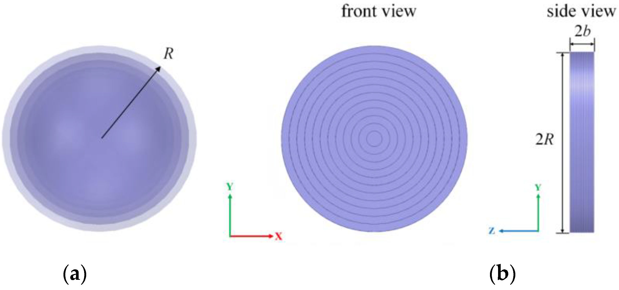
The design of an FLL can follow the transformation optics as described in [20], where the permittivity and permeability tensors, i.e., ε = and μ = , are firstly computed following the transformation of structures, i.e., transforming from a spherical Luneburg lens into a flat one, as shown in Figure 2. Note that the original spherical LL shown in Figure 2a has a radius as R, and its corresponding cylindrical FLL shown in Figure 2b has the same radius as R and a thickness as 2 × b. Hence, the constitution parameters for the FLL can be calculated as
ε = = ε Λ = Λ = T | Λ = |
μ = = μ Λ = Λ = T | Λ = |
where Λ is a Jacobian matrix defined by the transformation in a cylindrical coordinate (ρ, φ, z) to match up the radially rotational symmetry of either a conventional LL or an FLL with its axis along z-direction, as
Λ = = [ 1 0 0 0 1 0 z ρ R 2 ρ 2 0 b R 2 ρ 2 ]
Hence, both ε = and μ = are nondiagonal matrixes, which indicates that anisotropic materials should be adopted for the transformed FLL. This is relatively complex for engineering implementation. Hence, an approximation is applied to convert the obtained anisotropic FLL into an isotropic one to simplify the implementation, by both substituting the permittivity tensor for its component ερρ and replacing the permeability tensor with μr = 1. In this case, the FLL can be implemented by using isotropic materials with gradient index distribution.
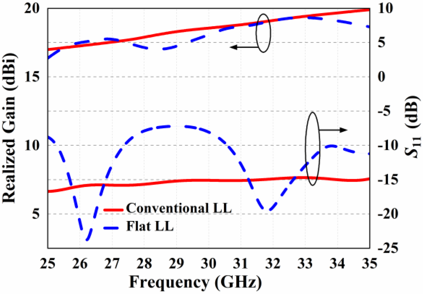
As pointed out in [20,22], the approximation would increase the focal length and deteriorate lens scanning performance. To further understand the degeneration of gain and bandwidth performance, a comparison was made between the conventional LL and its transformed FLL at the Ka-band using a simulation. The radius of the Luneburg sphere was set as R = 15 mm, and it was constructed with 12 equal-thickness-layer concentric spherical shells, as shown in Figure 2a. The corresponding flat lens has the same radius and a thickness as 2 × b = 5 mm, and it was decomposed into 12 equal-thickness layers along either the axis (longitudinal direction) or radius of the cylinder, as shown in Figure 2b. A compression rate of R/b = 6 was adopted for the FLL design, and the dominate range of the transformed permittivity was enlarged from the original [1,2] to [6,12], multiplied by the compression ratio. Each layer of both two lenses were modeled with perfect dielectrics whose permittivities are specified with the desired value, and the dielectric loss was omitted during simulation.
Both the two LLs were excited with a WR28 open-ended waveguide over 25–35 GHz, and Figure 3 shows the simulated S11 and realized gain of two lenses. It was observed that the FLL exhibits a narrower bandwidth in terms of both S11 < −10 dB and gain flatness, although at the two resonance frequencies of 26.2 GHz and 31.8 GHz, a compatible performance was achieved for the FLL, comparing with that of the conventional LL. Besides the two frequencies, the gain curve of FLL was lower than that of the conventional LL, and the largest discrepancy was around 2.5 dB. Figure 4 shows the simulated radiation patterns of both lenses at 30 GHz, where the gain of the FLL is 18.1 dBi and that of the conventional LL is 18.6 dBi. The back lobe of the FLL is evidently larger than that of the conventional LL, because the used isotropic approximation and the high permittivity (or the neglect of permeability) cause a mismatch at the surfaces between the FLL and the air, resulting in an evident reflection. It was proven that the reflection can produce −10 dB backside radiation in [20], which degrades the gain and efficiency of the FLL.

3. Flat Luneburg Design and Implementation

3.1. Flat Luneburg Lens

The implementation of the FLL used a multilayer PCB structure similar to the metamaterial method proposed in [20]. Considering that the desired thickness of the FLL is 5 mm and the operating frequency is over 25–35 GHz, the substrate of Rogers 4003C (εr = 3.38, tanδ = 0.0027) with a thickness of 0.305 mm was chosen. The used unit cell in each layer was a square patch on a square substrate, and the size of the unit cell is 1.6 mm × 1.6 mm, as shown in Figure 5a. The patch is located at the interface between the substrate and air, and the adjacent substrate layers are separated with a fixed air interval. The function of the air interval is discussed later. It is noteworthy that the used unit cell is different from that in [20], where the patch is sandwiched by two substrate layers without any air interval. By tuning the size of the patch, its effective permittivity varies from 3.38 to 13 with good consistency over the bandwidth of 27–31 GHz, as illustrated in Figure 5a.
The FLL is composed of 10-layer substrates, and each layer comprises 20 × 20 unit-cells, as shown in Figure 5b. The total size of the FLL is 32 mm × 32 mm × 5.75 mm. A circular area with a diameter of 16 mm represents the effective FLL area, filling the unit cells with the proposed unit-cells of patches, and the rest of the peripheral substrates are drilled with a uniform air hole array of 1.6 mm × 1.6 mm pixels to suppress the propagation of surface waves in a millimeter-wave band. The detailed patch size of each unit cell was determined according to the curve shown in Figure 5a with a projection subject to its localized permittivity, which is calculated using Equation (1). Hence, a radial variation can be seen in Figure 5b.

3.2. Feeding Patch Antenna

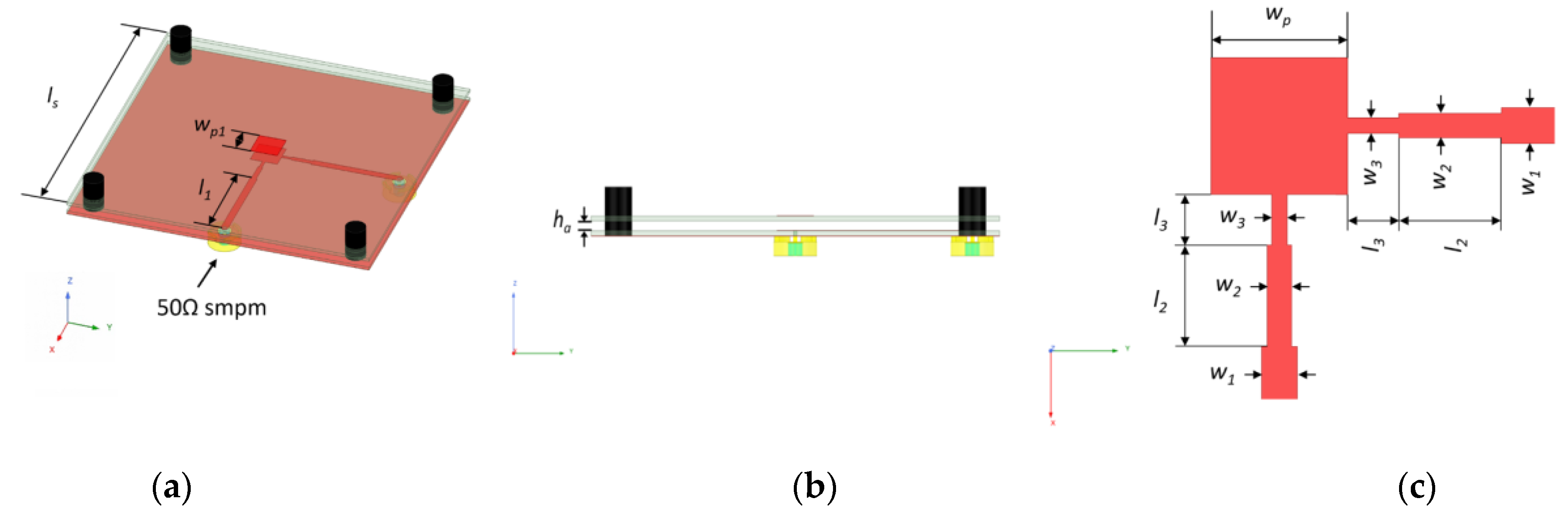
To accomplish dual-polarized performance, a dual-polarized stacked microstrip patch antenna was used as the feeding source for the FLL, as shown in Figure 6. The used two substrate layers are both Rogers 4003C (εr = 3.38, tanδ = 0.0027). The bottom patch is directly excited by two SMPM connectors using two orthogonally displaced tri-section stepped-impedance-microstrip-line transformers for dual polarizations, and the top patch is on the bottom of the superstrate. The antenna was designed at the targeted frequency band, and its performance is shown later.

3.3. Reflection Cancellation Method

In this design, an air interval is introduced between adjacent layers in the FLL, which has three functions: (1) it can reduce the strong coupling between adjacent patches, which cannot be modeled during the retrieval of effective permittivity with only one layer unit cell, as shown in Figure 5a; (2) by tuning the air gap, the operating frequency and bandwidth can be adjusted to one that functions in the design of the frequency-selective surface (FSS) [23]; (3) the air gap can provide a reflection cancellation phenomenon, which can enhance the performance of the FLL in terms of gain and bandwidth.
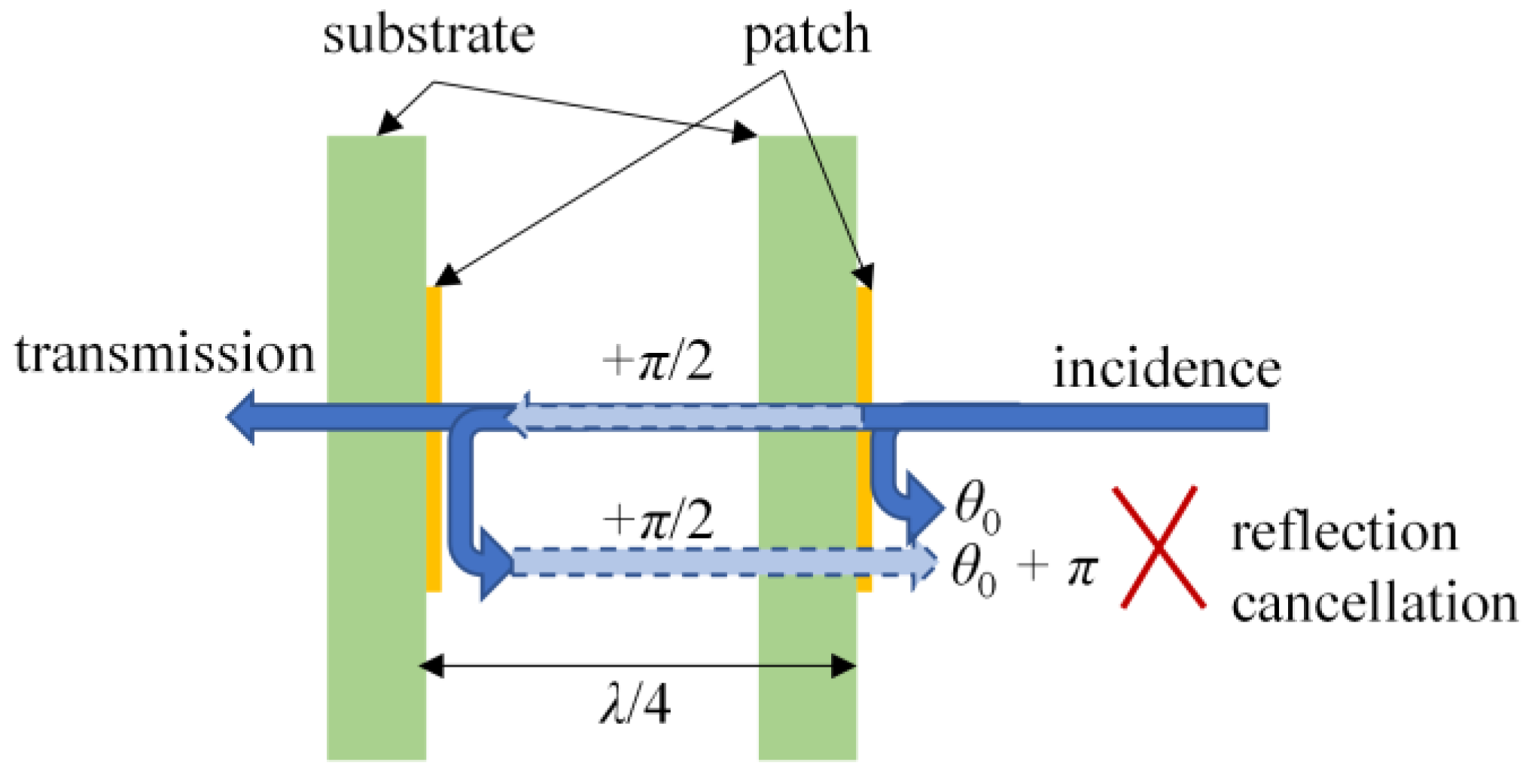
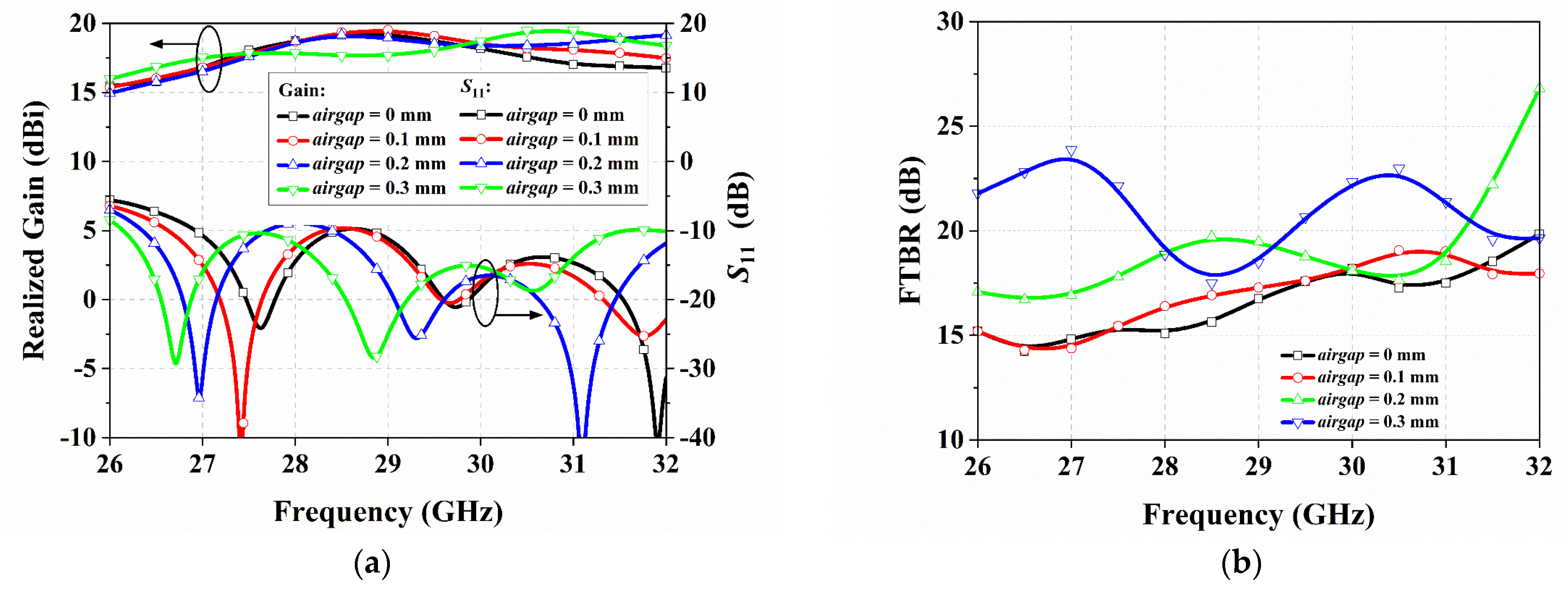
To illustrate the operating scheme of the reflection cancellation, an illustrated diagram is shown in Figure 7. Suppose that the two layers are separated with a distance equal to a quarter of the wavelength, i.e., λ/4, the reflections occurring at the two interfaces on the same side of the two layers would be superposed with a phase difference of π, resulting a reflection cancellation. Therefore, the air interval between adjacent layers provides additional design freedom to optimize the performance of the FLL. Note that the two-layer model shown in Figure 7 is frequency-dependent, but the real case in an FLL with multilayers is more complicated than in the two-layer model. In the FLL, there are multiple reflections occurring at each layer and mutual couplings among layers, all of which contribute to wideband performance. Hence, a parameter study was carried out by varying the thickness of the air interval, noted as the airgap, to investigate its influence on S11, gain, and FTBR simultaneously, as shown in Figure 8. Note that the air interval between any two adjacent layers was set identically to simplify both the optimization and implementation. The parameter study does not only result in a simple way of changing the air interval, as the FLL should also be re-designed with the revised air interval each time. This is because the variation in airgap will change the total thickness of the FLL, resulting in a revised comparison R/b ratio. Meanwhile, the location of each layer varies with the changing in the air interval as well. Thus, the permittivity should be recomputed and discretized for the design of the unit cell at any specified airgap. Thanks to a script-based modelling method in Ansys HFSS, the parameter study can be executed in an automatic way.
As can be seen in Figure 8a, with the increasing in airgap, the resonances on the S11 curves shifted to low frequency as assumed. A good bandwidth of 26.1–31.6 GHz in terms of S11 < −10 dB was achieved when the airgap was 0.3 mm, and the gain curve exhibited good flatness as well. The FTBR exhibited similar trends in that it achieved its largest value when the airgap is 0.3 mm, as shown in Figure 8b. Hence, airgap = 0.3 mm was chosen for the design of the FLL, and it derived a final designed FLL with a total thickness of 5.75 mm. Though airgap = 0.01 mm corresponds to a wide band in terms of S11 < −10 dB, the gain has a large variation over the bandwidth, which mainly attributes to the strong reflection of the FLL.

3.4. Dual-Polarized FLLA

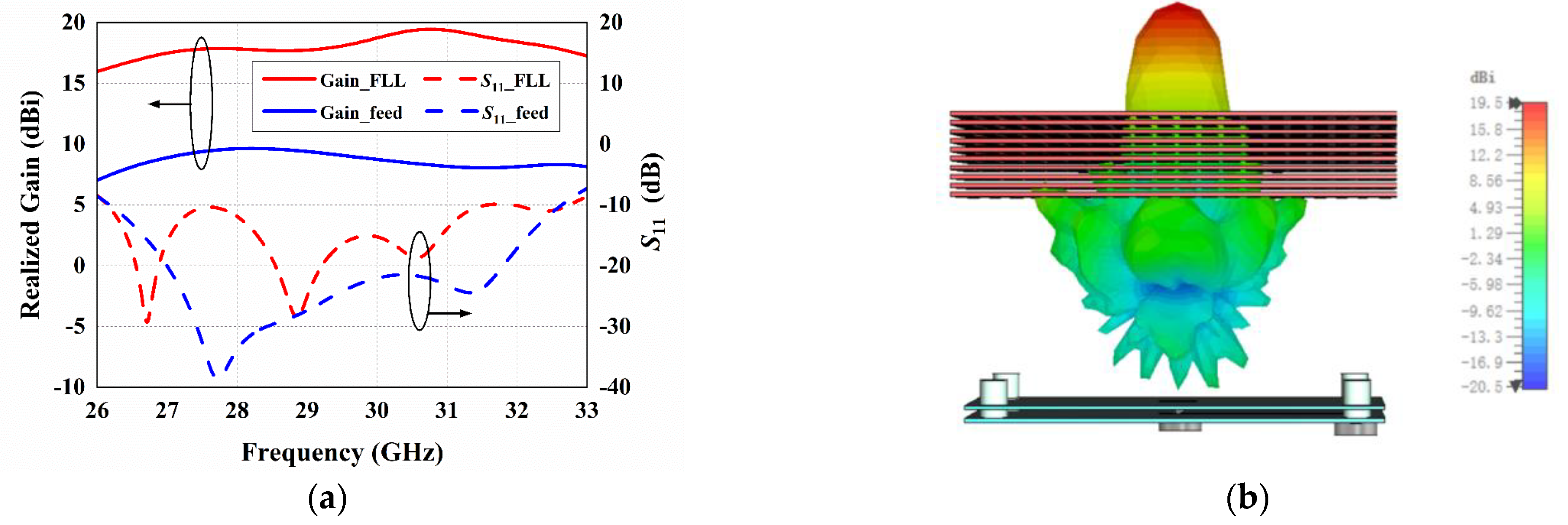
The designed FLL was excited with the dual-polarized stacked microstrip patch antenna, and its simulated results are shown in Figure 9 and Figure 10. Since the two ports of the feeding antenna are symmetrical to each other, only the results corresponding to port-1 are provided for brevity. Figure 9 shows the simulated S11 and gain of the FLLA comparing with the counterparts of its feed only. It can be seen that although the S11 of the FLLA shifted up, it was still smaller than −10 dB, achieving a bandwidth of 26.1–32.6 GHz, similar to that of the feeding stacked patch antenna. Meanwhile, the gain of FLLA significantly improved comparing to that of feed only, and it varied within 16.5–19.5 dBi over the impedance bandwidth. Figure 10 provides the simulated radiation patterns on either the E- or H-plane of the FLLA under excitation of port-1 (results of port-2 are omitted for brevity), at 27, 29, and 31 GHz, respectively, which compare with those of feed only as well. The FLL concentrated the electromagnetic waves radiated by the feeding antenna into a narrow beam in both E- and H-planes, proving its 2D focusing ability. The 3 dB beam-widths in the E- and H-plane were around 16.5° and 16.2°, respectively. The cross-polarization levels were −18.5 dB in the main lobe over the bandwidth. Meanwhile, the FTBRs were greater than 19.5 dB at all three frequencies, certifying that the reflection caused by the FLL was successfully suppressed.
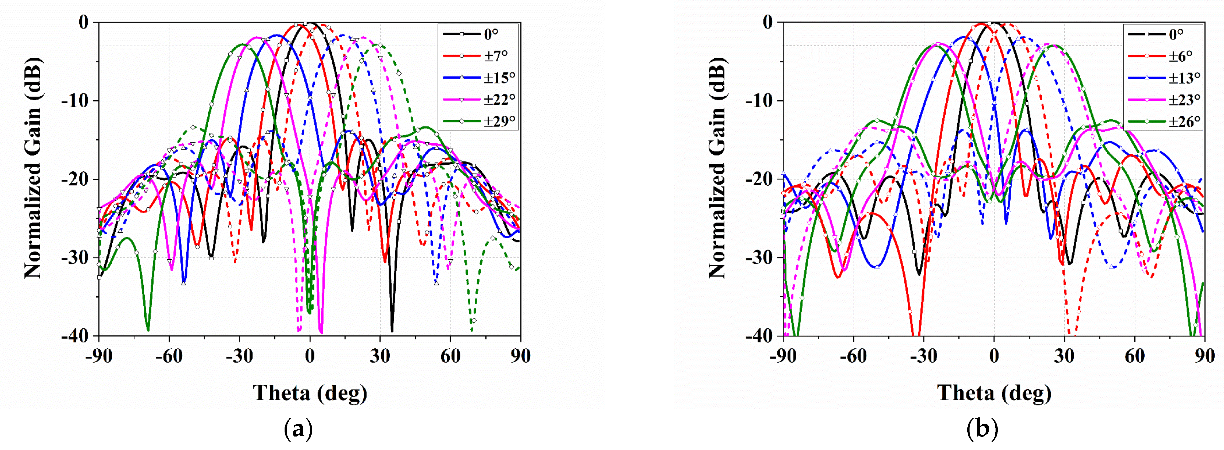
Furthermore, to demonstrate the beam scanning ability of the designed FLLA, the FLL was excited by moving the feeding patch antenna in the transverse plane either vertically or horizontally. Without loss of generality, the scanned beams in the E- and H-planes when port-1 is excited were simulated, as shown in Figure 11. The steering angles in the E-plane were 0°, ±7°, ±15°, ±22°, and ±29°, corresponding to the feeding antenna’s shifts of 0, 0.35, 0.7, 1.05, 1.2 mm in the E-plane, respectively. The steering angles in the H-plane were 0°, ±6°, ±13°, ±23°, and ±26°, corresponding to the feeding antenna’s shifts of 0, 0.35, 0.7, 1.05, 1.4 mm in the E-plane, respectively. The largest scanning angle in either E- or H-plane was determined using a criterion of 3 dB gain loss.

4. Implementation, Measurements and Discussions

4.1. Implementation of FLLA

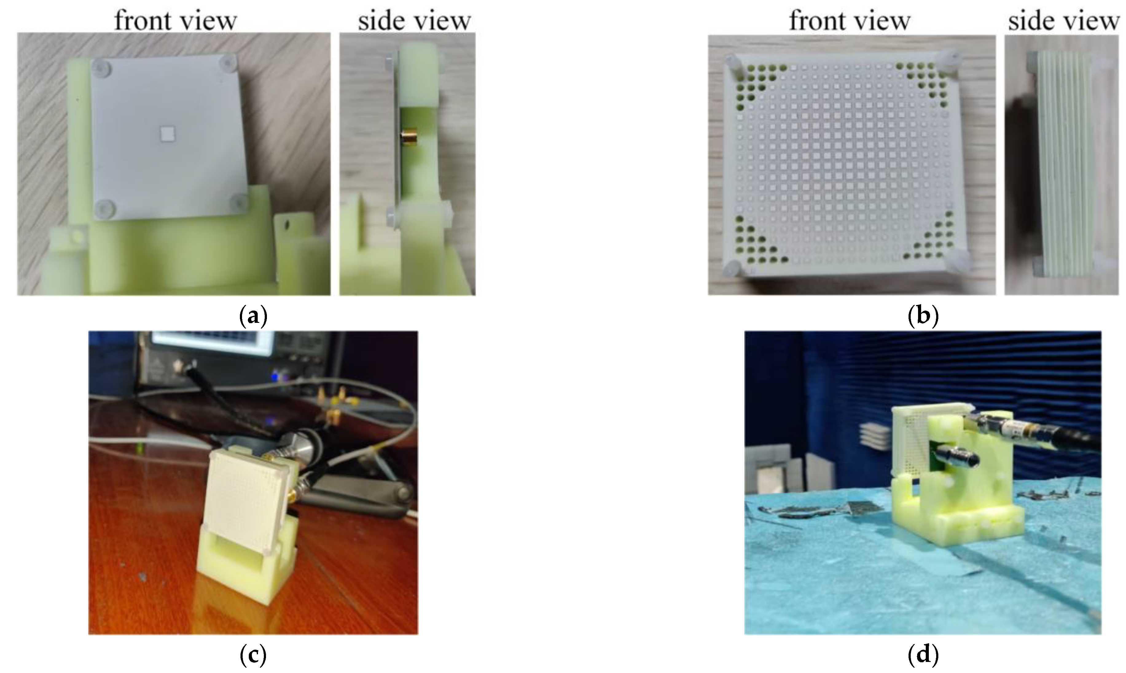
The designed FLLA was fabricated using a standard PCB process and the used substrate was a Rogers RO4003C. A postprocessing was introduced to install both the feeding stacked patch antenna and the FLL using a 3D-printed supporter, as shown in Figure 12. The feeding antenna was assembled with four nylon screws to be mounted with a slidable supporter, allowing it to move in the transverse plane for beam scanning purposes. The fabricated 10-layer PCB boards were assembled using nylon screws as well to compose the FLL, and later mounted onto the same supporter.

4.2. Measurement of FLLA

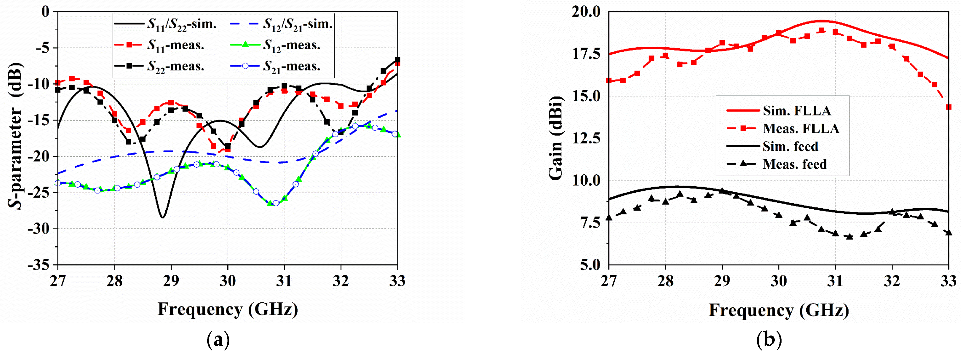
The fabricated prototype was measured to characterize its performance following a standard procedure. A vector network analyzer (VNA), Keysight N5225B (10 MHz–50 GHz), was used to measure the S-parameter. The measured S-parameter of the FLLA is shown in Figure 13a. It can be seen that the measured common impedance bandwidth for two ports is 27.5–32.6 GHz in terms of both S11 < −10 dB and S22 < −10 dB, and the measured couplings between two ports are smaller than −16 dB over the bandwidth. The measured curves are in accordance with the simulations in trends, and a small frequency shifting is observed on S11/S22 curves.
The far-field radiation patterns of the fabricated FLLA were measured in a far-field anechoic chamber (0.5–110 GHz) in Southeast University. The measured gain of both the FLLA and the feeding stacked patch antenna is shown in Figure 13b. The measured gain curves exhibit a reasonable agreement with the simulations. The FLLA achieved a measured gain of 16.55–18.88 dBi for port-1 and 16.5–18.67 dBi for port-2 over the impedance bandwidth, comparing with the measured gain of 6.4–8.9 dBi for the feeding antenna. The slight difference between the gain of port-1 and port-2 is assumed to be affected by the used supporter.
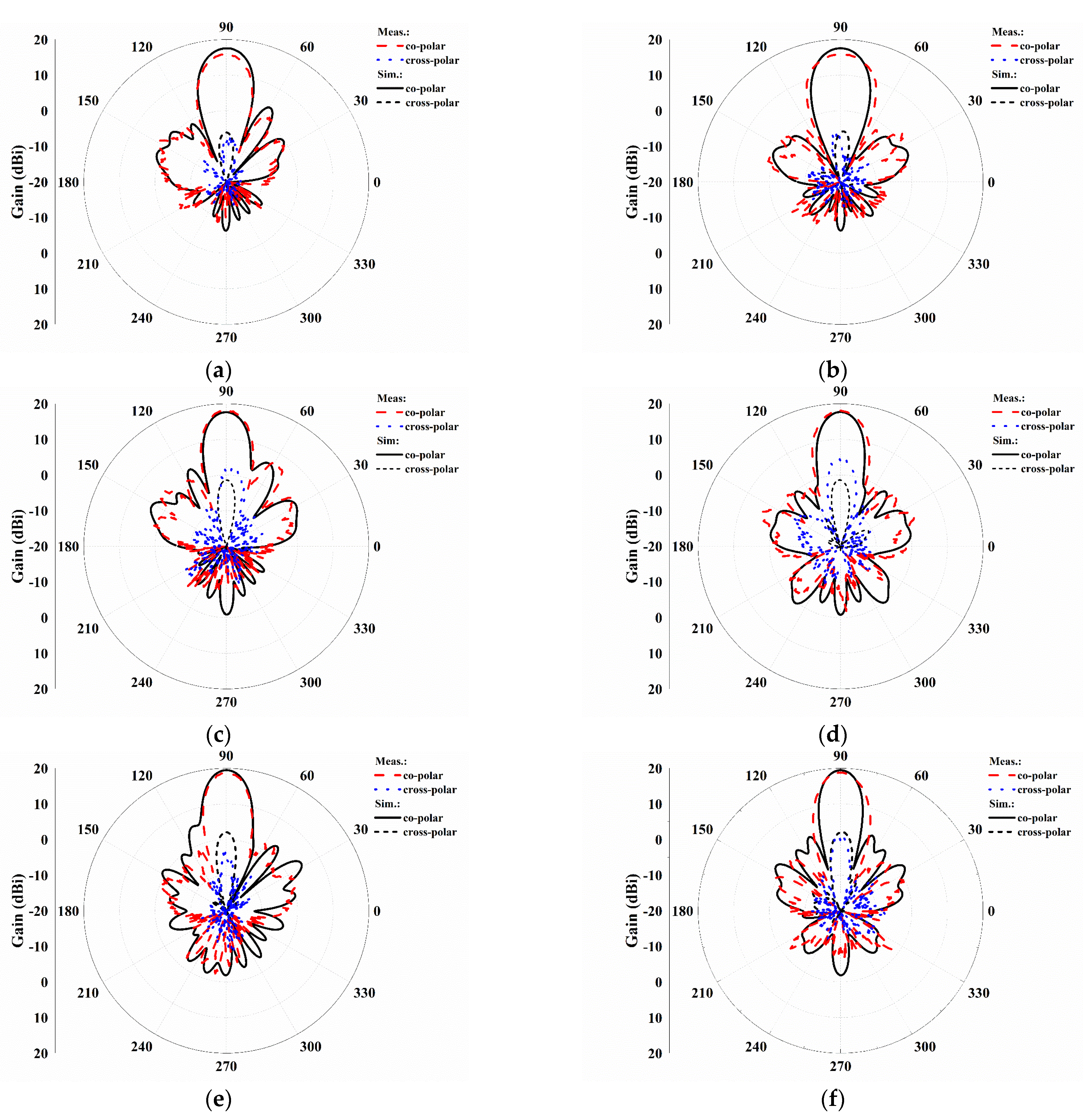
Without loss of generality, the measured radiation patterns of the FLLA excited by port-1 were compared with simulations at 27, 29, and 31 GHz, respectively, as shown in Figure 14, which show good agreements. The measured 3 dB beam-widths in the E- and H-planes were 17° and 16.5°, respectively. The measured side lobe levels (SLLs) were smaller than −13 dB in the E-plane and −15 dB in the H-plane. The cross-polarization levels were −19 dB in the main lobe for 27 and 31 GHz, while that for 29 GHz degenerated to −15 dB. Meanwhile, the FTBRs were greater than 19.5 dB at all three frequencies, demonstrating that a desired small reflection was achieved.
Without loss of generality, the scanned beams in the E- and H-plane when port-1 is excited were measured, as shown in Figure 15. The measured steering angles in E-plane were 0°, ±7°, ±17°, ±22°, and ±25°, corresponding to the feeding antenna’s shifts of 0, 0.35, 0.7, 1.05, 1.2 mm in the E-plane, respectively. The steering angles in the H-plane were 0°, ±6°, ±15°, ±19°, and ±24°, corresponding to the feeding antenna’s shifts of 0, 0.35, 0.7, 1.05, 1.4 mm in the E-plane, respectively. In the measured scanning angle ranges, the gain loss in either the E- or H-plane was smaller than 1.72 dB or 1.7 dB, respectively.
The measured scanning beams exhibited narrow angle ranges and smaller gain loss than those of simulations. The reason is that the actual shifts in the feeding antenna cannot be accurately controlled as desired at a millimeter scale, which would involve an error to the steering angles. Meanwhile, the used supporter was backed to the feeding patch antenna, prohibiting the backward movement of the feeding antenna. But this cannot ensure that the feeding antenna moves exactly in the transvers plane. If a forward movement is happened during the transverse moving and the feeding patch antenna is closer to the FLL in turn, the gain will be increased for the oblique radiated beams. As demonstrated in [20], the focal plane of the FLL is not a planar one, but a curvature one for which a shorter focal length is required for a larger shift in the feeding source.

4.3. Discussion

The achieved performance of the FLLA was compared with the conventional spherical LL (discussed in Section 2) and other related works, as illustrated in Table 1. The spherical LL is used as a benchmark because its performance is the best except for its gain, because the used 12-layer structure is divided with a criterion of equal space but not equal permittivity step. The FLL in [13] is a type of horizontally placed cylindrical FLL, as shown in Figure 1c, and a metal grid is applied on its both top and bottom interfaces to improve its sidelobe level performance. Thus, the FLL in [13] cannot be operated with dual polarizations or 2D beam scanning. Our work exhibited better performance in terms of gain and aperture efficiency than the design reported in [20,21] due to the introduced reflection cancellation method. Moreover, the presented work is demonstrated in millimeter wave band. Hence, the smaller wavelength limits the adopted layers in our design, i.e., 10 layers, which is smaller than those used in [20,21]. Thus, the achieved impedance bandwidth is a little bit narrower as well. Actually, an X-band prototype was implemented following the method proposed in this article, and a 30% bandwidth was achieved due to the introduced reflection cancellation method, which is not reported here.
In our design, all the air intervals in-between any two adjacent layers of the FLL were set to be identical for simplicity. If all the air intervals can be independently tuned, a better performance is expected.

5. Conclusions

In this paper, the design of a flat Luneburg lens was proposed by introducing the reflection cancellation method. A dual-polarized FLL was designed and prototyped at the Ka-band, and it was demonstrated that the proposed design method can effectively enhance gain and aperture efficiency and suppress backside radiation.
The proposed design is promising for multibeam antenna systems in 5G and beyond applications. For instance, the designed FLLA can be adopted in customer premise equipment in small cells to support multiple beams simultaneously, resulting in multiplied system capacity. As stated in the Discussion section, since the operating frequency band was chosen at the Ka-band, the number of adopted layers for the FLL is limited to 10 due to the small operating wavelength and available PCB substrates. If a thinner PCB substrate can be used to design the target FLL with more layers, the bandwidth is expected to be much wider. This will be explored in future work.

Author Contributions

Conceptualization, Y.Z.; methodology, Y.Z. and Y.L.; experiments and data curation, Y.L. and R.J.; writing—review and editing, Y.Z. All authors have read and agreed to the published version of the manuscript.

Funding

This research received no external funding.

Institutional Review Board Statement

Not applicable.

Informed Consent Statement

Not applicable.

Data Availability Statement

Not applicable. All the design parameters are provided within this artical.

Acknowledgments

The authors are grateful to Tianyi Huo of State Key Laboratory of Millimeter Waves for his help in the measurements.

Conflicts of Interest

The authors declare no conflict of interest.

References

  1. Hong, W.; Jiang, Z.H.; Yu, C.; Zhou, J.; Chen, P.; Yu, Z.; Zhang, H.; Yang, B.; Pang, X.; Jiang, M.; et al. Multibeam antenna technologies for 5G wireless communications. IEEE Trans. Antennas Propag. 2017, 65, 6231–6249. [Google Scholar] [CrossRef]
  2. Hemadeh, I.A.; Satyanarayana, K.; El-Hajjar, M.; Hanzo, L. Millimeter-wave communications: Physical channel models design considerations antenna constructions and link-budget. IEEE Commun. Surv. Tuts. 2018, 20, 870–913. [Google Scholar] [CrossRef]
  3. Osseiran, A.; Boccardi, F.; Braun, V.; Kusume, K.; Marsch, P.; Maternia, M.; Queseth, O.; Schellmann, M.; Schotten, H.; Taoka, H.; et al. Scenarios for 5G mobile and wireless communications: The vision of the METIS project. IEEE Commun. Mag. 2014, 52, 26–35. [Google Scholar] [CrossRef]
  4. He, S.; Zhang, Y.; Wang, J.; Zhang, J.; Ren, J.; Zhang, Y.; Zhuang, W.; Shen, X. A survey of millimeter-wave communication: Physical-layer technology specifications and enabling transmission technologies. Proc. IEEE 2021, 109, 1666–1705. [Google Scholar] [CrossRef]
  5. Mosallaei, H.; Rahmat-Samii, Y. Non-uniform Luneburg and two shell lens antennas: Radiation characteristics and design optimization. IEEE Trans. Antennas Propag. 2001, 49, 60–69. [Google Scholar] [CrossRef]
  6. Yang, J.; Li, N.; Ma, P.; Liu, B. Calibration of Radar RCS Measurement Errors by Observing the Luneburg Lens Onboard the LEO Satellite. Sensors 2022, 22, 5421. [Google Scholar] [CrossRef]
  7. Liang, M.; Ng, W.R.; Chang, K.; Gbele, K.; Gehm, M.E.; Xin, H. A 3-D Luneburg lens antenna fabricated by polymer jetting rapid prototyping. IEEE Trans. Antennas Propag. 2014, 62, 1799–1807. [Google Scholar] [CrossRef]
  8. Sayanskiy, A.; Glybovski, S.; Akimov, V.P.; Filonov, D.; Belov, P.; Meshkovskiy, I. Broadband 3-D Luneburg lenses based on metamaterials of radially diverging dielectric rods. IEEE Antenna Wirel. Propag. Lett. 2017, 16, 1520–1523. [Google Scholar] [CrossRef]
  9. Fuchs, B.; Coq, L.L.; Lafond, O.; Rondineau, S.; Himdi, M. Design optimization of multi-shell Luneburg lenses. IEEE Trans. Antennas Propag. 2007, 55, 283–289. [Google Scholar] [CrossRef]
  10. Lian, J.-W.; Ansari, M.; Hu, P.; Guo, Y.J.; Ding, D. Wideband and high-efficiency parallel-plate Luneburg lens employing all-metal metamaterial for multibeam antenna applications. IEEE Trans. Antennas Propag. 2023, 71, 3193–3203. [Google Scholar] [CrossRef]
  11. Lu, H.; Liu, Z.; Liu, Y.; Ni, H.; Lv, X. Compact air-filled Luneburg lens antennas based on almost-parallel plate waveguide loaded with equal-sized metallic posts. IEEE Trans. Antennas Propag. 2019, 67, 6829–6838. [Google Scholar] [CrossRef]
  12. Hu, B.; Wu, T.; Cai, Y.; Zhang, W.; Zhang, B. A novel metamaterial-based planar integrated Luneburg lens antenna with wide bandwidth and high gain. IEEE Access 2020, 8, 4708–4713. [Google Scholar] [CrossRef]
  13. Liu, P.; Zhu, X.-W.; Zhang, Y.; Jiang, Z.H.; Wang, X.; Hong, W.; Le, T.H. A novel E-plane-focused cylindrical Luneburg lens loaded with metal grids for sidelobe level reduction. IEEE Trans. Antennas Propag. 2020, 68, 736–744. [Google Scholar] [CrossRef]
  14. Luo, Y.; Ji, R.; Zhang, Y. Performance analysis of planar Luneburg lens and full dielectric lens. In Proceedings of the 2022 IEEE 10th Asia-Pacific Conference on Antennas and Propagation (APCAP), Xiamen, China, 14–16 November 2022. [Google Scholar]
  15. Quevedo-Teruel, O.; Tang, W.; Hao, Y. Isotropic and nondispersive planar fed Lüneburg lens from Hamiltonian transformation optics. Opt. Lett. 2012, 37, 4850–4852. [Google Scholar] [CrossRef]
  16. Wu, L.; Tian, X.; Ma, H.; Yin, M.; Li, D. Broadband flattened Lüneburg lens with ultra-wide angle based on a liquid medium. Appl. Phys. Lett. 2013, 102, 074103. [Google Scholar] [CrossRef]
  17. Wan, X.; Jiang, W.X.; Ma, H.F.; Cui, T.J. A broadband transformation-optics metasurface lens. Appl. Phys. Lett. 2014, 104, 151601. [Google Scholar] [CrossRef]
  18. Ma, H.F.; Cui, T.J. Three-dimensional broadband and broad angle transformation-optics lens. Nat. Commun. 2010, 1, 124. [Google Scholar] [CrossRef]
  19. Mateo-Segura, C.; Dyke, A.; Dyke, H.; Haq, S.; Hao, Y. Flat Lüneburg lens via transformation optics for directive antenna applications. IEEE Trans. Antennas Propag. 2014, 62, 1945–1953. [Google Scholar] [CrossRef]
  20. Su, Y.; Chen, Z.N. A flat dual-polarized transformation-optics beamscanning Luneburg lens antenna using PCB-stacked gradient index metamaterials. IEEE Trans. Antennas Propag. 2018, 66, 5088–5097. [Google Scholar] [CrossRef]
  21. Su, Y.; Chen, Z.N. A radial transformation-optics mapping for flat ultra-wide-angle dual-polarized stacked GRIN MTM Luneburg lens antenna. IEEE Trans. Antennas Propag. 2019, 67, 2961–2970. [Google Scholar] [CrossRef]
  22. Xu, R.; Chen, Z.N. A transformation-optics-based flat metamaterial Luneburg lens antenna with zero focal length. IEEE Trans. Antennas Propag. 2022, 70, 3287–3296. [Google Scholar] [CrossRef]
  23. Munk, B. Finit Antenna Arrays and FSS; Wiley-IEEE: Hoboken, NJ, USA, 2003. [Google Scholar]
Figure 1. Various Luneburg lenses: (a) conventional LL, (b) layered LL with concentric spherical shells, (c) horizontally placed cylindrical flat LL, (d) vertically placed cylindrical flat LL.
Applsci 13 06468 g001
Figure 2. Luneburg lens: (a) conventional spherical LL, (b) transformed FLL.
Applsci 13 06468 g002
Figure 3. Comparison between conventional LL and FLL: simulated S11 and realized gain.
Applsci 13 06468 g003
Figure 4. Simulated three-dimensional radiation patterns: (a) conventional LL, (b) FLL.
Applsci 13 06468 g004
Figure 5. Implementation of FLL: (a) unit-cell and its equivalent permittivity, (b) implemented FLL. (h = 0.305 mm, a = 1.6 mm).
Applsci 13 06468 g005
Figure 6. Dual-polarized microstrip patch antenna: (a) perspective view, (b) side view, (c) patch and feeding microstrip line. (ls = 30, w1 = 0.7, l1 = 9, w2 = 0.48, l2 = 2, w3 = 0.3, l3 = 1, wp1 = wp2 = 2.7, ha = 0.6, all in millimeters).
Applsci 13 06468 g006
Figure 7. Illustration of reflection cancellation phenomenon in a two-layer structure.
Applsci 13 06468 g007
Figure 8. Investigation of air interval in-between substrate layers of FLL performance: (a) S11 and gain, (b) FTBR.
Applsci 13 06468 g008
Figure 9. Simulated results of the FLLA: (a) S11 and gain, comparing with those of feed only, (b) model with 3D radiation pattern.
Applsci 13 06468 g009
Figure 10. Simulated radiation patterns of the FLLA: (a) E-plane at 27 GHz, (b) H-plane at 27 GHz, (c) E-plane at 29 GHz, (d) H-plane at 29 GHz, (e) E-plane at 31 GHz, (f) H-plane at 31 GHz.
Applsci 13 06468 g010aApplsci 13 06468 g010b
Figure 11. Simulated scanning beams of FLLA: (a) E-plane, (b) H-plane.
Applsci 13 06468 g011
Figure 12. Photos of prototypes: (a) feeding stacked patch antenna; (b) FLL; (c) entire FLLA; (d) measuring in anechoic chamber.
Applsci 13 06468 g012
Figure 13. Measured S-parameter and gain of prototypes: (a) S-parameter for FLLA; (b) gain for FLLA and feeding patch antenna.
Applsci 13 06468 g013
Figure 14. Simulated and measured radiation patterns of the FLLA: (a) E-plane at 27 GHz, (b) H-plane at 27 GHz, (c) E-plane at 29 GHz, (d) H-plane at 29 GHz, (e) E-plane at 31 GHz, (f) H-plane at 31 GHz.
Applsci 13 06468 g014
Figure 15. Measured scanning beams of FLLA: (a) E-plane, (b) H-plane.
Applsci 13 06468 g015
Table 1. Performance comparisons between designed FLLA, conventional LL, and other related works.
PerformanceSpherical LL #
(in This Work)
FLL in [13] FLL in [20]FLL in [21]This Work
Operating freq.
(GHz)
2926101029
Electrical size
(λ at central freq.)
(4π/3) × 293π × (3.82)2 × 1.733.29 × 3.29 × 0.473.14 × 3.14 × 0.53.1 × 3.1 × 0.56
Number of layers126171810
Fract. bandwidth>33%~17.3 ⁕21%20%17.6%
Comparison ratio
(R/b)
None2.26.876.285.56
Gain(dB)18.1 @ 31 GHz17.4 @ 26 GHz15.88/16.35
@10 GHz
13/13.2
@10 GHz
18.88/18.67
@ 30.8 GHz
Polarizationdual pol.single pol.dual pol.dual pol.dual pol.
Scanning angle
(gain loss)
2D full angle1D full angle±32° (~2.5 dB ⁕)/
±35° (~2 dB ⁕)
±54° (0.7 dB)/
±54° (2.2 dB)
±25° (1.72 dB)/
±24° (1.7 dB)
FTBR (dB)26~17.5 ⁕101019.5
X-pol. level (dB)−40−20−17−15−15
Aperture efficiency----46.2%21.2%81.7%
# Perfect dielectric is used without loss. ⁕ calculated using data in references.
Disclaimer/Publisher’s Note: The statements, opinions and data contained in all publications are solely those of the individual author(s) and contributor(s) and not of MDPI and/or the editor(s). MDPI and/or the editor(s) disclaim responsibility for any injury to people or property resulting from any ideas, methods, instructions or products referred to in the content.