
Vibration Attenuation in a High-Rise Hybrid-Timber Building: A Comparative Study


Abstract
1. Introduction
Timber-Based Hybridization
2. Wind and Earthquake Performance of Timber Buildings
2.1. Seismic Performance
2.2. Wind Performance
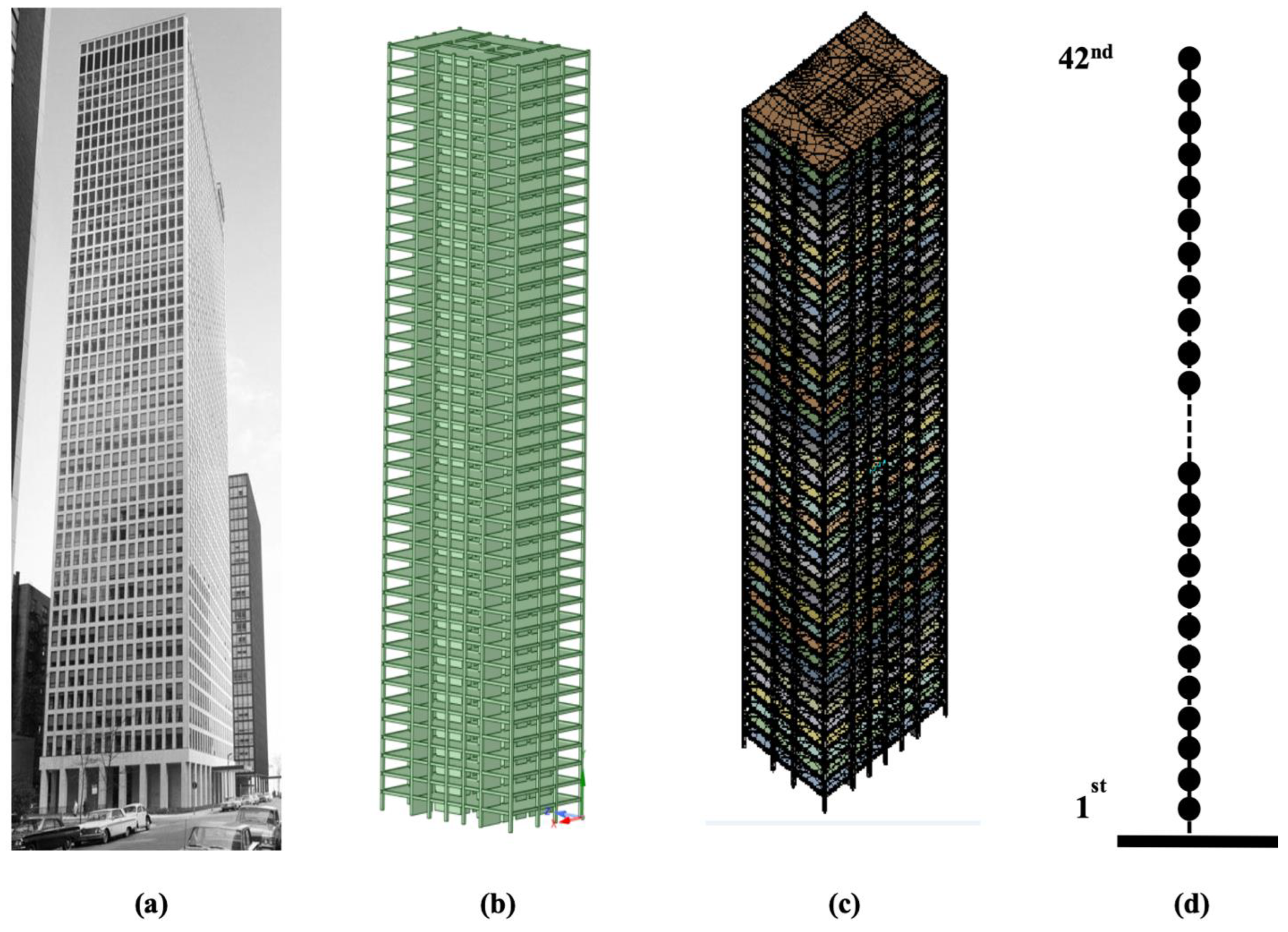
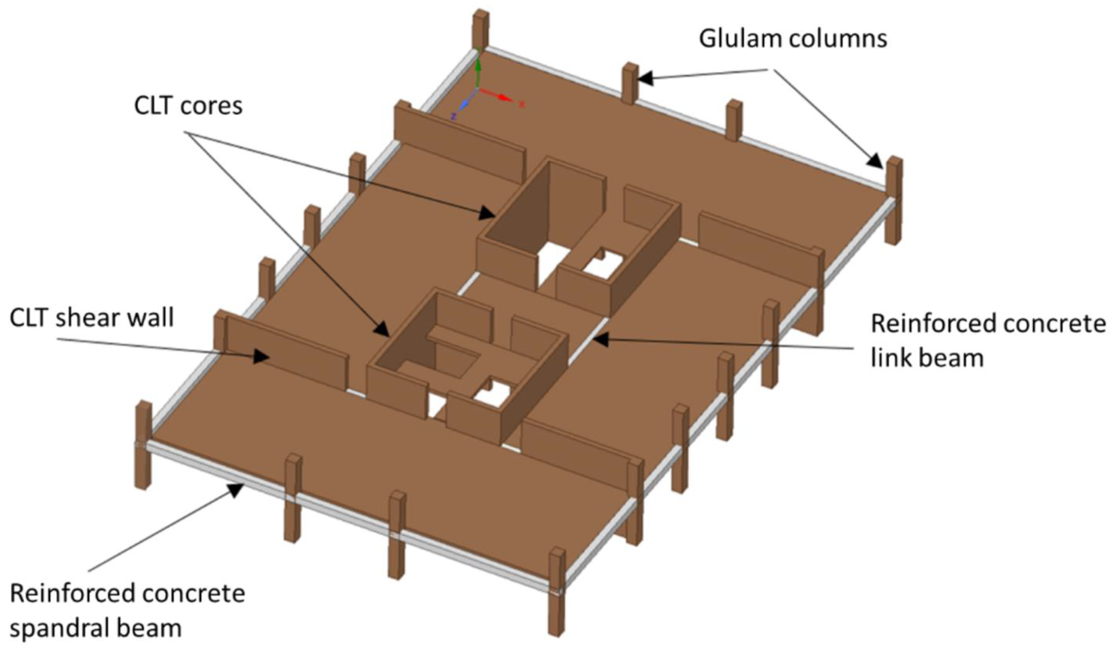
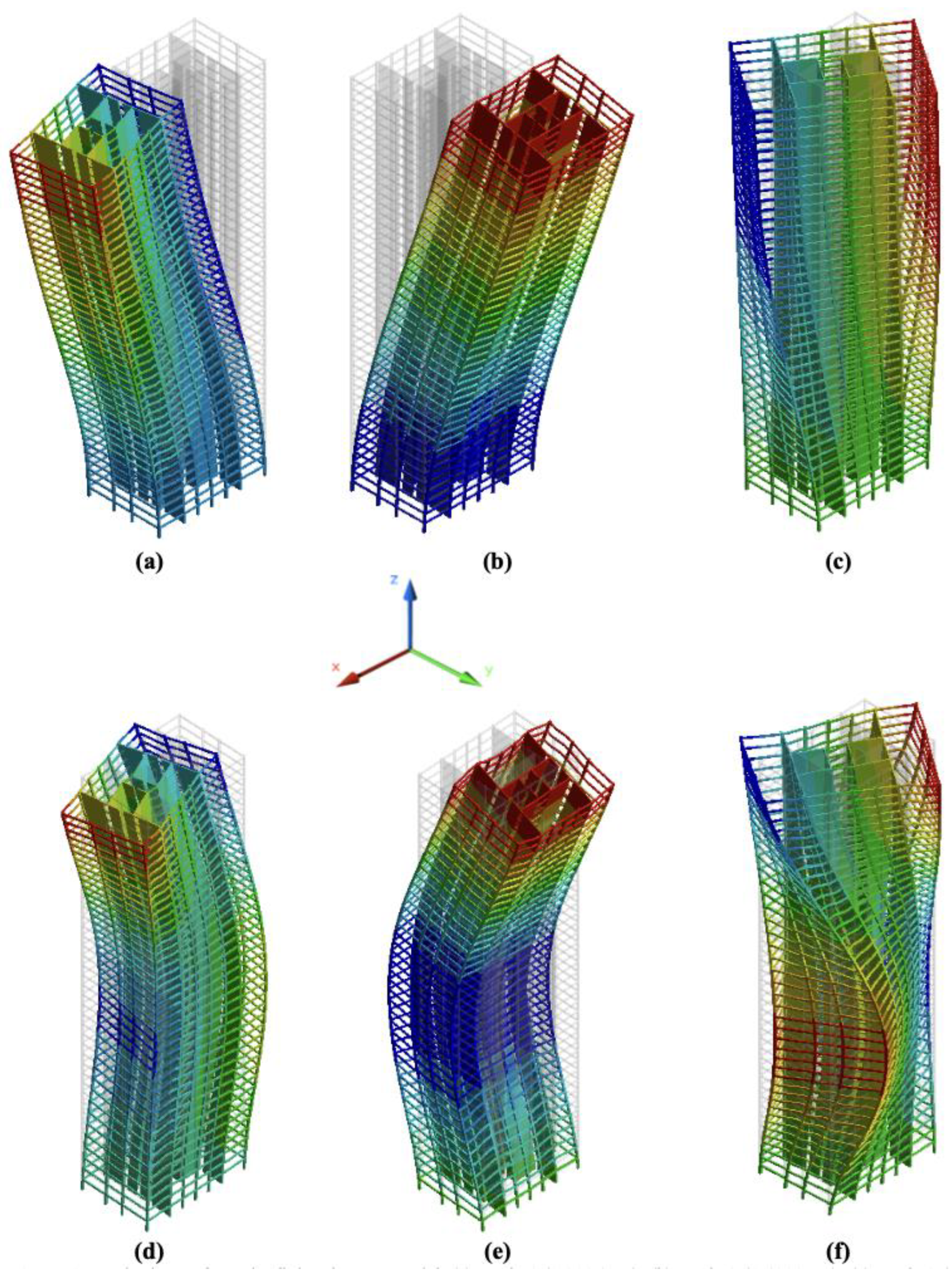
3. Case Study of a Mass Timber Building
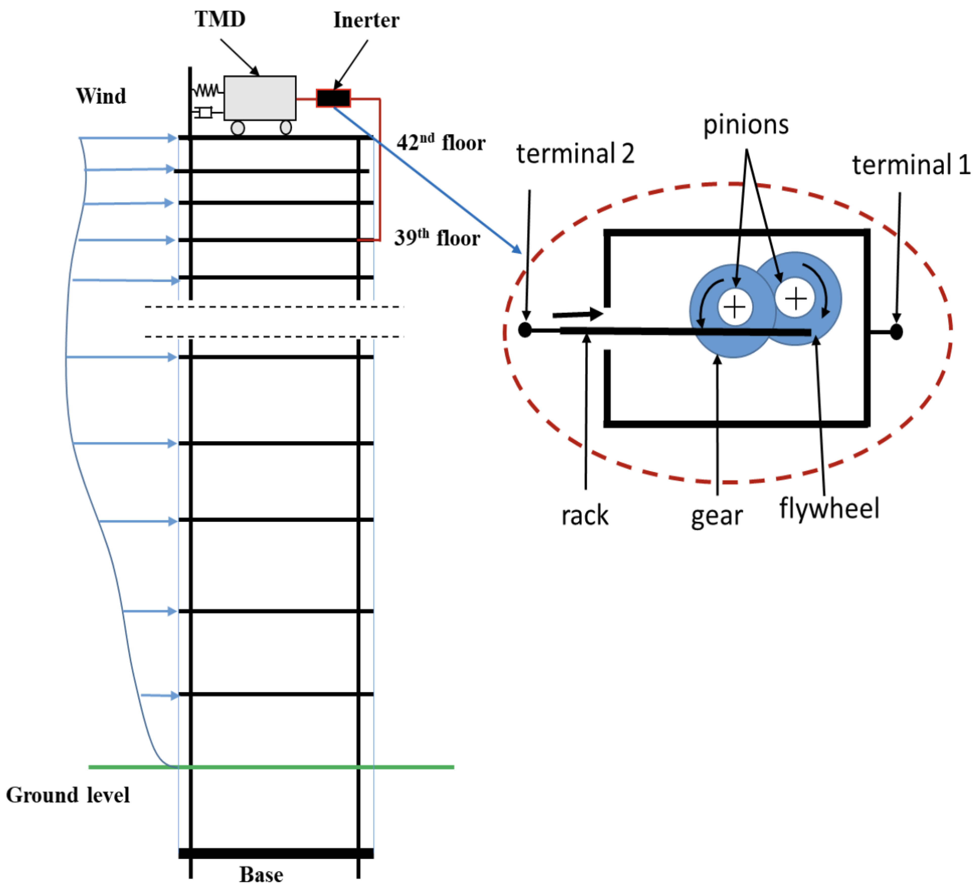
4. Tuned Mass Damper Inerter (TMDI) and the Equivalent TMD
4.1. Structural Control
4.2. Tuned Mass Damper Inerter (TMDI)
4.3. Equivalent TMD
5. Structural Modeling with TMDI
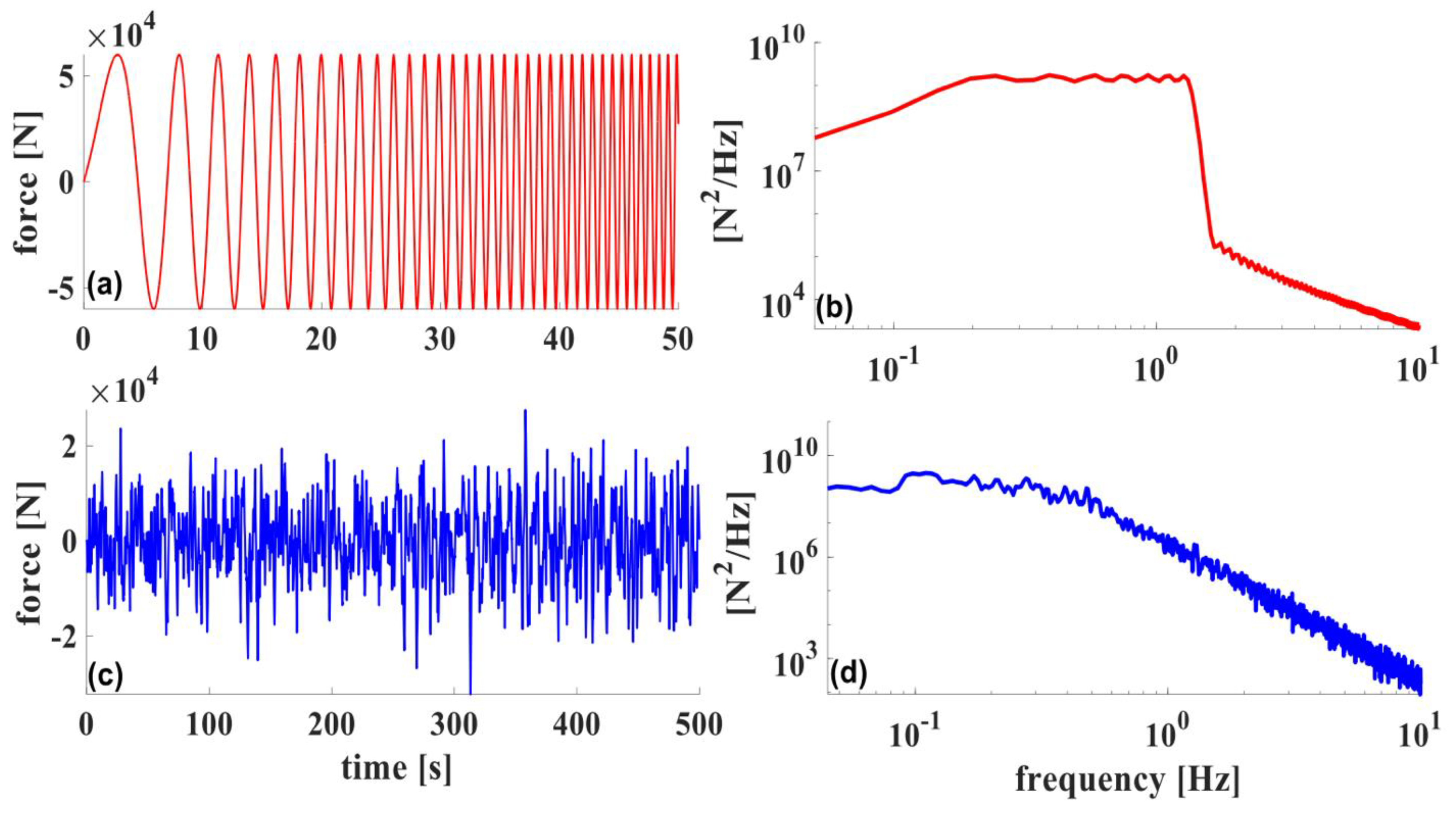
Excitation Forces
6. Optimization of TMDI and Equivalent TMD
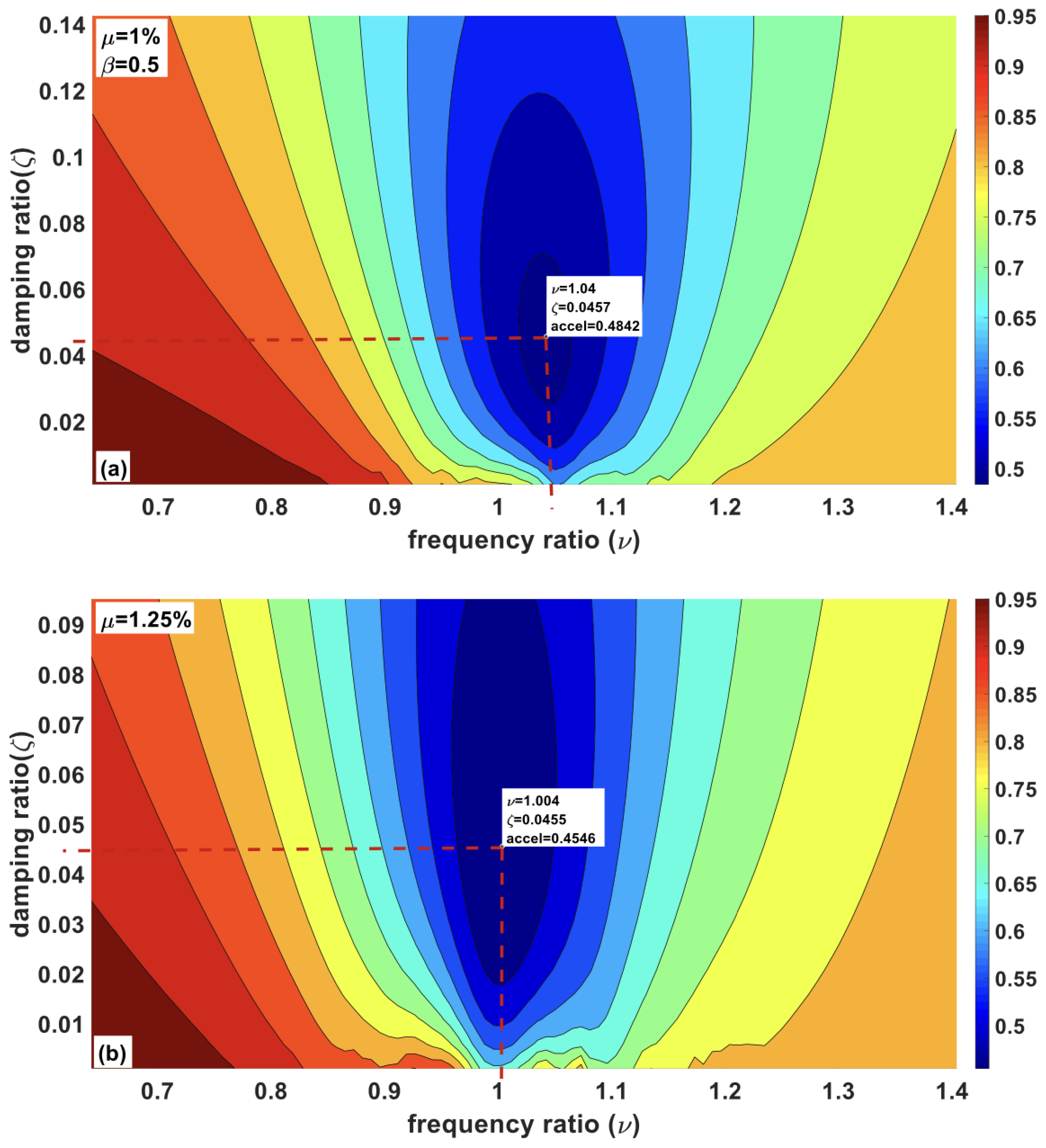
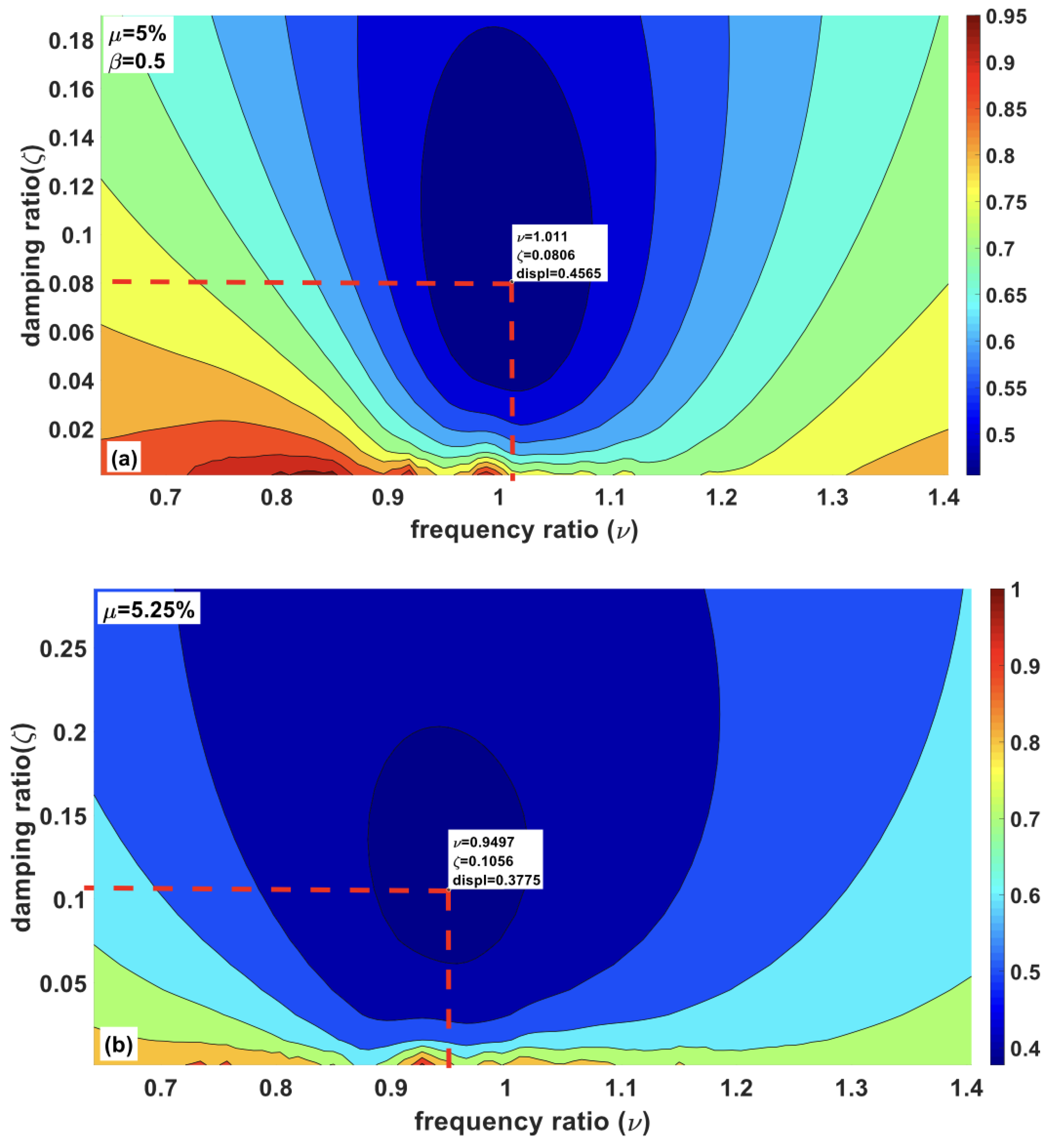
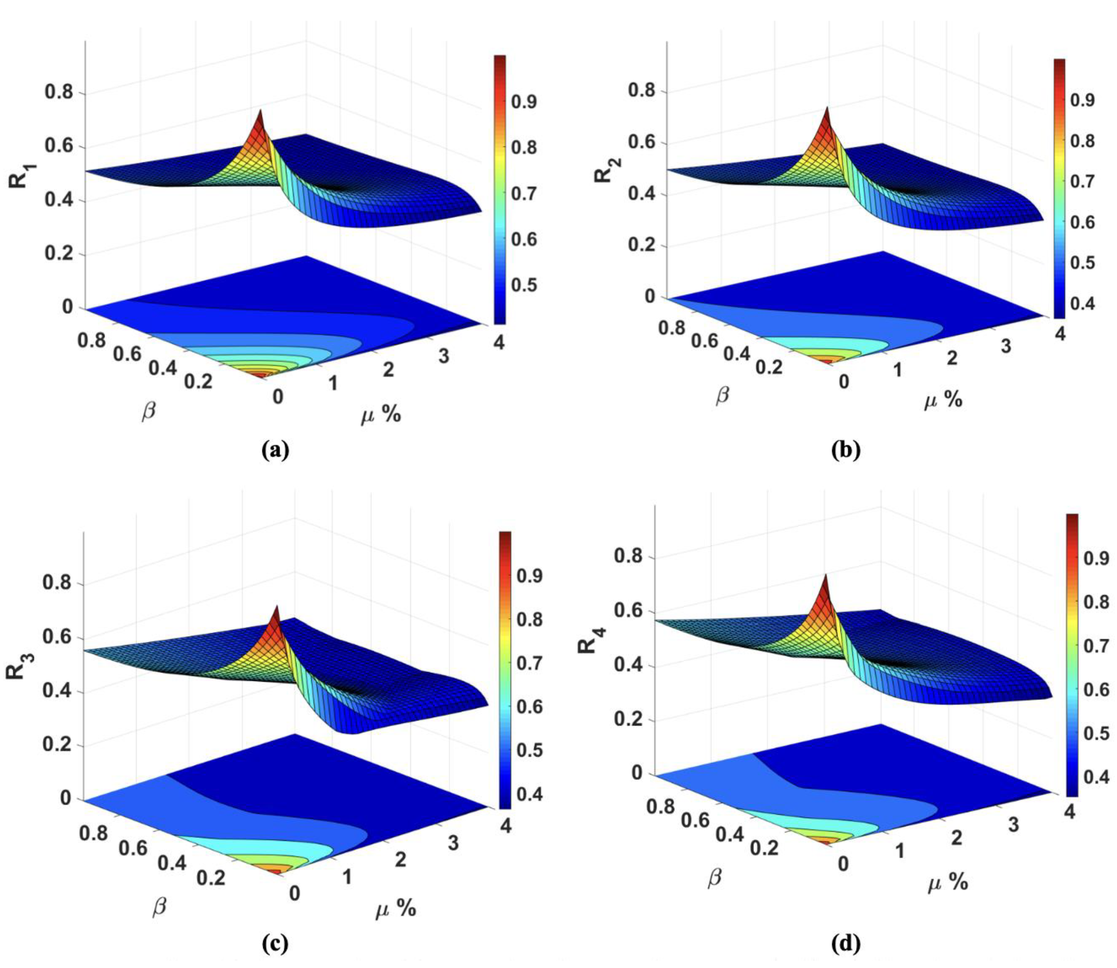
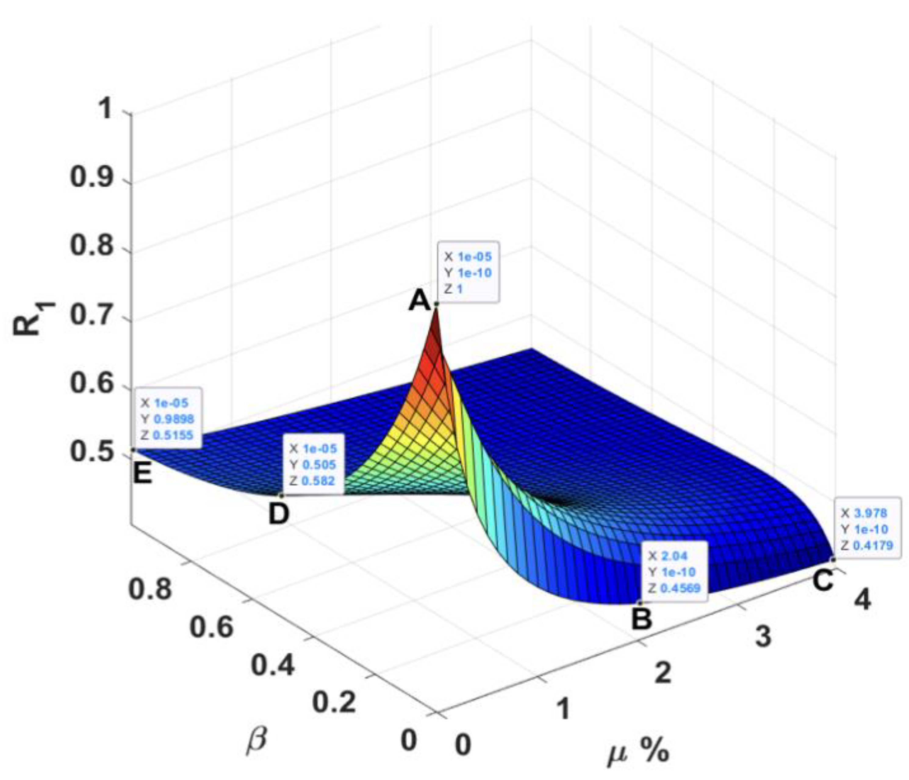
6.1. Effect of Mass Ratio and Inertance Ratios on the Performance of TMDI
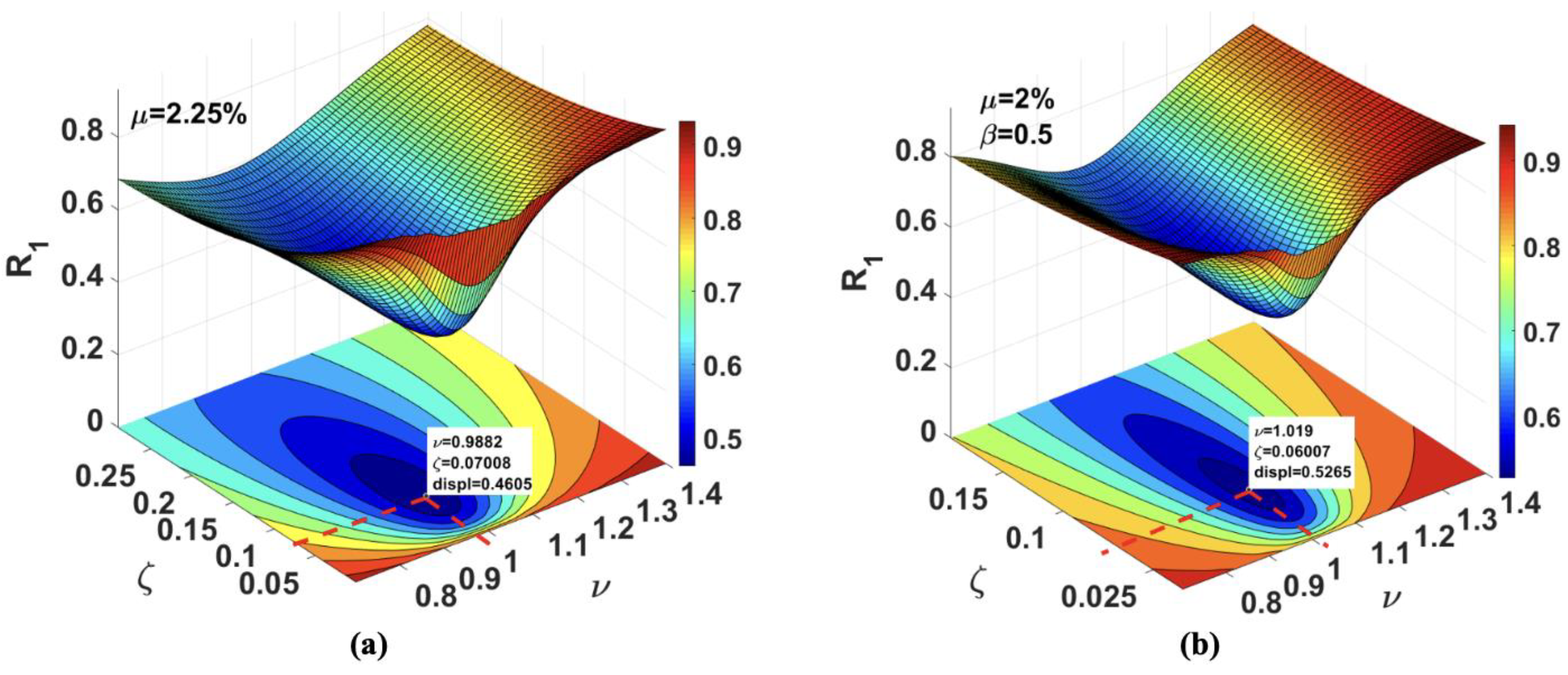
6.2. Performance under Variable Frequency Sinusoidal Excitations
7. Pounding Tuned Mass Damper
7.1. Proposed Pendulum PTMD
7.2. Modeling of a Building Equipped with Pendulum PTMD
8. Performance Comparison among TMD, TMDI, and Pendulum PTMD
8.1. Performance Comparison
8.2. Robustness
8.3. Prevention of Local Damage and Impact Noise Reduction
9. Conclusions
- ➢
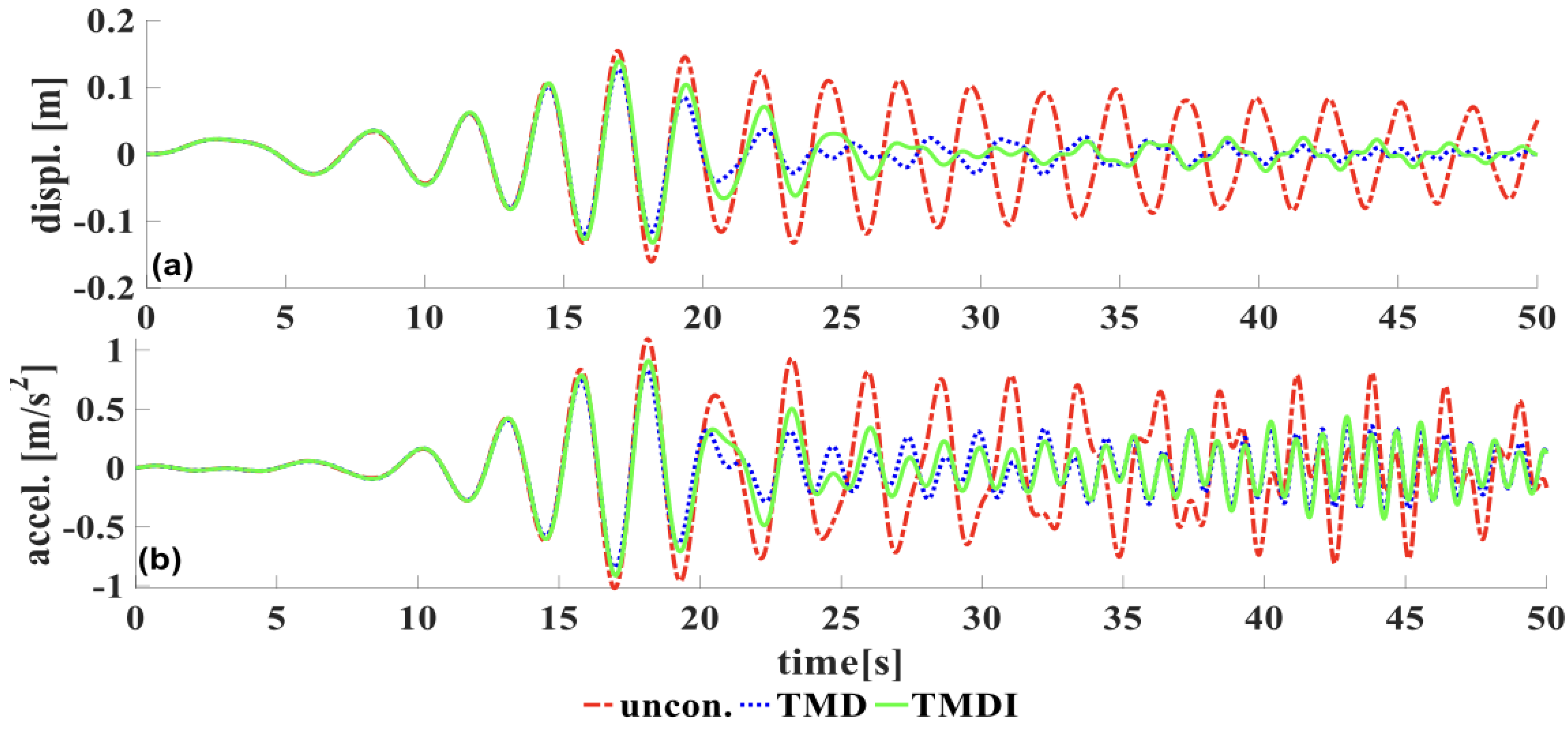
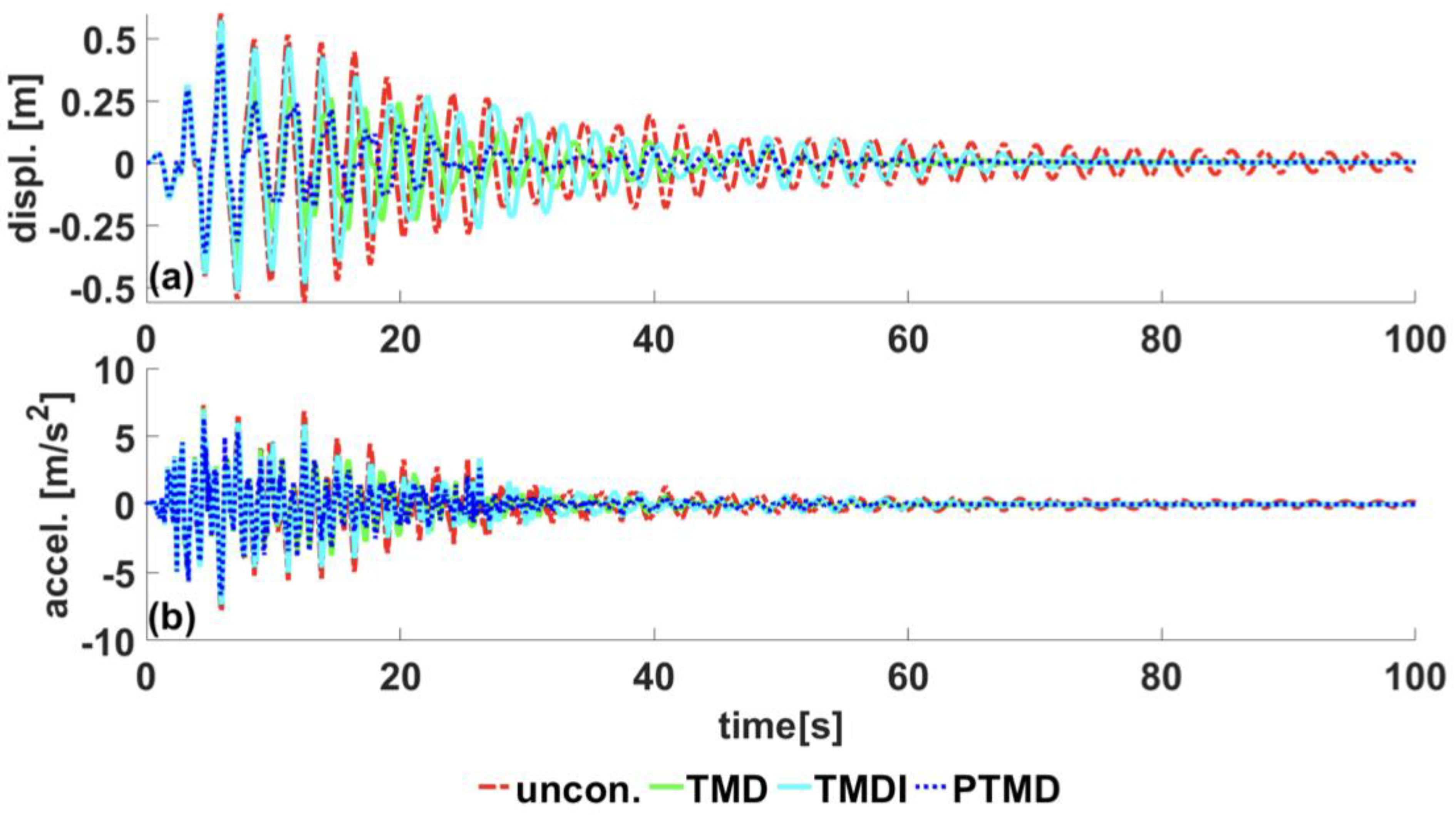
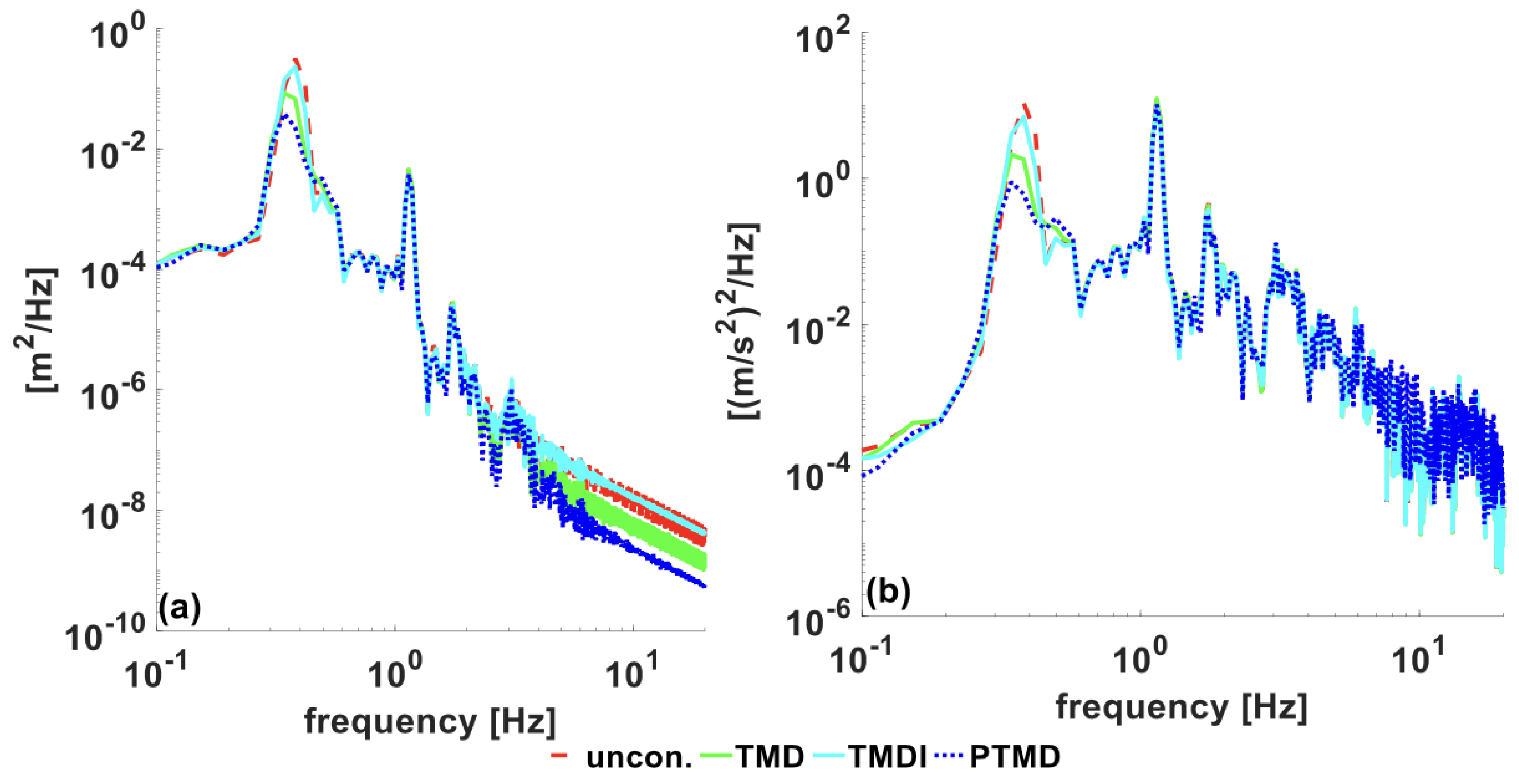
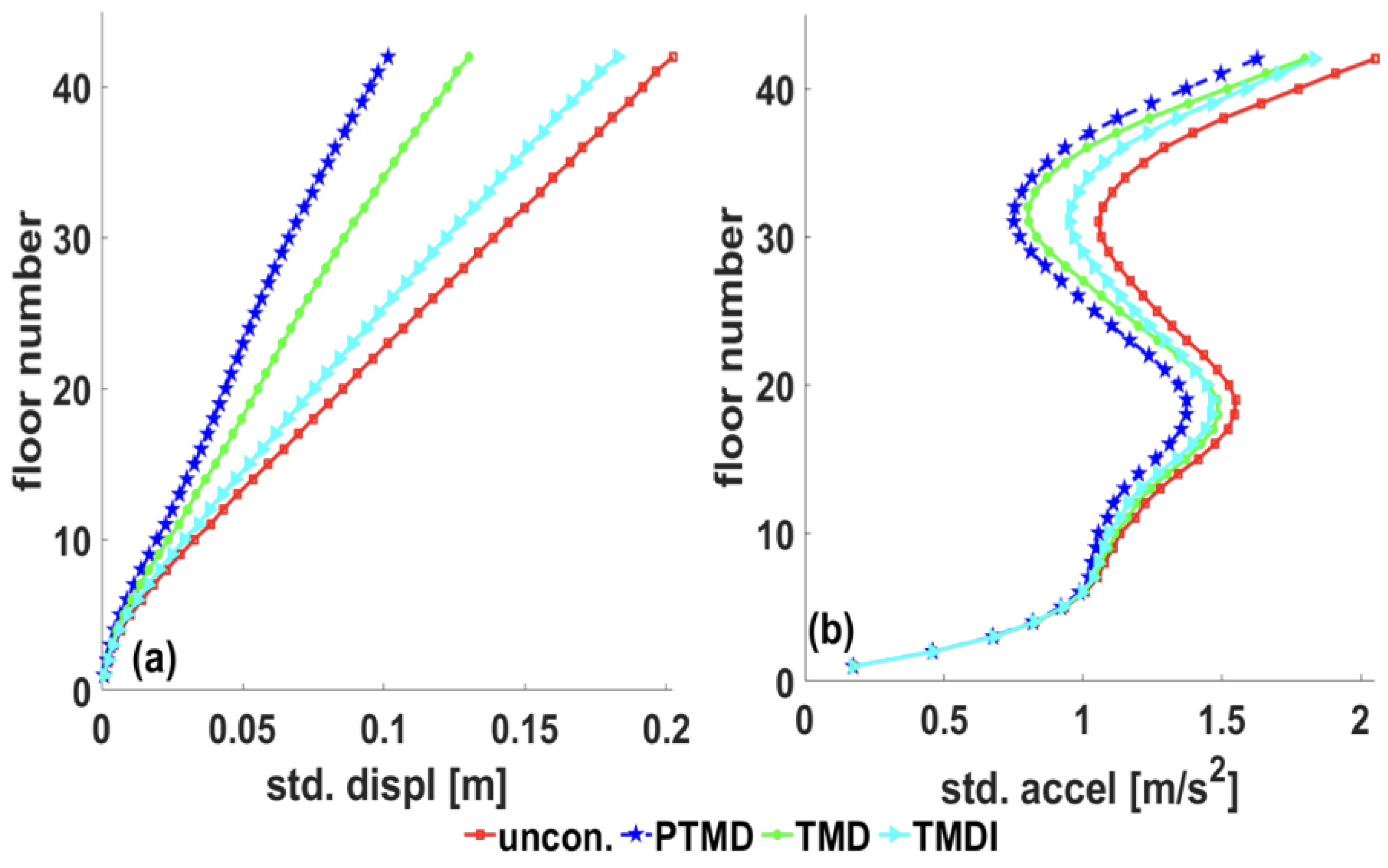
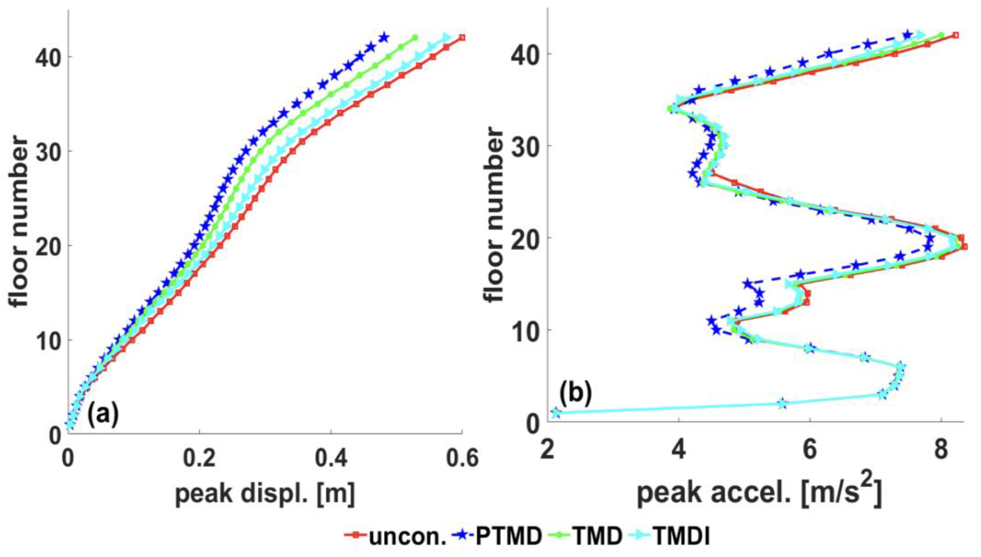
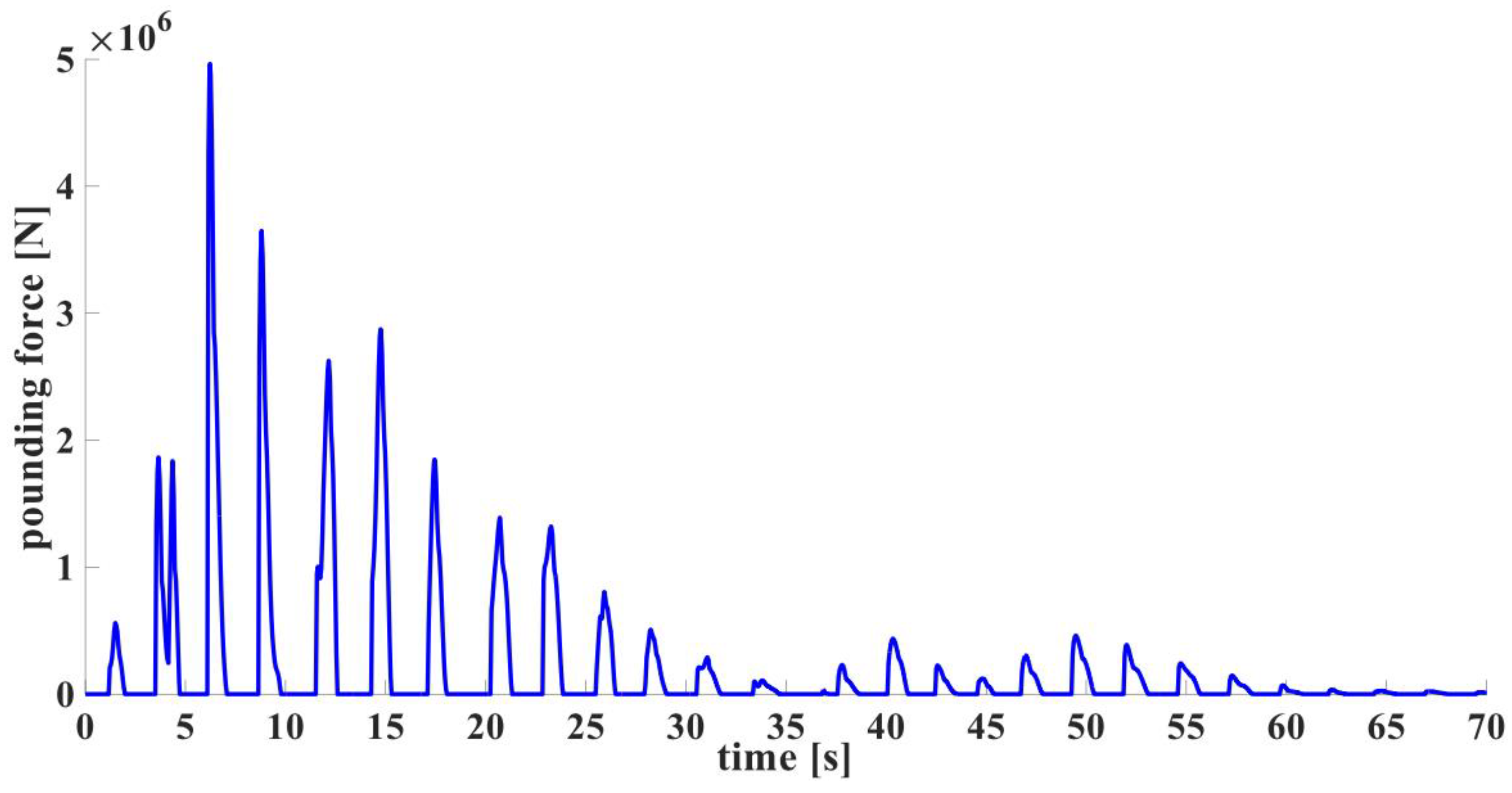
- A proposed robust pendulum PTMD with the same mass ratio as TMD and TMDI offers an excellent vibration reduction due to its superior energy dissipation at the pounding boundary. Under earthquake excitations, the proposed device can reduce the peak displacement at the top floor by 19.5%, while the TMD reduces the same response by 11.9%, and the TMDI reduces the response by 4.1%. In addition, the pendulum PTMD reduces top floor acceleration by 11%, while the TMD reduces it by a negligible amount. The robustness of the pendulum PTMD is superior compared to TMD/TMDI.
- ➢
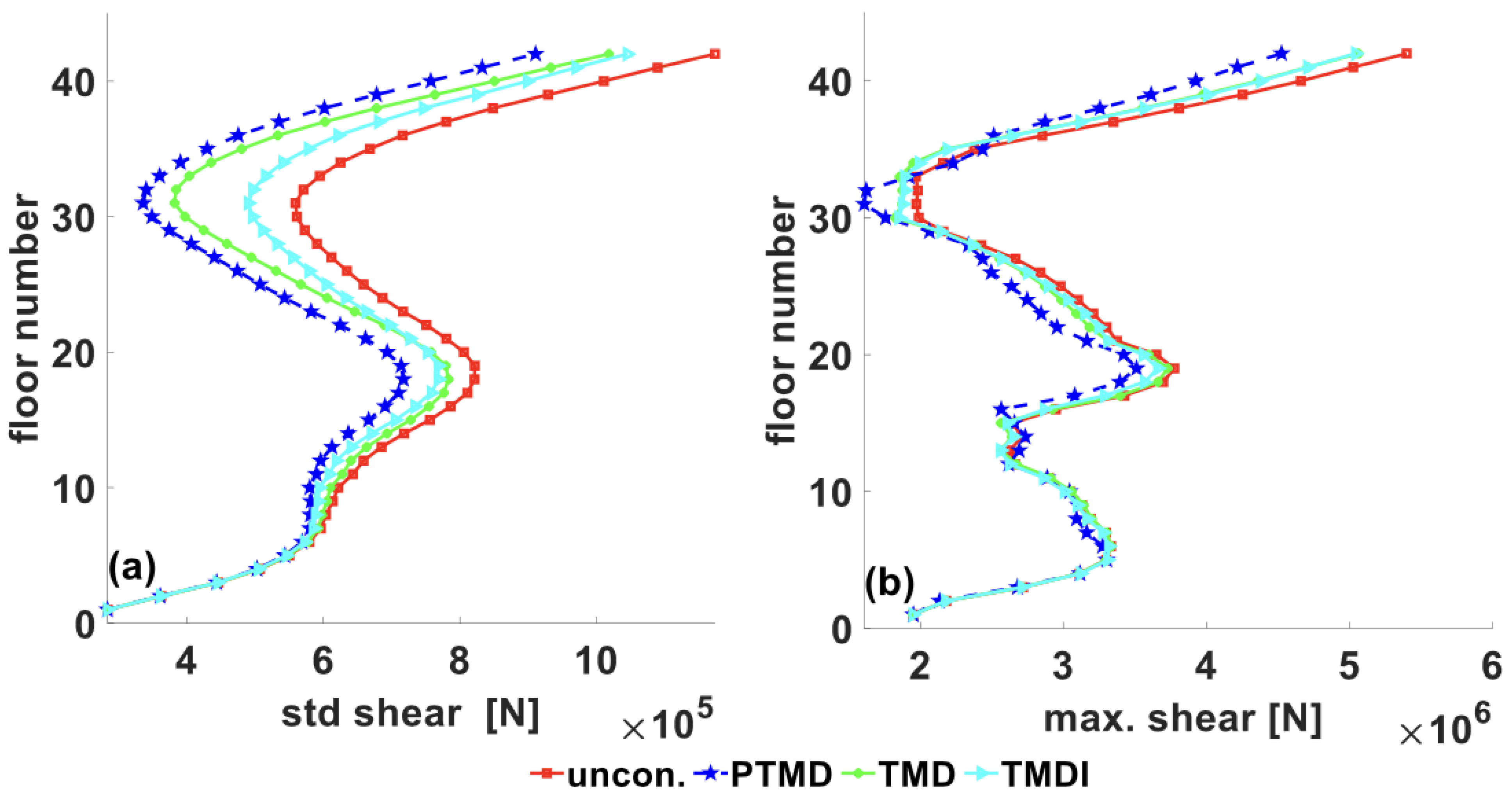
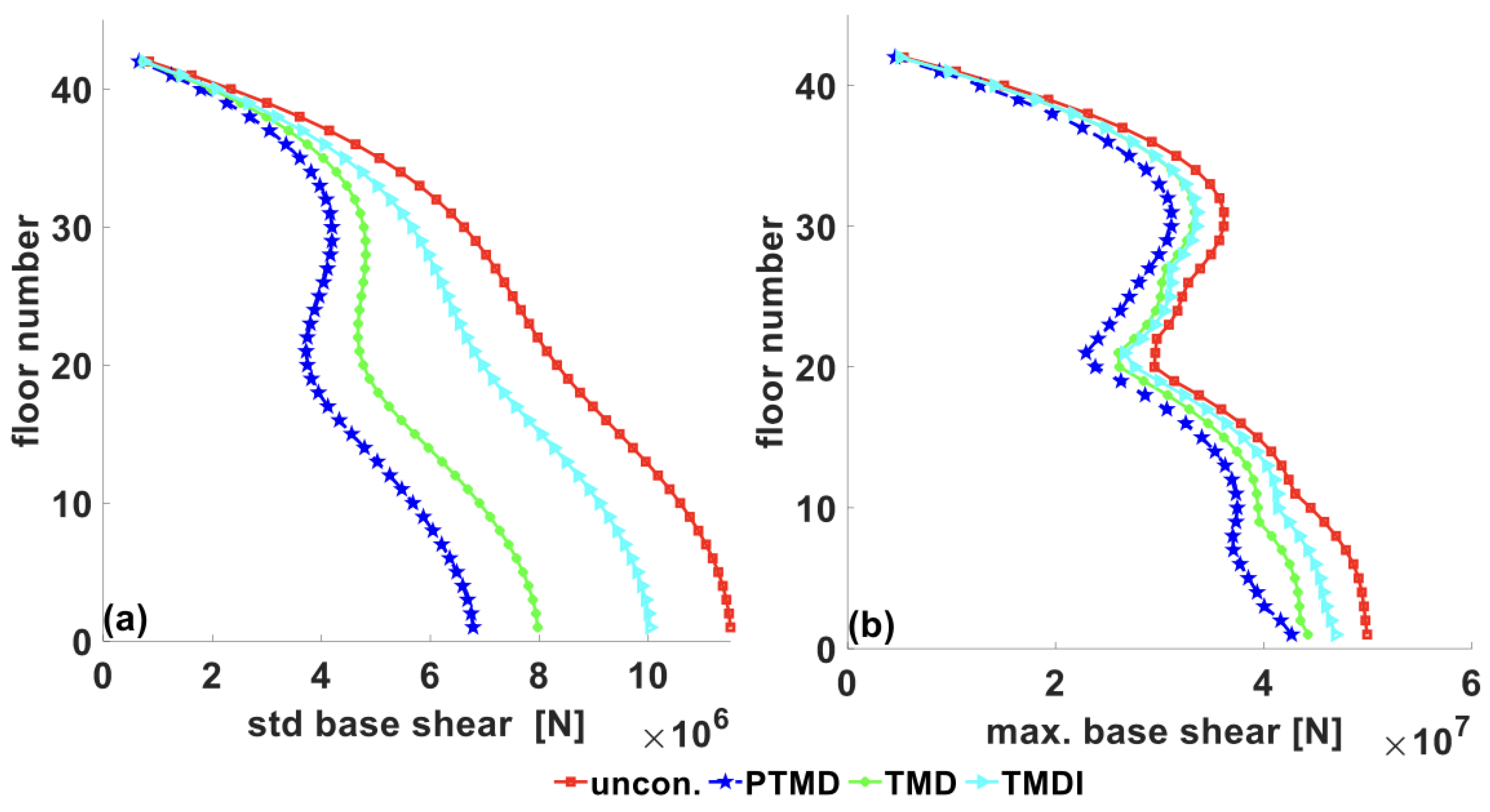
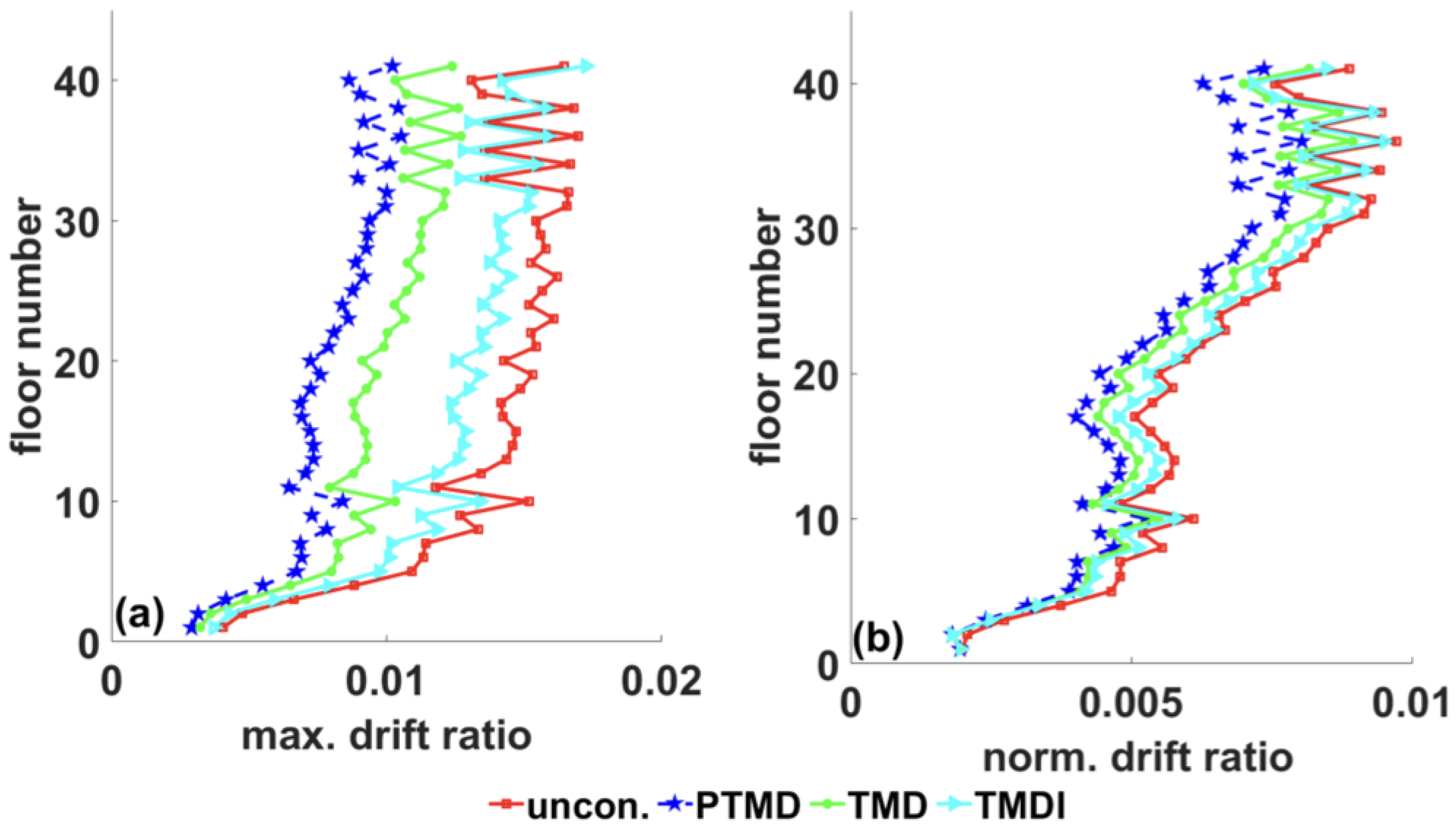
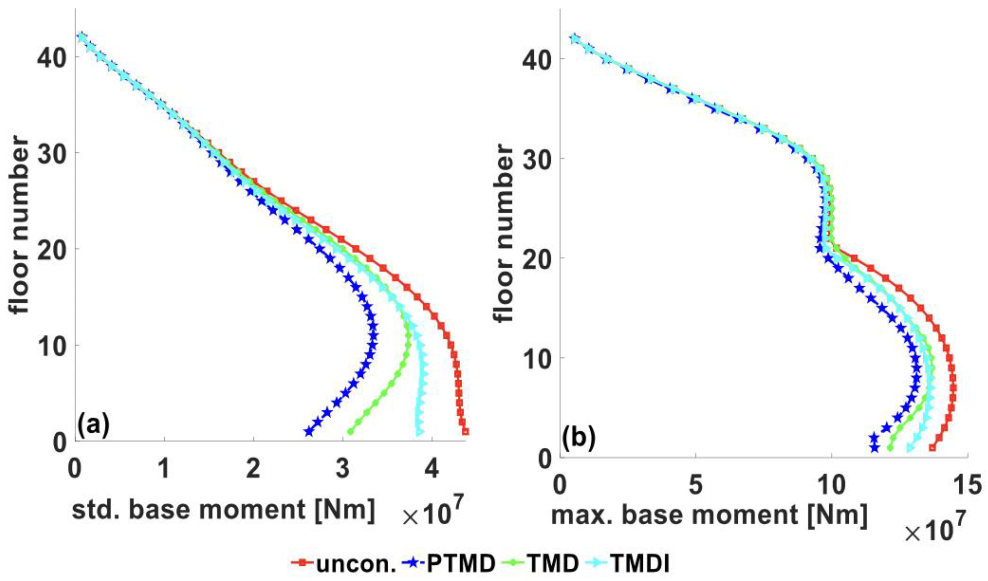
- The pendulum PTMD reduced the base shear force by 55.7% (STD) and 14.5% (peak value), the base moment by 41% (STD) and 14% (peak value), and the maximum inter-story drift ratio by 40% (peak value). The superior performance of the proposed pendulum PTMD in reducing peak accelerations reveals that the device can minimize damage to the building’s nonstructural elements (pipes, ceiling, partitions, etc.) during seismic events.
- ➢
- An equivalent TMD, including the physical mass of the inerter, is proposed for a one-to-one performance comparison between TMD and TMDI. The introduction of the inerter in a linear TMD may change the optimal device properties (damping ratio and tuning frequency, resulting in reduced energy dissipation). The results show that the equivalent TMD is better than TMDI in minimizing the building responses under variable frequency sinewave excitations unless the mass ratio is significantly small (<0.005).
- ➢
- The three devices can minimize acceleration better (compared to displacement) under filtered white noise (wind loads). However, the opposite is true under a variable frequency sinewave excitation (earthquake excitation). Nevertheless, due to the nonlinear behavior of the pendulum PTMD, higher modes are controlled, which results in a higher reduction in the acceleration response.
- ➢
- The control capabilities of the TMD increase with the increase in the mass ratio. However, the responses are sensitive to small mass ratios (0–2%). Similarly, for a given mass ratio, the vibration reduction capabilities of the TMDI increase as the inertance ratio increases. The structural responses are sensitive to the inertance ratio within the range of 0–0.5. Increasing the inertance ratio beyond 0.5 is inefficient and increases the device’s physical mass.
- ➢
- Pendulum PTMD has a potential application against multi-hazard (wind/earthquake) loads, resulting in sustainable and resilient future infrastructures. It can address the challenges of physical civil infrastructure to be resilient and sustainable over its service lifetime, under service and long-term conditions, including increased demands due to climate change adaptation and other emerging stressors (including single and multiple hazard events).
Author Contributions
Funding
Institutional Review Board Statement
Informed Consent Statement
Data Availability Statement
Conflicts of Interest
References
- Poirier, E.; Moudgil, M.; Fallahi, A.; Staub-French, S.; Tannert, T. Design and construction of a 53-meter-tall timber building at the University of British Columbia. In Proceedings of the World Conference on Timber Engineering, Vienna, Austria, 22–25 August 2016. [Google Scholar]
- Stepinac, M.; Šušteršič, I.; Gavrić, I.; Rajčić, V. Seismic design of timber buildings: Highlighted challenges and future trends. Appl. Sci. 2020, 10, 1380. [Google Scholar] [CrossRef]
- Morrison, M.J.; Kopp, G.A. performance of toe-nail connections under realistic wind loading. Eng. Struct. 2011, 33, 69–76. [Google Scholar] [CrossRef]
- He, J.; Pan, F.; Cai, C.S. A review of wood-frame low-rise building performance study under hurricane winds. Eng. Struct. 2017, 141, 512–529. [Google Scholar] [CrossRef]
- Somayaji, S. Low-rise timber buildings subjected to seismic wind and snow loads. J. Struct. Eng. 1985, 111, 1164–1166. [Google Scholar] [CrossRef]
- Rosowsky, D.; Schiff, S. What are our expectations, objectives, and performance requirements for wood structures in high wind regions? Nat. Hazards Rev. 2003, 4, 144–148. [Google Scholar] [CrossRef]
- Mensah, A.F.; Datin, P.L.; Prevatt, D.O.; Gupta, R.; van de Lindt, J.W. Database-assisted design methodology to predict wind-induced structural behavior of a light-framed wood building. Eng. Struct. 2011, 33, 674–684. [Google Scholar] [CrossRef]
- Schober, K.U.; Tannert, T. Hybrid connections for timber structures. Eur. J. Wood Wood Prod. 2016, 74, 369–377. [Google Scholar] [CrossRef]
- Branco, J.M.; Piazza, M.; Cruz, P.J.S. Experimental evaluation of different strengthening techniques of traditional timber connections. Eng. Struct. 2011, 33, 2259–2270. [Google Scholar] [CrossRef]
- Tesfamariam, S.; Stiemer, S.F. Special issue on performance of timber and hybrid structures. J. Perform. Constr. Facil. 2014, 28, 1–3. [Google Scholar] [CrossRef]
- Kocan, C.; Özgen, G.O. Investigation of the effect of structural damping on wind turbine wind-induced fatigue loads. Mech. Based Des. Struct. Mach. 2022, 1–26. [Google Scholar] [CrossRef]
- Huber, J.A.J.; Ekevad, M.; Girhammar, U.A.; Berg, S. Structural robustness and timber buildings—A review. Wood Mater. Sci. Eng. 2019, 14, 107–128. [Google Scholar] [CrossRef]
- Xie, Z.; Hu, X.; Du, H.; Zhang, X. Vibration behavior of timber-concrete composite floors under human-induced excitation. J. Build. Eng. 2020, 32, 101744. [Google Scholar] [CrossRef]
- Chapain, S.; Aly, A.M. Vibration attenuation in high-rise buildings to achieve system-level performance under multiple hazards. Eng. Struct. 2019, 197, 109352. [Google Scholar] [CrossRef]
- Khatibinia, M.; Gholami, H.; Kamgar, R. Optimal design of tuned mass dampers subjected to continuous stationary critical excitation. Int. J. Dyn. Control 2018, 6, 1094–1104. [Google Scholar] [CrossRef]
- Jeong, S.Y.; Kang, T.H.-K.; Yoon, J.K.; Klemencic, R. Seismic performance evaluation of a tall building: Practical modeling of surrounding basement structures. J. Build. Eng. 2020, 31, 101420. [Google Scholar] [CrossRef]
- Beskhyroun, S.; Navabian, N.; Wotherspoon, L.; Ma, Q. Dynamic behaviour of a 13-story reinforced concrete building under ambient vibration, forced vibration, and earthquake excitation. J. Build. Eng. 2020, 28, 101066. [Google Scholar] [CrossRef]
- Fragiacomo, M.; Dujic, B.; Sustersic, I. Elastic and ductile design of multi-storey crosslam massive wooden buildings under seismic actions. Eng. Struct. 2011, 33, 3043–3053. [Google Scholar] [CrossRef]
- Tassios, T.P. Seismic Design of Reinforced Concrete and Masonry Buildings; Wiley: New York, NY, USA, 1993; Volume 12. [Google Scholar]
- Pacchioli, S.; Pozza, L.; Trutalli, D.; Polastri, A. Earthquake-resistant CLT buildings stiffened with vertical steel ties. J. Build. Eng. 2021, 40, 102334. [Google Scholar] [CrossRef]
- Gavric, I.; Fragiacomo, M.; Ceccotti, A. Cyclic behavior of CLT wall systems: Experimental tests and analytical prediction models. J. Struct. Eng. 2015, 141, 04015034. [Google Scholar] [CrossRef]
- Igor, G.; Massimo, F.; Ario, C. Strength and deformation characteristics of typical X-lam connections. In Proceedings of the World Conference on Timber Engineering 2012, WCTE 2012, Auckland, New Zealand, 15–19 July 2012; pp. 146–155. Available online: http://support.sbcindustry.com/Archive/2012/july/Paper_092.pdf (accessed on 4 February 2023).
- Ceccotti, A.; Follesa, M.; Lauriola, M.P.; Sandhaas, C. Sofie Project–Test Results on the Lateral Resistance of Cross-Laminated Wooden Panels. In Proceedings of the First European Conference on Earthquake Engineering and Seismicity, Geneva, Switzerland, 3–8 September 2006; p. 10. Available online: http://www.timberengineering.it/Pubblicazioni/img/Articoli_scientifici/2006_ECEES_Testresults.pdf (accessed on 4 February 2023).
- Baker, J.W. Measuring bias in structural response caused by ground motion scaling. In Proceedings of the 8th Pacific Conference on Earthquake Engineering, Singapore, 5–7 December 2007; pp. 1–6. [Google Scholar] [CrossRef]
- Popovski, M.; Gavric, I. Performance of a 2-Story CLT House Subjected to Lateral Loads. J. Struct. Eng. 2016, 142, 1–12. [Google Scholar] [CrossRef]
- Reynolds, T.; Harris, R.; Chan, W.S. Dynamic response of tall timber buildings to wind load. In Proceedings of the35th Annual Symposium of IABSE/52nd Annual Symposium of IASS/6th International Conference on Space Structures, London, UK, 20–23 September 2011. [Google Scholar]
- Bezabeh, M.A.; Bitsuamlak, G.T.; Popovski, M.; Tesfamariam, S. Probabilistic serviceability-performance assessment of tall mass-timber buildings subjected to stochastic wind loads: Part I—Structural design and wind tunnel testing. J. Wind Eng. Ind. Aerodyn. 2018, 181, 85–103. [Google Scholar] [CrossRef]
- Bezabeh, M.A.; Gairola, A.; Bitsuamlak, G.T.; Popovski, M.; Tesfamariam, S. Structural performance of multi-story mass-timber buildings under tornado-like wind field. Eng. Struct. 2018, 177, 519–539. [Google Scholar] [CrossRef]
- Johansson, M.; Linderholt, A.; Jarnerö, K.; Landel, P. Tall timber buildings—A preliminary study of wind-induced vibrations of a 22-storey building. In Proceedings of the World Conference on Timber Engineering (WCTE 2016), Vienna, Austria, 22–25 August 2016. [Google Scholar]
- Dadkhaha, M.; Kamgar, R.; Heidarzadeh, H. Reducing the Cost of Calculations for Incremental Dynamic Analysis of Building Structures Using the Discrete Wavelet Transform. Eng. J. Earthq. Eng. 2022, 26, 3317–3342. [Google Scholar] [CrossRef]
- Skidmore Owings and Merrill (SOM LLP). Timber Tower Research Project; Skidmore Owings and Merrill (SOM LLP): Chicago, IL, USA, 2013. [Google Scholar]
- Manual for Engineered Wood Construction; American Wood Council: Leesburg, VA, USA, 2018.
- van de Kuilen, J.W.G.; Ceccotti, A.; Xia, Z.; He, M. Very tall wooden buildings with Cross Laminated Timber. Procedia Eng. 2011, 14, 1621–1628. [Google Scholar] [CrossRef]
- Zhang, X. Seismic Design of Timber Steel Hybrid High-Rise Buildings. Ph.D. Thesis, University of Brithish Columbia, Vancouver, BC, Canada, 2017. [Google Scholar]
- Karacabeyli, E.; Brad, D. Hand Book Cross Laminated Timber; SP-529E; FPInnovations, Spec. Publ.: Leesburg, VA, USA, 2013; p. 572. Available online: https://cdn2.hubspot.net/hubfs/5577290/PDFs/CLT%20Handbook/CLT_USA-Complete-document-Think_Wood.pdf (accessed on 4 February 2023).
- Tamura, Y.; Akihito, Y. Amplitude Dependency of Damping in Buildings. In Proceedings of the Structures Congress 2008: 18th Analysis and Computation Specialty Conference, Vancouver, BC, Canada, 24–26 April 2008. [Google Scholar]
- Aly, A.M. Pressure integration technique for predicting wind-induced response in high-rise buildings. Alex. Eng. J. 2013, 52, 717–731. [Google Scholar] [CrossRef]
- Chowdhury, I.; Dasgupta, S.P. Computation of Rayleigh damping coefficients for large systems. Electron. J. Geotech. Eng. 2003, 8, 1–11. [Google Scholar]
- Housner, G.W.; Bergman, L.A.; Caughey, T.K.; Chassiakos, A.G. Structural control: Past, present, and future. J. Eng. Mech. 1997, 123, 897–971. [Google Scholar] [CrossRef]
- Spencer, B.F.J.; Nagarajah, S. State of the Art of Structural Control. J. Struct. Eng. 2003, 129, 845–846. [Google Scholar] [CrossRef]
- Tanveer, M.; Usman, M.; Khan, I.U.; Farooq, S.H.; Hanif, A. Material optimization of tuned liquid column ball damper (TLCBD) for the vibration control of multi-storey structure using various liquid and ball densities. J. Build. Eng. 2020, 32, 101742. [Google Scholar] [CrossRef]
- Reiterer, M.; Schellander, J. A Novel Single Tube Semi-Active Tuned Liquid Gas Damper for Suppressing Horizontal Vibrations of Tower-like Structures. Appl. Sci. 2022, 12, 3301. [Google Scholar]
- Bigdeli, Y.; Kim, D. Damping effects of the passive control devices on structural vibration control: TMD, TLC and TLCD for varying total masses. KSCE J. Civ. Eng. 2016, 20, 301–308. [Google Scholar] [CrossRef]
- Bigdeli, Y.; Kim, D. Response control of irregular structures using structure-TLCD coupled system under seismic excitations. KSCE J. Civ. Eng. 2015, 19, 672–681. [Google Scholar] [CrossRef]
- Bigdeli, Y.; Kim, D.; Chang, S. Vibration control of 3D irregular buildings by using developed neuro-controller strategy. Struct. Eng. Mech. 2014, 49, 687–703. [Google Scholar] [CrossRef]
- Dadkhah, M.; Kamgar, R.; Heidarzadeh, H.; Jakubczyk-Gałczyńska, A.; Jankowski, R. Improvement of Performance Level of Steel Moment-Resisting Frames Using Tuned Mass Damper System. Appl. Sci. 2020, 10, 3403. [Google Scholar] [CrossRef]
- Nakano, Y.; Kishi, T.; Takahara, H. Experimental Study on Application of Tuned Mass Dampers for Chatter in Turning of a Thin-Walled Cylinder. Appl. Sci. 2021, 11, 12070. [Google Scholar] [CrossRef]
- Aksoy, T.; Özgen, G.O.; Acar, B. Design of a tuned vibration absorber for a slender hollow cylindrical structure. Mech. Based Des. Struct. Mach. 2020, 48, 615–648. [Google Scholar] [CrossRef]
- Longarini, N.; Cabras, L.; Zucca, M.; Chapain, S.; Aly, A.M. Structural Improvements for Tall Buildings under Wind Loads: Comparative Study. Shock Vib. 2017, 2017, 2031248. [Google Scholar] [CrossRef]
- Abdelnaeem, M.; Elsouhily, B.; Elgamal, H. Multi Objective Optimization of a Quarter Car Model Fitted with an MR-Damper. Int. J. Adv. Mech. Aeronaut. Eng. 2018, 5, 7–13. [Google Scholar]
- Basili, M.; de Angelis, M. Experimental Dynamic Response of a Multi-Story Frame Structure Equipped with Non-Conventional TMD Implemented via Inter-Story Isolation. Appl. Sci. 2022, 12, 9153. [Google Scholar] [CrossRef]
- Ozturk, B.; Cetin, H.; Dutkiewicz, M.; Aydin, E.; Farsangi, E.N. On the Efficacy of a Novel Optimized Tuned Mass Damper for Minimizing Dynamic Responses of Cantilever Beams. Appl. Sci. 2022, 12, 7878. [Google Scholar] [CrossRef]
- Ghoniem, M.; Awad, T.; Mokhiamar, O. Control of a new low-cost semi-active vehicle suspension system using artificial neural networks. Alex. Eng. J. 2020, 59, 4013–4025. [Google Scholar] [CrossRef]
- Kareem, A.; Kijewski, T.; Tamura, Y. Mitigation of motions of tall buildings with specific examples of recent applications. Wind Struct. An Int. J. 1999, 2, 201–251. [Google Scholar] [CrossRef]
- Aly, A.M. Proposed robust tuned mass damper for response mitigation in buildings exposed to multidirectional wind. Struct. Des. Tall Spec. Build. 2014, 23, 664–691. [Google Scholar] [CrossRef]
- Salimi, M.; Kamgar, R.; Heidarzadeh, H. An evaluation of the advantages of friction TMD over conventional TMD. Innov. Infrastruct. Solut. 2021, 6, 95. [Google Scholar] [CrossRef]
- Martinez-Paneda, M.; Elghazouli, A.Y. An integrated damping system for tall buildings. Struct. Des. Tall Spec. Build. 2020, 29, e1724. [Google Scholar] [CrossRef]
- Kamgar, R.; Gholami, F.; Sanayei, H.R.Z.; Heidarzadeh, H. Modified Tuned Liquid Dampers for Seismic Protection of Buildings Considering Soil–Structure Interaction Effects. Iran. J. Sci. Technol. Trans. Civ. Eng. 2020, 44, 339–354. [Google Scholar] [CrossRef]
- Guan, D.; Cong, X.; Li, J.; Wang, P.; Yang, Z.; Jing, X. Theoretical modeling and optimal matching on the damping property of mechatronic shock absorber with low speed and heavy load capacity. J. Sound Vib. 2022, 535, 117113. [Google Scholar] [CrossRef]
- Jafari, M.; Alipour, A. Methodologies to mitigate wind-induced vibration of tall buildings: A state-of-the-art review. J. Build. Eng. 2021, 33, 101582. [Google Scholar] [CrossRef]
- Weber, F.; Borchsenius, F.; Distl, J.; Braun, C. Performance of Numerically Optimized Tuned Mass Damper with Inerter (TMDI). Appl. Sci. 2022, 12, 6204. [Google Scholar]
- Marian, L.; Giaralis, A. Optimal design of a novel tuned mass-damper-inerter (TMDI) passive vibration control configuration for stochastically support-excited structural systems. Probabilistic Eng. Mech. 2014, 38, 156–164. [Google Scholar] [CrossRef]
- Petrini, F.; Giaralis, A.; Wang, Z. Optimal tuned mass-damper-inerter (TMDI) design in wind-excited tall buildings for occupants’ comfort serviceability performance and energy harvesting. Eng. Struct. 2020, 204, 109904. [Google Scholar] [CrossRef]
- Smith, M.C. Synthesis of mechanical networks: The inerter. IEEE Trans. Automat. Contr. 2002, 47, 1648–1662. [Google Scholar] [CrossRef]
- Papageorgiou, C.; Smith, M.C. Laboratory experimental testing of inerters. In Proceedings of the 44th IEEE Conference on Decision and Control, Seville, Spain, 15 December 2005; pp. 3351–3356. [Google Scholar] [CrossRef]
- Chen, M.Z.Q.; Hu, Y. Inerter and Its Application in Vibration Control Systems; Springer: Singapore, 2019; pp. 1–122. [Google Scholar] [CrossRef]
- Nakaminami, S.; Kida, H.; Ikago, K.; Inoue, N. Dynamic testing of a full-scale hydraulic inerter-damper for the seismic protection of civil structures. In Proceedings of the 7th International Conference on Advances in Experimental Structural Engineering, AESE 2017, Pavia, Italy, 6–8 September 2017; pp. 41–54. [Google Scholar] [CrossRef]
- Smith, M.C. Performance Benefits in Passive Vehicle Suspensions Employing Inerters. Taylor Fr. 2004, 42, 235–257. [Google Scholar] [CrossRef]
- Caicedo, D.; Lara-Valencia, L.; Blandon, J.; Graciano, C. Seismic response of high-rise buildings through metaheuristic-based optimization using tuned mass dampers and tuned mass dampers inerter. J. Build. Eng. 2021, 34, 101927. [Google Scholar] [CrossRef]
- Madhamshetty, K.; Manimala, J.M. Low-rate characterization of a mechanical inerter. Machines 2018, 6, 32. [Google Scholar] [CrossRef]
- Wang, Q.; Qiao, H.; de Domenico, D.; Zhu, Z.; Xie, Z. Wind-induced response control of high-rise buildings using inerter-based vibration absorbers. Appl. Sci. 2019, 9, 5045. [Google Scholar] [CrossRef]
- de Domenico, D.; Ricciardi, G. An enhanced base isolation system equipped with optimal tuned mass damper inerter (TMDI). Earthq. Eng. Struct. Dyn. 2018, 47, 1169–1192. [Google Scholar] [CrossRef]
- Attaway, S. MATLAB: A Practical Introduction to Programming and Problem Solving, 5th ed.; Butterworth-Heinemann: Woburn, MA, USA, 2018. [Google Scholar]
- Liberty, S.; Ogata, K.; Liberty, S. Modern Control Engineering; Elsevier: Amsterdam, The Netherlands, 1972; Volume 17. [Google Scholar]
- Li, Q.S.; Zhi, L.H.; Tuan, A.Y.; Kao, C.S.; Su, S.C.; Wu, C.F. Dynamic behavior of Taipei 101 tower: Field measurement and numerical analysis. J. Struct. Eng. 2011, 137, 143–155. [Google Scholar] [CrossRef]
- Mazza, F.; Sisinno, S. Nonlinear dynamic behavior of base-isolated buildings with the friction pendulum system subjected to near-fault earthquakes. Mech. Based Des. Struct. Mach. 2017, 45, 331–344. [Google Scholar]
- Zhang, P.; Song, G.; Li, H.N.; Lin, Y.X. Seismic control of power transmission tower using pounding TMD. J. Eng. Mech. 2013, 139, 1395–1406. [Google Scholar] [CrossRef]
- Song, G.B. Vibration control of a pipeline structure using pounding tuned mass damper. J. Eng. Mech. 2016, 142, 04016031. [Google Scholar] [CrossRef]
- Patil, D.; Kalia, A.; Ho, S.C.M.; Zhang, P.; Lara, M.; Song, G. Pounding Tuned Mass Damper (PTMD): An innovative damper for subsea pipeline and jumper vibration controls. In Proceedings of the Offshore Mediterranean Conference and Exhibition, Ravenna, Italy, 29–March 2017; pp. 1–11. [Google Scholar] [CrossRef]
- Li, H.; Zhang, P.; Song, G.; Patil, D.; Mo, Y. Robustness study of the pounding tuned mass damper for vibration control of subsea jumpers. Smart Mater. Struct. 2015, 24, 095001. [Google Scholar] [CrossRef]
- Zhang, P.; Li, L.; Patil, D.; Singla, M.; Li, H.; Mo, Y.L.; Song, G. Parametric study of pounding tuned mass damper for subsea jumpers. Smart Mater. Struct. 2015, 25, 015028. [Google Scholar] [CrossRef]
- Nguyen, X.-T.; Miura, N.; Nguyen, V.-T.; Bui, T.-L. Design of multiple tuned mass damper devices and application to response control of bridge under external force. Mech. Based Des. Struct. Mach. 2021, 1–18. [Google Scholar] [CrossRef]
- Yin, X.; Liu, Y.; Song, G.; Mo, Y.L. Suppression of bridge vibration induced by moving vehicles using pounding tuned mass dampers. J. Bridg. Eng. 2018, 23, 1–14. [Google Scholar] [CrossRef]
- Wang, W.; Hua, X. Modeling, simulation, and validation of a pendulum-pounding tuned mass damper for vibration control. Struct. Control. Health Monit. 2019, 26, e2326. [Google Scholar] [CrossRef]
- Chapain, S.; Aly, A.M. Vibration Attenuation in Wind Turbines: A Proposed Robust Pendulum Pounding TMD. Eng. Struct. 2021, 233, 111891. [Google Scholar] [CrossRef]
- Jankowski, R. pounding force response spectrum under earthquake excitation. Eng. Struct. 2006, 28, 1149–1161. [Google Scholar] [CrossRef]
- Muthukumar, S.; DesRoches, R. A Hertz contact model with nonlinear damping for pounding simulation. Earthq. Eng. Struct. Dyn. 2006, 35, 811–828. [Google Scholar] [CrossRef]
- Ye, K.; Li, L.; Zhu, H. A modified Kelvin impact model for pounding simulation of base-isolated building with adjacent structures. Earthq. Eng. Eng. Vib. 2009, 8, 433–446. [Google Scholar] [CrossRef]
- Maison, B.F.; Kasai, K. Dynamics of pounding when two buildings collide. Earthq. Eng. Struct. Dyn. 1992, 21, 771–786. [Google Scholar] [CrossRef]
- Jankowski, R. Nonlinear viscoelastic modelling of earthquake-induced structural pounding. Earthq. Eng. Struct. Dyn. 2005, 34, 595–611. [Google Scholar] [CrossRef]
- Pratesi, F.; Sorace, S.; Terenzi, G. Analysis and mitigation of seismic pounding of a slender R/C bell tower. Eng. Struct. 2014, 71, 23–34. [Google Scholar] [CrossRef]
- PEER. Strong Ground Motion Databases. 2021. Available online: https://peer.berkeley.edu/peer-strong-ground-motion-databases (accessed on 4 February 2023).
- International Code Council. Vol 2—Structural Engineering Design Provisions; International Conference of Building Officials: Whittier, CA, USA, 1997. [Google Scholar]
- Raheem, S. Seismic pounding between adjacent building structures. Electron. J. Struct. Eng. 2006, 6, 66–74. Available online: http://www.ejse.org/Archives/Fulltext/2006/200608.pdf (accessed on 4 February 2023).
- Park, S.H.; Lee, P.J. Effects of floor impact noise on psychophysiological responses. Build. Environ. 2017, 116, 173–181. [Google Scholar] [CrossRef]
- Akay, A. A review of impact noise. J. Acoust. Soc. Am. 1978, 64, 977–987. [Google Scholar] [CrossRef]
- Tandon, N. Noise-reducing designs of machines and structures. Sadhana-Acad. Proc. Eng. Sci. 2000, 25, 331–339. [Google Scholar] [CrossRef]


| Building Name | Height (m) | Year Completed | Country |
|---|---|---|---|
| Stadthaus | 29 m | 2007 | United Kingdom |
| Life Cycle Tower | 27 m | 2012 | Austria |
| Forte | 32 m | 2012 | Australia |
| Treet | 49 m | 2014 | Norway |
| Brock Common UBC | 53 m | 2017 | Canada |
| Mjøstårnet | 85 m | 2019 | Norway |
| Ascent MKE | 87 m | 2022 | United States of America |
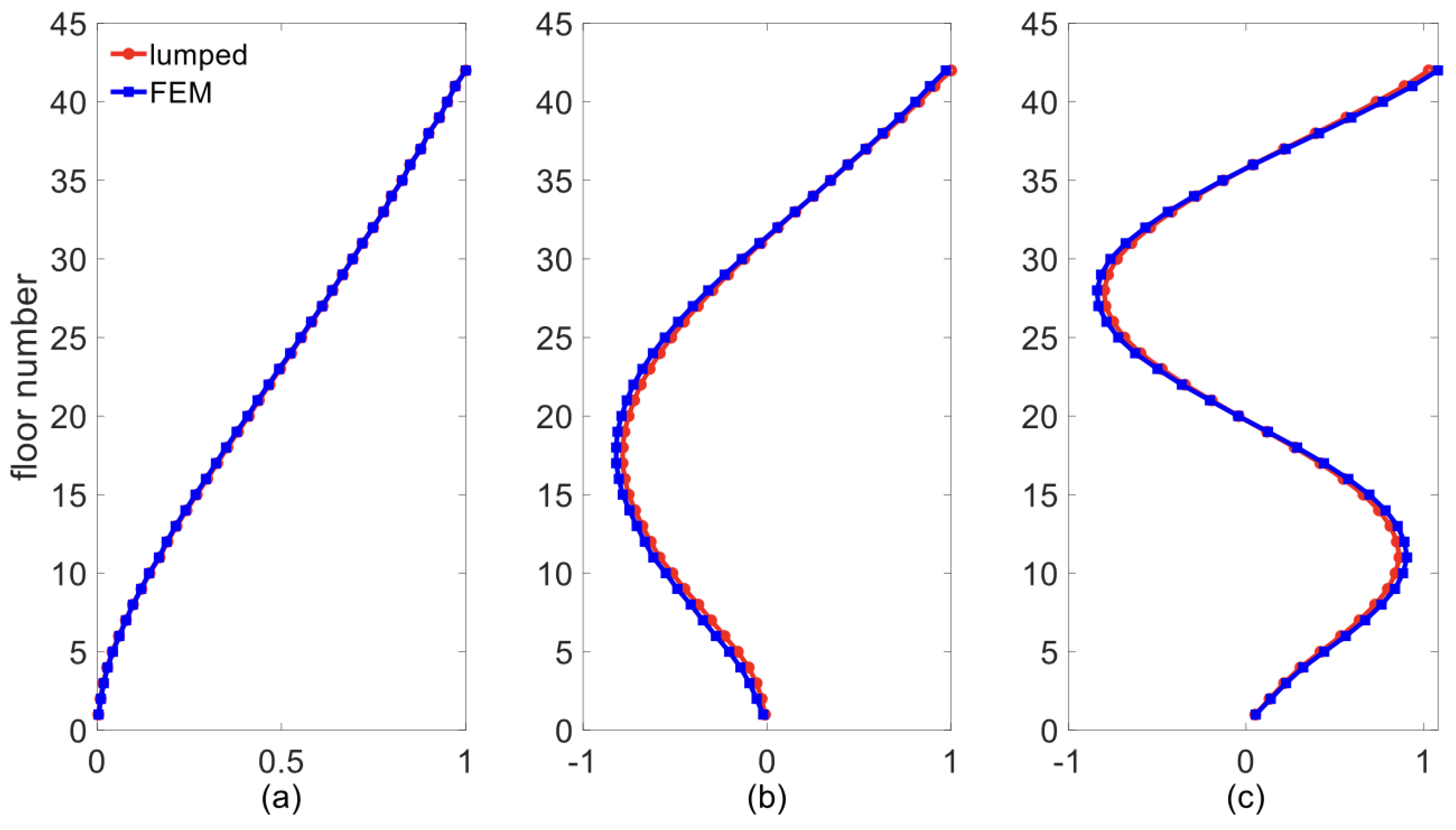
| Modes | Lumped Mass Model | 3D FEM |
|---|---|---|
| 1 | 0.389 Hz | 0.389 Hz |
| 2 | 1.466 Hz | 1.465 Hz |
| 3 | 1.984 Hz | 1.991 Hz |
| TMD Parameters | % Age Reduction | TMDI Parameters | % Age Reduction | |||||||
|---|---|---|---|---|---|---|---|---|---|---|
| (%) | Accel. | Displ. | (%) | Beta | Accel. | Displ. | ||||
| 0.75 | 1.004 | 0.044 | 34.46 | -- | 0.5 | 0.5 | 1.034 | 0.046 | 36.05 | -- |
| 0.996 | 0.044 | -- | 39.7 | 1.027 | 0.046 | -- | 40.06 | |||
| 1.25 | 1.004 | 0.053 | 39.11 | -- | 1 | 0.5 | 1.034 | 0.053 | 37.56 | -- |
| 0.988 | 0.053 | -- | 45.21 | 1.027 | 0.053 | -- | 41.36 | |||
| 2.25 | 0.995 | 0.070 | 44.20 | -- | 2 | 0.5 | 1.027 | 0.060 | 40.21 | -- |
| 0.988 | 0.070 | -- | 51.32 | 1.019 | 0.053 | -- | 44.30 | |||
| 3.25 | 0.995 | 0.090 | 47.32 | -- | 3 | 0.5 | 1.027 | 0.066 | 42.41 | -- |
| 0.980 | 0.090 | -- | 54.94 | 1.011 | 0.066 | -- | 46.66 | |||
| 4.25 | 0.995 | 0.110 | 49.53 | -- | 4 | 0.5 | 1.019 | 0.073 | 44.45 | -- |
| 0.972 | 0.100 | -- | 57.46 | 1.011 | 0.066 | -- | 48.68 | |||
| 5.25 | 0.9959 | 0.1001 | 51.05 | -- | 5 | 0.5 | 1.019 | 0.0867 | 46.19 | -- |
| 0.9651 | 0.1101 | -- | 59.37 | 1.004 | 0.8006 | -- | 50.46 | |||
| TMD Parameters | % Age Reduction | TMDI Parameters | % Age Reduction | |||||||
|---|---|---|---|---|---|---|---|---|---|---|
| (%) | Accel. | Displ. | (%) | Beta | Accel. | Displ. | ||||
| 0.75 | 1.006 | 0.036 | 49.80 | -- | 0.5 | 0.5 | 1.047 | 0.040 | 50.09 | -- |
| 1.006 | 0.036 | -- | 47.7 | 1.037 | 0.040 | -- | 47.60 | |||
| 1.25 | 1.004 | 0.046 | 54.54 | -- | 1 | 0.5 | 1.042 | 0.045 | 51.58 | -- |
| 0.995 | 0.046 | -- | 52.21 | 1.034 | 0.045 | -- | 48.81 | |||
| 2.25 | 1.002 | 0.068 | 59.16 | -- | 2 | 0.5 | 1.042 | 0.053 | 53.94 | -- |
| 0.998 | 0.068 | -- | 56.32 | 1.027 | 0.053 | -- | 50.66 | |||
| 3.25 | 0.995 | 0.075 | 61.97 | -- | 3 | 0.5 | 1.034 | 0.060 | 55.90 | -- |
| 0.972 | 0.088 | -- | 58.84 | 1.027 | 0.060 | -- | 52.10 | |||
| 4.25 | 0.988 | 0.105 | 64.08 | 4 | 0.5 | 1.027 | 0.063 | 57.75 | -- | |
| 0.957 | 0.105 | -- | 60.76 | 1.019 | 0.063 | -- | 53.19 | |||
| 5.25 | 0.980 | 0.120 | 65.78 | -- | 5 | 0.5 | 1.019 | 0.080 | 58.83 | -- |
| 0.949 | 0.105 | -- | 62.25 | 1.011 | 0.080 | -- | 54.35 | |||
| Criteria | Uncontrolled | Pendulum PTMD | TMD | TMDI | ||||||||
|---|---|---|---|---|---|---|---|---|---|---|---|---|
| +0% Stiffness | −15% Stiffness | +15% Stiffness | +0% Stiffness | −15% Stiffness | +15% Stiffness | +0% Stiffness | −15% Stiffness | +15% Stiffness | +0% Stiffness | −15% Stiffness | +15% Stiffness | |
| STD dispel. (m) | 0.147 | 0.270 | 0.140 | 0.069 | 0.072 | 0.055 | 0.092 | 0.116 | 0.069 | 0.131 | 0.198 | 0.089 |
| Peak dispel. (m) | 0.599 | 0.647 | 0.570 | 0.482 | 0.402 | 0.471 | 0.528 | 0.441 | 0.509 | 0.575 | 0.593 | 0.559 |
| STD accel. (g) | 0.149 | 0.164 | 0.145 | 0.118 | 0.087 | 0.109 | 0.129 | 0.101 | 0.114 | 0.132 | 0.127 | 0.119 |
| Peak accel. (g) | 0.836 | 0.797 | 0.858 | 0.749 | 0.723 | 0.717 | 0.815 | 0.765 | 0.769 | 0.782 | 0.742 | 0.808 |
| STD base shear (N) | 1.510 × | 1.597 × | 1.192 × | 6.785 × | 5.253 × | 6.692 × | 7.969 × | 7.056 × | 7.040 × | 1.003 × | 1.115 × | 8.440 × |
| Peak base Shear (N) | 4.994 × | 4.848 × | 5.257 × | 4.271 × | 4.420 × | 4.350 × | 4.425 × | 4.356 × | 4.577 × | 4.691 × | 4.485 × | 5.073 × |
| STD base moment (N.m) | 3.157 × | 4.380 × | 3.271 × | 1.861 × | 1.441 × | 1.726 × | 2.186 × | 1.935 × | 1.931 × | 2.750 × | 3.059 × | 2.315 × |
| Peak base moment (N.m) | 1.371 × | 1.329 × | 1.443 × | 1.172 × | 1.213 × | 1.194 × | 1.215 × | 1.196 × | 1.256 × | 1.287 × | 1.231 × | 1.392 × |
| STD drift ratio (%) | 0.80 | 0.70 | 0.81 | 0.73 | 0.53 | 0.68 | 0.81 | 0.60 | 0.74 | 0.84 | 0.83 | 0.78 |
| Peak drift ratio (%) | 1.72 | 2.88 | 1.55 | 1.02 | 0.96 | 0.74 | 1.26 | 1.44 | 0.88 | 1.59 | 2.59 | 1.04 |
Disclaimer/Publisher’s Note: The statements, opinions and data contained in all publications are solely those of the individual author(s) and contributor(s) and not of MDPI and/or the editor(s). MDPI and/or the editor(s) disclaim responsibility for any injury to people or property resulting from any ideas, methods, instructions or products referred to in the content. |
© 2023 by the authors. Licensee MDPI, Basel, Switzerland. This article is an open access article distributed under the terms and conditions of the Creative Commons Attribution (CC BY) license (https://creativecommons.org/licenses/by/4.0/).
Share and Cite
Chapain, S.; Aly, A.M. Vibration Attenuation in a High-Rise Hybrid-Timber Building: A Comparative Study. Appl. Sci. 2023, 13, 2230. https://doi.org/10.3390/app13042230
Chapain S, Aly AM. Vibration Attenuation in a High-Rise Hybrid-Timber Building: A Comparative Study. Applied Sciences. 2023; 13(4):2230. https://doi.org/10.3390/app13042230
Chicago/Turabian StyleChapain, Suvash, and Aly Mousaad Aly. 2023. "Vibration Attenuation in a High-Rise Hybrid-Timber Building: A Comparative Study" Applied Sciences 13, no. 4: 2230. https://doi.org/10.3390/app13042230
APA StyleChapain, S., & Aly, A. M. (2023). Vibration Attenuation in a High-Rise Hybrid-Timber Building: A Comparative Study. Applied Sciences, 13(4), 2230. https://doi.org/10.3390/app13042230