Article

Finite Element Analysis of Combined Energy Piles with Long and Short Heat Exchanger Tubes

1
Collaborative Innovation Center of Coastal Urban Rail Transit, Ningbo University, Ningbo 315211, China
2
Ningbo Zhongchun Hi-Tech Co., Ltd., Ningbo 315145, China
*
Author to whom correspondence should be addressed.
Appl. Sci. 2023, 13(23), 12579; https://doi.org/10.3390/app132312579
Submission received: 2 October 2023 / Revised: 16 November 2023 / Accepted: 17 November 2023 / Published: 22 November 2023
(This article belongs to the Topic Pipeline and Underground Space Technology)

Abstract

:
To improve the heat exchange effect of energy piles in coastal areas, a new energy pile with a combination of long and short heat exchanger tubes is proposed. This technology combines the characteristics of implanted pile construction and arranges heat exchanger tubes of different lengths inside and outside the precast pipe pile, which can make full use of the geological conditions in coastal areas. Finite element analysis was applied for a project in a deep, soft soil ground to study the effectiveness of the new combined energy pile technology. The influences of the combined heat exchanger tubes and groundwater seepage conditions on the heat transfer and stress state of the energy pile were analyzed. The results show that the deformation and internal force of the pile body are closely related to temperature change. The temperature change is determined by heat transfer, which is closely related to the arrangement of heat exchanger tubes and underground water flow. With the increase of groundwater seepage velocity, the heat taken away by the heat exchanger tubes gradually increases; thus, the heat exchange between the heat exchanger tubes and the pile body decreases. The inner heat exchanger tube of the pile leads to an increase in heat exchange. However, as the length of the inner heat exchanger tube increases from 40 m to 80 m, the heat exchange decreases. The research results provide technical support for further development of the new energy pile technology.

1. Introduction

In 2020, China put forward the goal of “achieving a carbon peak by 2030 and achieving carbon neutrality by 2060” [1]. In this context, geothermal energy has received significant attention as a sustainable clean energy that can minimize carbon emissions [2,3]. Presently, many countries regard the use of geothermal energy ground source heat pump technology as an important means of energy conservation and emission reduction. A great deal of related research has been carried out from different aspects. For instance, Sara et al. [4] and Matteo et al. [5] explored the simulation techniques of ground source heat pump technology under various conditions. The energy pile technology—developed based on the ground source heat pump technology—combines the bearing function and geothermal energy utilization. It can save construction costs as no drilling is involved [6] and has been increasingly applied in the recent years.
The pile foundation types of the existing energy pile technology mainly include cast-in-place piles and precast piles [6,7,8,9]. In the deep coastal soft soil area, the construction of cast-in-place piles produces more mud, affecting the environment. The conventional precast piles will crush and disturb the surrounding soil, and the construction depth is usually within 40 m. The pre-bored grouted planted pile first drills holes in the ground, sprays cement soil, and then sinks the precast pipe pile. The construction depth has reached 80 m, and its small environmental impact is being promoted and applied on a large scale in southeastern coastal areas of China. The pre-bored grouted planted energy pile is a new type of energy pile based on the development of pre-bored grouted planted pile. This technology is developed using spiral drilling and spray slurry mixing to form cement soil, and the precast pipe pile and heat exchanger tubes are tied and put into the drilling hole. The drill hole is filled with muddy cement soil, and the heat exchanger tubes are fixed on the outside of the precast pipe pile and planted into the cement soil together. Due to the presence of cement soil surrounding the precast pile, the construction of the heat exchanger tubes is convenient and safe. The pre-bored grouted planted energy pile technology has the characteristics of green environmental protection, convenient construction, and high bearing capacity [10,11]. However, there are also problems, such as heat collection and thermal interference of soil, which are caused by excessive heat discharge from the pile group, which will affect the use efficiency of the energy pile [12,13]. At the same time, the temperature change will change the lateral friction resistance and axial stress of the pile body and affect the bearing performance of the energy pile [14].
Some soil layers in the coastal area have flowing groundwater, and the flow of groundwater can alleviate the imbalance of formation temperature to a considerable extent [2]. However, the groundwater seepage in the coastal area is usually buried deep, and the conventional energy pile cannot take advantage of this favorable geological condition. To be specific, the implantation depth of the pre-bored grouted planted energy pile is generally 40–60 m in China, and the confined water in the coastal soft soil area is generally located below 60 m. Lyu et al. [15] and Chen et al. [16,17] proposed the deep-buried pipe energy pile technology, which is different from the traditional method. The basic idea behind the new technology is to bend the heat exchanger tubes in the main circuit into a U-shape, the bottom of which is not buried in the pile; instead, it take the form of a buried pipe in the heat exchange well. The heat exchange well is set in the center of the pile body and extends to 100 m below the surface. The upper part of the heat exchanger tubes is wrapped in concrete, and the lower part is wrapped by rock and soil. This new energy pile technology can not only make full use of the advantages of buried pipes in the pile, it can also further extract the deep geothermal energy at the bottom of the pile foundation to increase the total heat exchange of the heat exchanger. Compared with traditional energy piles, deep-buried pipe energy piles can increase the heat transfer path and time and improve the overall heat exchange. Since the temperature of the deep formation is higher than that of the upper part in winter and lower than it in summer, this is conducive to heat transfer, so the heat exchange per unit tube length will also increase. The reasonable setting of the deep well can not only reduce the thermal interference caused by the heat accumulation of the pile foundation but also compensate for the adverse effect of the small spacing of the heat exchanger tubes on the heat exchange. However, geothermal energy within the depth range of the pile body is not fully utilized.
The research methods for the above problems include field testing, theoretical research, numerical simulation, artificial intelligence, and other methods [3,18,19]. Among these references, numerical simulation can be used as an important research means to verify the new technology. Jeong et al. [20] conducted a multi-physics finite element analysis of energy piles and found that the mechanical properties of energy piles did not change much due to conventional temperature loading. Han et al. [21] established a thermo-mechanical coupling numerical model of energy pile considering groundwater seepage and concluded that the existence of groundwater seepage can effectively increase the heat transfer of energy pile but has no significant effect on the mechanical properties of energy pile. You et al. [22] used the three-dimensional (3D) finite element to simulate the thermo-mechanical coupling numerical model of energy piles with different groundwater seepage flow rates and concluded that increases in the groundwater seepage flow rate can effectively increase the heat transfer of energy piles. Lou Yang et al. [23] employed a three-dimensional heat transfer numerical model to investigate the impact of heat transfer tube spacing, thermal conductivity, heat transfer liquid velocity, and the thermal conductivity of the heat transfer liquid on the heat transfer performance of energy piles. Their analysis revealed that, as the spacing between heat transfer tubes increases, the occurrence of thermal short circuits gradually diminishes, resulting in a gradual enhancement of the heat transfer performance of the energy piles.
Based on this, the study introduces a new energy pile that combines long and short heat exchanger tubes. This technology arranges heat exchanger tubes with different lengths inside and outside the pile. Finite element simulation by ABAQUS is carried out to study the feasibility of this new technology. The temperature and mechanical behavior under different groundwater seepage flow velocities are analyzed and compared to provide a reference for future practical application of this new energy pile.

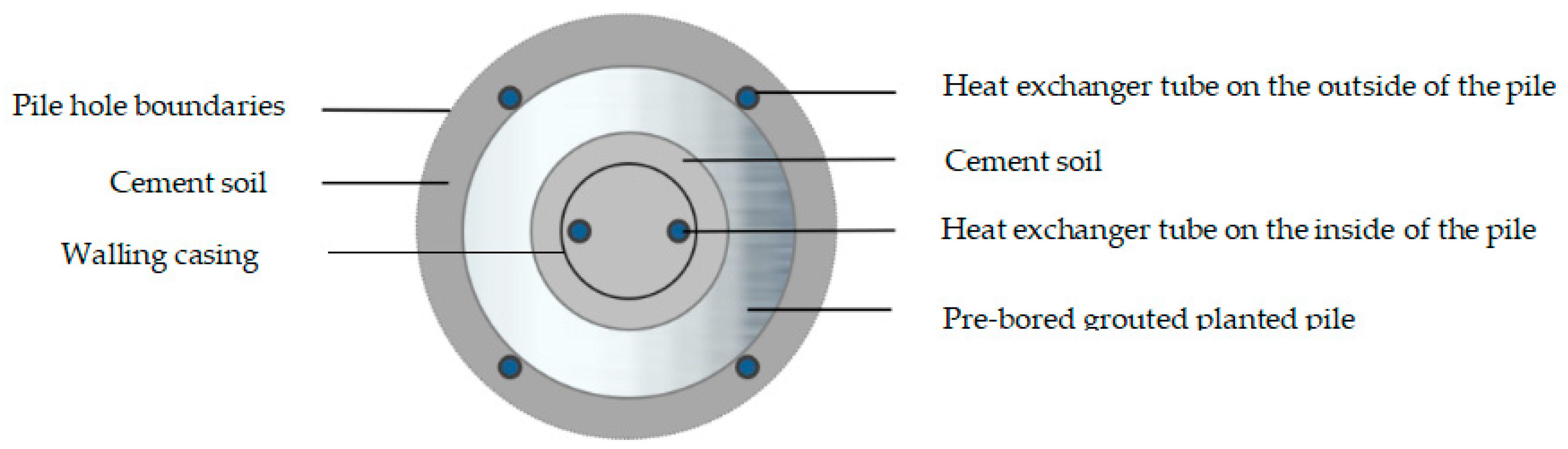
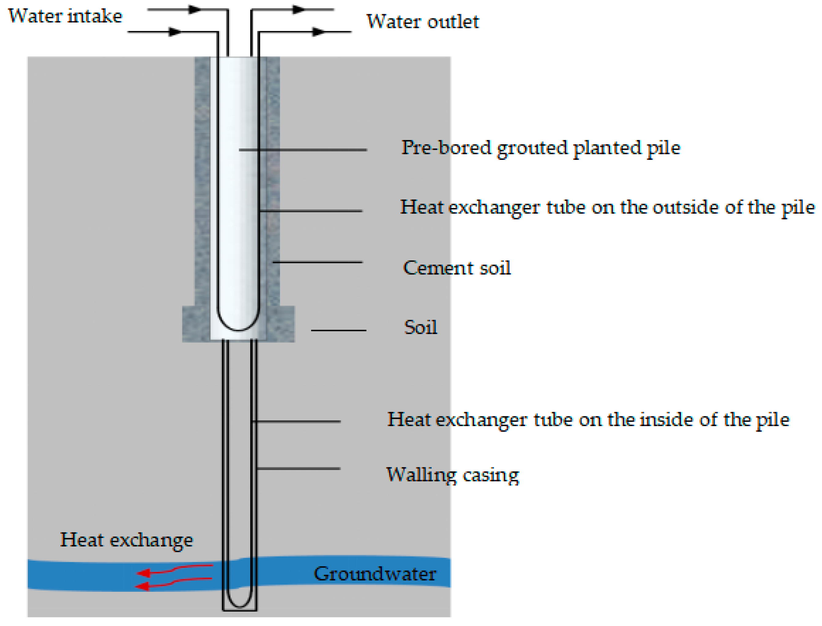
2. Technical Introduction

Studies have found that the longer the length of the energy pile, the better the heat transfer performance [13,24]. However, the length of the pile foundation is limited by economic constraints, construction progress, and other factors and cannot be too long. Considering the above situation, a new technology based on the combination of the pre-bored grouted planted energy pile and bored buried pipe ground source heat pump, i.e., deep and shallow combined buried pipe energy pile, is proposed: after the completion of the pre-bored grouted planted energy pile, a ground source heat pump system is laid in the hollow part of the precast pipe pile, and the U-tube heat exchanger of the ground source heat pump is buried 70–100 m below the surface or through the soil layer containing groundwater [5]. Figure 1 is a schematic diagram of the work of the deep and shallow combined buried pipe energy pile.
The deep and shallow combined buried energy pile installations all include heat exchanger tubes, hoses, and water circulation heat exchange systems. The top view of the deep and shallow combined buried energy piles is shown in Figure 2.
The deep and shallow combined buried energy pile represents an advancement in the pre-bored grouted planted energy pile techniques. The process commences with a drilling machine creating a hole, followed by an expansion of the bottom of the hole based on the predetermined diameter and height. Then, cement slurry is injected as the drill is retracted. The piles are connected by welding, and the heat exchange tubes, positioned externally on the piles, are symmetrically affixed to both the pile sides. The precast pipe piles are inserted into the cemented soil, predominantly depending on their inherent weight. Subsequently, an additional hole is drilled within the hollow section of the precast pipe pile to the designated depth, after which an inner heat exchange pipe is introduced. Accounting for geological conditions and economic factors, the advocated burial depth of the inner heat exchange pipe ranges between 70–100 m. This heat exchange pipe is connected with the water circulation heat exchange system via a hose, forming two distinct sets of heat exchange systems inside and outside the pile.
Therefore, the deep–shallow combined buried pipe energy pile technology integrates pre-bored grouted plant energy piles with borehole buried pipe ground source heat pumps. Incorporating these two heat exchange tube types produces savings in drilling and soil processing costs previously associated with the static drilling energy pile. This system capitalizes on the construction attributes of the static drilling energy pile as it optimizes the groundwater conditions in the coastal soft soil regions. For instance, in the Ningbo region, the soil stratum with optimal groundwater flow resides at depths of 60–70 m. The elongated heat exchange pipe traverses this groundwater area, as illustrated in Figure 3.
By leveraging the unique construction features of static drilling and planting piles, this combined buried energy pile offers distinct advantages over conventional energy piles. In particular, the peripheral region of the static drilling and planting pile is composed of a cement-soil slurry circle that simplifies the placement of the external U-shaped heat exchange pipe on the outside of the precast pile but also minimizes resistance during the pile sinking. Additionally, the center of the static drilling and planting pile, which is a precast pipe filled with cement-soil slurry, is conducive for placing the inner U-shaped heat exchange pipe. This internal U-shaped pipe can achieve significant depths, optimizing the groundwater conditions in coastal soft soil regions for heat exchange with deep groundwater, thereby delivering a superior heat exchange capacity.
This paper first presents the deep–shallow combined buried pipe energy pile, elucidating the rationale behind the development of this novel energy pile. Concurrently, it differentiates between static drilling root-embedded energy piles and deep-buried pipe energy piles. The subsequent sections explain the comprehensive procedures and methodologies for numerical simulation of this innovative energy pile, including aspects such as model creation, discretization techniques, equation resolution, and outcome interpretation. Thereafter, the results from the numerical simulations are discussed in-depth in the Section 4. Finally, the findings and contributions of this research are summarized in the Section 5.

3. Model Overview

3.1. Basic Assumptions

Energy pile operation is a complex 3D unsteady heat transfer process [23] that requires the following assumptions:
(1)
The operation of energy piles is a complex 3D unsteady state transmission, regardless of the influence of surface temperature changes on the temperature of the soil and pile body. The influence of liquid flow in the heating tube on the temperature distribution as well as the influence of temperature changes on the mechanical properties of the contact interface is not considered.
(2)
Precast piles, cement soil, heat exchanger tubes, and soil are homogeneous, their thermophysical properties and mechanical parameters do not change with temperature changes during operation, and heat is transferred between each part by heat conduction.
(3)
The initial temperature of the soil and pile body is consistent, and the heat exchanger tubes act as a stable heat source to transfer heat to the surroundings.
(4)
Groundwater-bearing soil layers are filled with groundwater, and the speed of the water flow does not change during the flow, regardless of its change along the direction of depth.
(5)
The pile body and cement soil are always in the elastic deformation range during the loading process, the friction coefficient between cement soil and soil remains unchanged, and the soil around the pile is elastoplastically deformed.

3.2. Model Building

The 3D finite element model of Abaqus was established. Sani et al. [25,26] believed that the temperature influence radii of different types of foundation soils such as sand and clay were 6 m and 4 m, respectively. In addition, Ma et al. [27] found that, in the numerical model, when the net distance between the lower boundary of the foundation and the bottom of the energy pile is greater than 10 m, the influence of the setting of the bottom boundary condition on the temperature change of the entire foundation is negligible, to a certain extent. The pile foundation is a precast pipe pile with a length of 40 m and 100 mm thick cement soil on the outside of the pile; therefore, the height of the soil layer model is 100 m (2.5 times the length of the precast pile). The energy pile is planted in the middle of the model, and the soil layer is 25 times the pile diameter to form a 3D model of 20 m × 20 m × 100 m (the boundary exceeds the radius of influence of soil temperature). The soil layer is simplified into three layers: the upper 40 m is clay, the lower 60 m is sand, and there is a flowing groundwater seepage at a depth of 65–70 m.
The elastic constitutive model is adopted for precast piles, the heat exchange tube, and water, and the Mohr–Coulomb elastoplastic model is adopted for cement soil and pile circumferential soil, which does not consider the influence of heat transfer liquid flow in the heat exchanger tubes on the temperature distribution. Studies have shown that precast piles work together with cement during loading, so they can be considered as a whole [28]. The initial temperature of the soil, groundwater, and cement soil was set to 20 °C. The Mohr–Coulomb friction penalty function was used to control the contact of the cement-soil interface, the contact relationship was the master-slave contact, the side of the cement soil was the main control surface, the soil body was the subordinate surface, and the friction coefficient was 0.3. For the displacement boundary, the bottom of the model foundation was fixed while the top of the model was free, and the normal deformations surrounding the periphery of the model were constrained. For the temperature boundary, the periphery and bottom of the model were set as the thermal insulating boundary.
The finite element mesh is divided based on experience, and a trial calculation is performed. Then the calculation results are compared against the results by both finer and coarser grid divisions. The grid division is depicted in Figure 4, wherein the depth dimensions of the soil, pile, and cement soil were set as 2 m, and the element size of the pile shaft and cement soil section was 0.1 m. Finally, 11,028 soil units, 960 pile units, and 2640 cement-soil units were considered for the simulation. For the heat exchange tube, the depth dimension was 0.2 m and its cross–section dimension was 0.01 m. Moreover, 6400 units were considered for the two 40 m long heat exchange tubes. For the coupled heat flow analysis, the DC3D8 and FC3D8 grid attributes were employed in the heat transfer model and the water flow, respectively.
The heat exchanger tubes are simplified to the column heat source in the 3D model, heat exchanger tubes material PE100 and heat exchanger tubes model DN38. The outer diameter of the heat exchanger tubes is 38 mm, the wall thickness is 2.5 mm, the length of the heat exchanger tubes on the outside of the pile is the same as the length of the pile, and the heat exchanger tubes are located on the inner side of the pile. The precast pile is composed of C80 concrete. The specific model material parameters are shown in Table 1.

3.3. Simulation Scenario

The analysis of energy pile involves multi-physical field coupling analysis of pile, soil, and fluid. The governing equations mainly include static equilibrium equation, stress–strain constitutive equation considering temperature effect, energy conservation equation of fluid in heat exchange tube, energy conservation equation of energy pile–soil system and Navier-Stokes equation [29,30,31]. In the simulation, the heat transfer process of energy pile–soil system is established first, and then the coupling analysis of thermo–fluid–solid is carried out. Lastly, temperature, stress and deformation are analyzed by numerical simulation results.
(1)
To understand the influence of groundwater seepage rate on the deep and shallow combined buried pipe energy pile, test groundwater inflow velocities were set at the inlet and outlet through boundary conditions at the load interface: 0, 2 × 10⁻⁶ m/s, 2 × 10⁻⁵ m/s and 2 × 10⁻⁴ m/s.
(2)
To understand the changes in the pile body under summer and winter conditions, the temperature of the heat exchanger tubes in the summer condition is set to 50 pile, test groundwater inflow velocities were 5 °C [10].
(3)
It is found that the longer the length of the energy pile, the better the heat transfer performance [22,24], but the effect of the length of the heat exchanger tubes on the inside of the pile on the pile body is unknown. Therefore, the length of the heat exchanger tubes on the inner side of the pile is 0 m, 40 m, 60 m, and 80 m, respectively.
There are 15 schemes, and the heat transfer time of each scheme is set to 10 days. The specific simulation test scheme is shown in Table 2.

4. Analysis of the Results

4.1. Pile Information

The pile top load–settlement curve under three working conditions, heating, normal temperature, and cooling, is obtained by numerical simulation, as shown in Figure 5, and 5000 kN is taken as the ultimate load value of PHC600 (130) according to the specifications [32]. In order to analyze the thermal–water–mechanical coupling effect of the long-term monitoring process of piles, the load level of the pile top is chosen as 50% of the ultimate load value of PHC600 (130). When the load is 1500 kN, the pile top settlement under the heating, normal temperature, and cooling conditions is 5.40 mm, 10.29 mm, and 12.89 mm, respectively. Under load-heating, the pile top settlement decreased by 47.52%. Under load-cooling, the pile top settlement increased by 25.27%. When the load is 2500 kN, the pile top settlement under the heating, normal temperature, and cooling conditions is 12.00 mm, 17.43 mm, and 20.35 mm, respectively. Under load-heating, pile top settlement decreased by 31.15%. Under load-cooling, the pile top settlement increased by 16.75%. When the load is 4000 kN, the pile top settlement under the heating, normal temperature, and cooling conditions is 23.26 mm, 29.31 mm, and 32.60 mm, respectively. Under load-heating, pile top settlement decreased by 20.64%. Under load-cooling, the pile top settlement increased by 11.22%. This is because the increase in temperature expands the pile body, thereby reducing the settlement of the pile top; the temperature drop causes the pile shaft to contract, which strengthened the settlement at the pile top. The influence of the surface settlement temperature gradually diminished with the increasing load amount. Additionally, the influence of the coupling effect of temperature and force on the settlement of the pile top could be related to the boundary condition, soil layer, and the construction method.

4.2. Temperature of the Pile Body and the Cement Soil Inside the Pile

Figure 6 shows the temperature variation curve of the pile body and cement soil in the pile with depth under different heat exchanger tube length combinations (L1 is the length of the outer heat exchanger tubes of the pile and L2 is the length of the inner heat exchanger tubes of the pile). It can be seen from Figure 6a that the temperature of the pile body decreased with the increase in depth under the heating condition. Under the cooling condition, the temperature of the pile body increased with the increase in depth. And in the case of rising and lowering temperature, the temperature of the pile end changed abruptly. After 10 days of warming process, when L2 = 0, 40, 60, and 80 m, the pile body changed by 18.35 °C, 20.97 °C, 19.61 °C, and 18.84 °C, respectively, compared with the initial average temperature. Compared with L2 = 0 m, when L2 = 40, 60, and 80 m, the pile temperature increased by 14.28%, 6.87%, and 2.67%, respectively. When L2 = 40 m, the increased heat exchange between the heat exchanger tubes and the pile body was 5.34 times that of L2 = 80 m and 2.08 times that of L2 = 60 m. After 10 days of the cooling process, when L2 = 0, 40, 60, and 80 m, the pile body changed by −7.77 °C, −9.09 °C, −8.77 °C, and −8.58 °C, respectively, compared with the initial average temperature. Compared with L2 = 0 m, when L2 = 40, 60, and 80 m, the pile temperature decreased by 17.00%, 12.87%, and 10.42%, respectively. When L2 = 40 m, the additional heat exchange between the heat exchanger tubes and the pile body was 1.63 times that of L2 = 80 m and 1.32 times that of L2 = 60 m.
The temperature variation pattern of the cement soil within the pile depth range Figure 6b was consistent with the temperature variation pattern of the pile body exhibited in Figure 6a. After 10 days of warming process, when L2 = 0, 40, 60, and 80 m, the cement soil in the pile changed by 18.30 °C, 24.49 °C, 22.02 °C, and 20.66 °C, respectively, compared with the initial average temperature. When this was compared with the pile temperature in the same situation, it was found that the temperature changed by −0.05 °C, 5.53 °C, 2.41 °C, and 1.82 °C, respectively. When the inner heat exchanger tubes of the pile were not laid, the average temperature difference between the cement soil in the pipe pile and the pile body was almost nothing, and after the inner heat exchanger tubes of the pile were laid, the temperature difference between the two was relatively obvious. With the increase of the length of the heat exchanger tubes on the inside of the pile, the temperature difference between the two gradually decreased from 5.53 °C to 1.82 °C. After 10 days of cooling process, when L2 = 0, 40, 60, and 80 m, the cement soil in the pile changed by −7.73 °C, −10.00 °C, −9.43 °C, and −9.09 °C, respectively, compared with the initial average temperature. When this was compared with the pile temperature in the same situation, it was found that the temperature changed by 0.04 °C, −0.91 °C, −0.66 °C, and −0.51 °C, respectively. In the scenario where heat exchange pipes were arranged inside the pile, significant variations in temperature were observed in the cement soil located below the pile’s depth range. After a 10-day heating process, the average temperature of the cement soil at L2 = 80 m was 30.3 °C. At L2 = 60 m, the average temperature of the cement soil was 32.8 °C. After a 10-day cooling process, the average temperature of the cement soil at L2 = 80 m was 14.9 °C. At L2 = 60 m, the average temperature of the cement soil was 13.9 °C. The results revealed that a greater amount of heat exchange occurred between the heat exchange tube and the soil at L2 = 80 m.
Since the length of the heat exchanger tubes on the outside of the pile is 40 m, the same length as the pile, the heat exchange between the heat exchanger tubes and the pile body at the pile end position will be significantly reduced, so the pile end temperature will have a sudden change in the same direction along the depth change trend. From the above data, it can be seen that, after adding the heat exchanger tubes on the inside of the pile, the temperature of the pile body changed significantly, but with the increase of the embedding depth of the heat exchanger tubes, the change of the temperature of the pile body gradually decreased. This is because, after the addition of the heat exchanger tubes on the inside of the pile, the heat exchange between the pile body and the heat exchanger tubes increased significantly, but with the increase of the length of the heat exchanger tubes on the inside of the pile, the heat exchanger tubes and the soil below the pile carried out more heat exchange, so the temperature difference between the heat exchange liquid and the pile body in the heat exchanger tubes decreased, leading to the decrease of the change of the temperature of the pile body and cement soil. When the inner heat exchanger tubes of the pile were not laid, the average temperature difference between the cement soil in the pipe pile and the pile body was almost negligible, and after the inner heat exchanger tubes of the pile were laid, the temperature difference between the two was relatively obvious, and with the increase of the length of the heat exchanger tubes on the inside of the pile, the temperature difference between the two gradually decreased from −0.91 °C to −0.51 °C. This is because, as the length of the heat exchanger tubes inside the pile increases, the heat exchange between the heat exchanger tubes and the surrounding soil body increases significantly. However, this also leads to a decrease in the heat exchange between the heat exchanger tubes and the cement soil. The temperature of the cement soil below the pile depth range was significantly lower than that of the cement soil within the pile depth range. This phenomenon occurred because the temperature of the heat exchange tube gradually decreased as it penetrated deeper into the soil, resulting in a gradual reduction in the temperature deviation between the heat exchange tube and the soil. In particular, the temperature of the cement soil experienced a significant variation at 40 m, which was consistent with the abrupt variation in the pile temperature at this depth.
Figure 7 shows the temperature change curve of the pile body and cement soil in the pile with depth under different groundwater flow velocities (v is the groundwater seepage flow rate). From Figure 7a, it can be seen that the temperature of the pile body decreased with the increase in depth, and the temperature changed suddenly when reaching the pile end. Under the warming conditions, with the gradual increase of groundwater seepage flow rate, the pile body temperature also gradually decreased, and the average change temperature of the pile body was 20.53 °C, 20.47 °C, 20.41 °C, and 18.84 °C in the environment of 0 m/s, 2 × 10⁻⁶ m/s, 2 × 10⁻⁵ m/s, and 2 × 10⁻⁴ m/s, respectively. When the groundwater flow rate increased from 0 m/s to 2 × 10⁻⁵ m/s, the pile temperature did not change significantly, but when the flow rate reached 2 × 10⁻⁴ m/s, the pile temperature change decreased by 11.91%. Under the cooling conditions, with the gradual increase of groundwater seepage flow rate, the pile body temperature also gradually increased, and the average change temperature of the pile body was −9.41 °C, −9.38 °C, −9.37 °C, and −8.58 °C in the environment of 0 m/s, 2 × 10⁻⁶ m/s, 2 × 10⁻⁵ m/s, and 2 × 10⁻⁴ m/s, respectively. When the groundwater flow rate increased from 0 m/s to 2 × 10⁻⁵ m/s, the pile temperature did not change significantly, but when the flow rate reached 2 × 10⁻⁴ m/s, the pile temperature change decreased by 8.82%.
The temperature variation pattern of the cement soil within the pile depth range displayed in Figure 7b is consistent with that of the pile body depicted in Figure 7a. Under the same warming load, when the groundwater seepage was at four different flow velocities, 0 m/s, 2 × 10⁻⁶ m/s, 2 × 10⁻⁵ m/s, and 2 × 10⁻⁴ m/s, the average change temperature of cement soil in the pile was 23.67 °C, 23.56 °C, 23.45 °C, and 20.66 °C, respectively. When the groundwater flow rate increased from 0 m/s to 2 × 10⁻⁵ m/s, the temperature of cement soil in the pile did not change significantly, but when the flow rate reached 2 × 10⁻⁴ m/s, the temperature change of cement soil in the pile decreased by 12.63%. Under the same cooling load, when the groundwater seepage was at four different flow velocities, 0 m/s, 2 × 10⁻⁶ m/s, 2 × 10⁻⁵ m/s, and 2 × 10⁻⁴ m/s, the average change temperature of cement soil in the pile was −10.53 °C, −10.48 °C, −10.45 °C, and −9.09 °C, respectively. When the groundwater flow rate increased from 0 m/s to 2 × 10⁻⁵ m/s, the temperature of cement soil in the pile did not change significantly, but when the flow rate reached 2 × 10⁻⁴ m/s, the temperature change of cement soil in the pile decreased by 13.68%. Notably, the temperature variation of the cement soil below the pile depth range was consistent with that within the pile depth range. When the groundwater seepage velocity was 2 × 10⁻⁴ m/s, the temperature variation curve exhibited a more pronounced slope compared to the curves for the other three velocities. This is a manifestation of the increased heat exchange with the groundwater seepage velocity.
Since the length of the heat exchanger tubes on the outside of the pile is 40 m, the same length as the pile, the heat exchange between the heat exchanger tubes and the pile body at the pile end position will be significantly reduced, so the pile end temperature will have a sudden change in the same direction along the depth change trend. With the increase of groundwater seepage velocity, the heat exchange between the heat exchange fluid and groundwater seepage in the heat exchanger tubes also gradually increases, so the temperature difference between the heat exchange fluid on the outlet side of the heat exchanger tubes and the pile body and cement soil decreases. This means that the heat exchange between the heat exchanger fluid in the heat exchanger tubes and the pile body and the cement soil is reduced, and the temperature change of the pile body and the cement soil is reduced. When the groundwater flow rate increased from 0 m/s to 2 × 10⁻⁵ m/s, the temperature of the pile body and cement soil did not change significantly because the heat exchange between the heat exchanger tubes and the groundwater seepage increased less in the flow rate range, but when the flow rate reached 2 × 10⁻⁴ m/s, the temperature of the pile body and cement soil changed significantly because the heat exchange between the heat exchanger tubes and the groundwater seepage increased significantly at this flow rate.
Figure 8 shows the temperature change cloud of the pile roof, from which it can be seen that the temperature of the pile soil under the condition of the inner heat exchanger tubes of the pile was significantly higher than that of the pile soil under the condition of the heat exchanger tubes on the outside of the pile. The range of the heat exchange impact is 2 m (3–4 times the pile diameter) from the center of the pile. Under the heating condition of 50 °C, the temperature of the outlet of the heat exchanger tubes on the outside of the pile was 45.50 °C, but the temperature of the outlet of the heat exchanger tubes on the inner side of the pile gradually decreased with the increase of depth, which was 42.06 °C, 38.56 °C, and 34.22 °C, respectively. Compared with the situation where the heat exchanger tubes on the inside of the pile were not arranged, the total heat exchange between the heat exchange fluid and the pile body and the soil in the heat exchanger tubes increased by 88.22%, 127.11%, and 133%. This is because, with the increase of the depth of the heat exchanger tubes on the inside of the pile, although the heat exchange between the heat exchanger tubes and the pile body is not obvious, the heat exchange between the heat exchanger tubes and the soil increased significantly.

4.3. Pile Top Displacement

Figure 9 shows the change curve of pile top displacement under different heat exchanger tube length combinations (L1 is the length of the outer heat exchanger tubes of the pile and L2 is the length of the heat exchanger tubes inside the pile). It can be seen from the figure that the top displacement of the pile is greatly affected by the temperature in the first four days, showing a rapid increase trend, and flattens after four days. After adding the heat exchanger tubes on the inside of the pile, the heat exchanger tubes and the pile body exchange more heat than the traditional energy pile, which only arranges the heat exchanger tubes on the outside of the pile. With the increase of the length of the heat exchanger tubes on the inside of the pile, more heat exchange between the heat exchanger tubes and the deep soil is carried out, and the heat exchange with the pile body gradually decreases. Under a load of 2500 kN and a temperature load of 50 °C, the maximum displacements caused by L2 = 40, 60, 80, and 0 m were 4.73 mm, 4.46 mm, 4.31 mm, and 4.07 mm, respectively. Compared with the settlement generated by the piles with only the pile top load, the settlement decreased by 27.63%, 26.05%, 25.18%, and 23.77%, respectively. This is due to the continuous reduction of heat exchange between the pile body and the heat exchanger tubes so that the expansion of the pile also constantly decreases. Under the load of 2500 kN and the temperature load of 5 °C, the maximum displacement caused by L2 = 40, 60, 80, and 0 m was −2.82 mm, −2.73 mm, −2.68 mm, and −2.41 mm, respectively. Compared with the settlement generated by the piles with only the pile top load, the settlement decreased by 16.47%, 15.95%, 15.65%, and 14.08%, respectively. This is due to the continuous decrease in heat exchange between the heat exchanger tubes and the surrounding soil, which leads to a constant reduction in the settlement of the pile.
Figure 10 shows the influence curve of groundwater seepage rate on pile top displacement (v is groundwater seepage flow rate), and it can be clearly seen that when the flow rate increased from 0 m/s to 2 × 10⁻⁵ m/s, the pile top displacement change in the temperature lifting condition was very small. The maximum displacement under the heating condition was 4.68 mm, 4.65 mm, and 4.64 mm, respectively, which decreased by 27.33%, 27.16%, and 27.10% compared with the settlement generated only under load. However, when the groundwater seepage rate reached 2 × 10⁻⁴ m/s, the pile top displacement changed greatly, and the maximum displacement was reduced to 4.31 mm, which is 25.18% less than the settlement generated only under load. It can be clearly seen that, when the flow rate increased from 0 m/s to 2 × 10⁻⁵ m/s, the maximum displacement under the cooling condition was −2.94 mm, −2.92 mm, and −2.91 mm, respectively, which increased by 17.17%, 17.06%, and 17.00% compared with the settlement generated only under load. However, when the groundwater seepage velocity reached 2 × 10⁻⁴ m/s, the top displacement of the pile had a clear change, and the maximum displacement was reduced to −2.68 mm, which is reduced by 15.65% compared with the settlement generated only under loading. This is due to the fact that, in the case of a low flow rate, the heat taken away by the heat exchange liquid in the heat exchanger tubes does not increase significantly, but when the flow rate reaches 2 × 10⁻⁴ m/s, the heat taken away by groundwater seepage exceeds a critical point, which has a greater impact on the temperature of the pile body and significantly reduces the expansion of the pile.

4.4. Pile Axial Force

Figure 11 shows the distribution curve of the axial force of the pile body under different combinations of heat exchanger tube lengths (L1 is the length of the outer heat exchanger tubes of the pile and L2 is the length of the inner heat exchanger tubes of the pile). The PHC600 (130) had a pile top axial force of 2493 kN only under a 50% ultimate load (shown by the black line in Figure 11), and the pile shaft force gradually decreased to 47 kN with increasing depth. When it was heated by the heat exchanger tubes on the outside of the pile and with 50% ultimate load (shown by the red line in Figure 11), the pile top axial force was 2513 kN, and the pile shaft force gradually decreased to 139 kN with increasing depth. At this time, compared with the situation where the heating load was not applied, the axial force of the pile top was increased by 0.80%, and the axial force of the pile end was increased by a factor of three. When the heat exchanger tubes on the inside of the pile were laid, the axial forces of the pile top were 2527, 2522, and 2519 kN in the three cases of L2 = 40, 60, and 80 m, respectively, which increased by 1.36%, 1.16%, and 1.04% compared with the situation without applying heating load. The axial forces of the pile end were 170, 169, and 160 kN, respectively, which increased by a factor of 3.6, 3.6, and 3.4 compared with the situation without applied heating load. It can be seen from the figure that, after the application of heating load, the axial force of the pile body increased significantly, especially in the lower part of the pile, and the axial force of the pile body reached the maximum increase in the middle and lower part of the pile, which was 469, 433, and 413 kN, respectively, accounting for 48.57%, 44.83%, and 42.80% of the axial force of the pile body when the temperature load was not applied. When the outer heat exchanger tubes were cooled and subjected to a 50% ultimate load (shown by the yellow line in Figure 10), the pile top axial force was 2491 kN, and the pile shaft force gradually decreased to 23 kN with increasing depth. Compared with the situation without the application of a cooling load, the axial force of the pile top was reduced by 0.08%, and the axial force of the pile end was reduced by 51.06%. When the heat exchanger tubes on the inside of the pile were laid, the axial forces of the pile top were 2486, 2487, and 2488 kN in the three cases of L2 = 40, 60, and 80 m, respectively, which were reduced by 0.28%, 0.24%, and 0.20% compared with the situation without applying cooling load. The axial forces of the pile end were 10, 9, and 6 kN, respectively, and the axial forces of the pile end were reduced by 78.72%, 80.85%, and 87.23% compared with the situation without cooling load. When the cooling load was applied, it can be seen that the axial force of the pile body decreased, and the axial force of the pile body reached the maximum reduction in the middle and lower part of the pile, which was 115, 109, and 106 kN, respectively, accounting for 24.50%, 23.31%, and 22.59% of the axial force of the pile body without the applied temperature load. As the length of the heat exchanger tubes on the inside of the pile increased, the heat transfer between the heat exchanger tubes and the surrounding soil increased; that is, the temperature of the pile body changed less at the end of the heat exchange. Therefore, the temperature stress caused by temperature changes also decreased, and the changes in the axial force between the pile end and the pile top also decreased.
Figure 12 shows the distribution curve of the axial force of the pile body under different groundwater seepage flow rates (v is the groundwater seepage flow rate). Under the warming condition, when the groundwater seepage flow rate was 0 m/s, the axial force of the pile body decreased from 2524.8 to 181.7 kN with the increase of depth, and the axial force of the pile body gradually decreased with the increase of groundwater seepage flow rate. When the seepage velocity of groundwater was 2 × 10⁻⁶ m/s and 2 × 10⁻⁵ m/s, the pile top axial forces were 2524.3 and 2524.0 kN, respectively, and the pile end axial forces were 181.4 and 180.6 kN, respectively; the pile top axial force and pile end axial force remained almost unchanged. However, when the groundwater seepage rate increased to 2 × 10⁻⁴ m/s, the axial force of the pile top decreased to 2519.4 kN, and the axial force of the pile end was also reduced to 160.1 kN. Compared with the flow rate of 0 m/s, the axial force of the pile top was reduced by 0.21%. The axial force of the pile end was reduced by 11.89%, and the axial force of the pile body was also relatively significantly reduced compared with the previous low flow rate. Under the cooling condition, when the groundwater seepage flow rate was 0 m/s, the axial force of the pile body decreased from 2485.3 to 2.0 kN with the increase of depth, and the axial force of the pile body gradually decreased with the increase of groundwater seepage flow rate. When the flow rate was 2 × 10⁻⁶ m/s and 2 × 10⁻⁵ m/s, the pile top axial forces were 2485.4 and 2486.1 kN, respectively, and the pile end axial forces were 2.4 and 2.5 kN, respectively; the pile top axial force and pile end axial force remained almost unchanged. However, when the flow rate increased to 2 × 10⁻⁴ m/s, the axial force of the pile top increased to 2487.2 kN, and the axial force of the pile end also increased to 8.9 kN. Compared with the flow rate of 0 m/s, the axial force of the pile top increased by 0.07%. The axial force of the pile end increased by a factor of 4.45, and the axial force of the pile body also increased relatively significantly compared with the previous low flow rate. In this study, the pile axial forces compared between the heating/cooling and normal temperature conditions was consistent with prior research findings [33].

4.5. Pile Side Friction Resistance

Figure 13 shows the distribution curve of pile friction resistance under different heat exchanger tube length combinations (L1 is the length of the outer heat exchanger tubes of the pile and L2 is the length of the inner heat exchanger tubes of the pile). It can be seen that, under the combination of heat exchanger tubes of different lengths, the trend of friction resistance on the side of the pile is basically the same, and the pile body does not produce negative friction resistance. Due to the load on the top of the pile, the neutral point is moved up to the vicinity of the top of the pile. With the increase of depth, the friction resistance of the pile side gradually increases, and gradually decreases after reaching the peak. This is because the temperature change produces the side friction resistance, but the negative friction resistance value caused by heating is less than the positive friction resistance generated under the load, so it is all positive after superposition, and the original positive friction resistance becomes larger, the part close to the bottom of the pile becomes smaller, and the side friction resistance decreases due to the reaction force of the deeper soil layer. Under the action of heating load, the lateral friction resistance of the upper part of the pile body decreases, resulting in a pull-down load on the pile body, which significantly increases the axial force of the lower part of the pile body, and the axial force increase in the lower part of the pile body can reach about 1.5 times the value. Under the action of cooling load, the increase of lateral friction resistance in the upper part of the pile body and the decrease in the axial force of the lower section of the pile body are obvious.
Under the combined action of the heating load and the pile top load of 2500 kN, the difference between the side friction resistance at L2 = 40 m and the side friction resistance at L2 = 0 m was −2.3–3.4 kPa; the difference between the side friction resistance at L2 = 60 m and the side friction resistance at L2 = 0 m was −1.2–3 kPa; and the difference between the side friction resistance at L2 = 80 m and the side friction resistance at L2 = 0 m was −0.9–2.6 kPa. Under the combined action of cooling load and pile top load of 2500 kN, the difference between the side friction resistance at L2 = 40 m and the side friction resistance at L2 = 0 m was −0.6–1.3 kPa; the difference between the side friction resistance at L2 = 60 m and the side friction resistance at L2 = 0 m was −0.4–1.0 kPa; and the difference between the side friction resistance at L2 = 80 m and the side friction resistance at L2 = 0 m was −0.3–0.7 kPa. It can be seen that, under the same load conditions, with the increase of the length of the heat exchanger tubes on the inside of the pile, the increasing effect of temperature change on the positive friction resistance of the precast pipe pile is greater than the decreasing effect and that, with the decrease of the length of the heat exchanger tubes inside the pile, the amplitude of the increase and decrease of the two increases further.
Figure 14 shows the distribution curve of pile side friction resistance under different groundwater seepage flow rates (v is the groundwater seepage flow rate). Under the combined action of the heating load and the pile top load of 2500 kN, the difference between the side friction resistance at v = 2 × 10⁻⁶ m/s and the side friction resistance at v = 0 m/s was −0.2–0.1 kPa, the difference between the side friction resistance at v = 2 × 10⁻⁵ m/s and the side friction resistance at v = 0 m/s was −0.4–0.2 kPa, and the difference between the side friction resistance at v = 2 × 10⁻⁴ m/s and the side friction resistance at v = 0 m/s was −1.1–1.3 kPa. Under the combined action of cooling load and pile top load of 2500 kN, the difference between the side friction resistance at v = 2 × 10⁻⁶ m/s and the side friction resistance at v = 0 m/s was −0.1–0.1 kPa, the difference between the side friction resistance at v = 2 × 10⁻⁵ m/s and the side friction resistance at v = 0 m/s was −0.2–0.3 kPa, and the difference between the side friction resistance at v = 2 × 10⁻⁴ m/s and the side friction resistance at v = 0 m/s was −0.6–0.7 kPa. It can be seen that, under the same load conditions, the groundwater seepage flow rate increases, and the increasing effect of temperature rise and fall on the positive friction resistance of precast pipe piles is greater than the decreasing effect and that, with the increase of groundwater seepage flow rate, the amplitude of the increase and decrease of the two increases further. In this study, the pile lateral friction forces compared between the heating/cooling and normal temperature conditions are consistent with previous research findings [33].

5. Conclusions and Prospect

A new energy pile technology with the combination of long and short heat exchanger tubes is proposed for implementations in coastal areas. Numerical simulation was performed for a Ningbo rail transit project. The following main conclusions are gained:
(1)
The new energy pile technology considers the groundwater condition., which enhances the heat exchange between the tubes and the soil. It also helps to dissipate the heat from the soil, effectively addressing the issue of heat accumulation.
(2)
The temperature change of the cement soil in the pile is consistently higher than the temperature of the pile body by 1–2 °C. As the length of the heat exchanger tubes on the inside of the pile increases, the stable temperature change of both the pile body and the cement soil gradually decreases.
(3)
When there is groundwater flow, the temperature change of the pile gradually decreases with the acceleration of groundwater flow. The maximum temperature change can be reduced by 11.91% (1.69 °C) and 8.82% (0.83 °C) for cooling changes. Additionally, the pile body reaches a stable temperature become faster under groundwater flow condition; and the higher the flow rate is, the faster the stabilization will be reached.
(4)
Under the coupling effect of heat and force, the displacement is positively correlated with the temperature change. Although the arrangement of heat exchange tubes inside the pile increases the amount of heat exchange, the maximum changes in the uplift and settlement of the pile top only increase by 0.66 mm and 0.41 mm, respectively.
(5)
Under the action of thermal coupling, the expansion of the pile shaft results in a decrease in the lateral friction resistance of the upper section and an increase in the axial force of the lower section. The axial force change of the pile shaft is positively correlated with temperature change. The axial force change increases for the new energy pile, but the maximum change is only 61 kN and −19 kN for temperature heating or cooling condition, respectively.
(6)
Compared with L2 = 80 m, v = 2 × 10⁻⁴ m/s and L2 = 0 m, v = 2 × 10⁻⁴ m/s, the temperature difference of the average temperature of the pile body is within 1 °C; hence, after the heat exchanger tubes on the inside of the pile are laid, the axial force of the pile body and the displacement of the top of the pile are not obvious. The average temperature of the heat exchanger tubes on the outside of the pile and the outlet of the heat exchanger tubes on the inside of the pile are 45.50 °C and 34.22 °C, respectively, and the total heat exchange increases by a factor of 1.75.
(7)
This paper focuses on the effect of different tube types on heat exchange efficiency and the mechanical properties of pile and soil layers. The design of heat exchanger needs to consider many factors, such as building environment, energy demand, geological conditions, structural design, etc., which is worthy of further study. In addition, comparative studies that include theoretical analyses, numerical simulations, and field measurements are needed to further promote the application of the new energy pile technology.

Author Contributions

Conceptualization, S.C. and Y.D.; methodology, Y.D.; software, S.C. and S.N.; validation, Y.D. and R.Z.; formal analysis, G.C.; investigation, S.N.; resources, R.Z.; data curation, S.C.; writing—original draft preparation, S.C. and S.N.; writing—review and editing, Y.D.; visualization, S.C.; supervision, W.M.; project administration, W.M.; funding acquisition, Y.D. and R.Z. All authors have read and agreed to the published version of the manuscript.

Funding

This research is the key project of Ningbo Natural Science Foundation of China (2023J004), and the development and demonstration of the complete technology of static drilling grounding geothermal energy pile in the field of road traffic (project no. 2022Z224).

Institutional Review Board Statement

Not applicable.

Informed Consent Statement

Not applicable.

Data Availability Statement

The data used to support the findings of this study are currently under embargo while the research findings are commercialized. Requests for data, 12 months after publication of this article, will be considered by the corresponding author.

Acknowledgments

Thanks to the key project of Natural Science Foundation of Ningbo (2023J004), the development and demonstration of complete technology of static drilling grounding geothermal energy pile in the field of road traffic (project no. 2022Z224).

Conflicts of Interest

Author Wei Ming and Rihong Zhang was employed by the company Ningbo Zhongchun Hi-Tech Co. The remaining authors declare that the research was conducted in the absence of any commercial or financial relationships that could be construed as a potential conflict of interest.

References

  1. Chen, Y.; Chen, Y. The theoretical implication and significance of Xi Jinping’s important discourse on tackling global climate change. Marx. Real. 2021, 6, 1–25+195. [Google Scholar]
  2. Go, G.-H.; Lee, S.-R.; Kang, H.-B.; Yoon, S.; Kim, M.-J. A novel hybrid design algorithm for spiral coil energy piles that considers groundwater advection. Appl. Therm. Eng. 2015, 78, 196–208. [Google Scholar] [CrossRef]
  3. Yang, W.; Qiang, Y.; Ju, L.; Wang, F.; Liu, A. Numerical evaluations on the effects of different factors on thermo- mechanical behaviour of an energy pile group. Comput. Geotech. 2023, 162, 105664. [Google Scholar] [CrossRef]
  4. Barbieri, S.; Antelmi, M.; Panday, S.; Baratto, M.; Angelotti, A.; Alberti, L. Innovative numerical procedure for simulating borehole heat exchangers operation and interpreting thermal response test through MODFLOW-USG code. J. Hydrol. 2022, 614, 128556. [Google Scholar] [CrossRef]
  5. Antelmi, M.; Turrin, F.; Zille, A.; Fedrizzi, R. A New Type in TRNSYS 18 for Simulation of Borehole Heat Exchangers Affected by Different Groundwater Flow Velocities. Energies 2023, 16, 1288. [Google Scholar] [CrossRef]
  6. Brandl, H. Energy foundations and other thermo-active ground structures. Géotechnique 2006, 56, 81–122. [Google Scholar] [CrossRef]
  7. Morino, K.; Oka, T. Study on heat exchanged in soil by circulating water in a steel pile. Energy Build. 1994, 21, 65–78. [Google Scholar] [CrossRef]
  8. Sung, C.; Park, S.; Lee, S.; Oh, K.; Choi, H. Thermo-mechanical behavior of cast-in-place energy piles. Energy 2018, 161, 920–938. [Google Scholar] [CrossRef]
  9. Park, S.; Lee, S.; Oh, K.; Kim, D.; Choi, H. Engineering chart for thermal performance of cast-in-place energy pile considering thermal resistance. Appl. Therm. Eng. 2018, 130, 899–921. [Google Scholar] [CrossRef]
  10. Li, F.Y.; Wang, Z.J.; Xie, X.Y.; Lou, Y.; Wang, K.H.; Fang, P.F.; Zheng, L.W. Model test on bearing characteristic of static drill rooted energy pile. Rock Soil Mech. 2020, 41, 3307–3316. [Google Scholar]
  11. Cao, G.; Deng, Y.; Yu, L.; Zhang, R. Model test of static drilling and rooted energy pileconsidering over-consolidated behavior of soft soil. J. Shenzhen Univ. (Sci. Technol. Ed.) 2022, 39, 93–100. [Google Scholar]
  12. Yoon, Y.; Hyeon, S.; Kim, D.R.; Lee, K.S. Minimizing thermal interference effects of multiple heat sources for effective cooling of power conversion electronics. Energy Convers. Manag. 2018, 174, 218–226. [Google Scholar] [CrossRef]
  13. Park, S.; Lee, S.; Lee, D.; Ahn, D.; Choi, H. Effect of thermal interference on energy piles considering various configurations of heat exchangers. Energy Build. 2019, 199, 381–401. [Google Scholar] [CrossRef]
  14. Suryatriyastuti, M.; Mroueh, H.; Burlon, S. A load transfer approach for studying the cyclic behavior of thermo-active piles. Comput. Geotech. 2014, 55, 378–391. [Google Scholar] [CrossRef]
  15. Lyu, W.; Pu, H.; Xiao, H.; Hu, D.; Ma, Q. Thermal performance of energy pile with deeply penetrating 1-U-shape heat exchanger. Geothermics 2021, 91, 102023. [Google Scholar] [CrossRef]
  16. Chen, Z.; Hei, D.; Zhang, G.; Xiao, H.; Wang, B. Experiment and simulation research on heat exchange of different types of underground heat exchangers. J. Shenzhen Univ. (Sci. Technol. Ed.) 2022, 39, 20–27. [Google Scholar] [CrossRef]
  17. Chen, Z.; Yao, J.; Pan, P.; Xiao, H.; Ma, Q. Research on the heat exchange characteristics of the deeply buried pipe type of energy pile. Case Stud. Therm. Eng. 2021, 27, 101268. [Google Scholar] [CrossRef]
  18. Wang, Z.J.; Fang, P.F.; Wang, K.H.; Zhang, R.H.; Li, F.Y. Interactions between energy piles caused by temperature. Geotech. Res. 2019, 6, 218–226. [Google Scholar] [CrossRef]
  19. Zhao, H.; Ma, L. Several rough set models in quotient space. CAAI Trans. Intell. Technol. 2022, 7, 69–80. [Google Scholar] [CrossRef]
  20. Jeong, S.; Lim, H.; Lee, J.K.; Kim, J. Thermally induced mechanical response of energy piles in axially loaded pile groups. Appl. Therm. Eng. 2014, 71, 608–615. [Google Scholar] [CrossRef]
  21. Han, C.; Yu, X. Analyses of the thermo-hydro-mechanical responses of energy pile subjected to non-isothermal heat exchange condition. Renew. Energy 2020, 157, 150–163. [Google Scholar] [CrossRef]
  22. You, S.; Cheng, X.; Yu, C.; Dang, Z. Effects of groundwater flow on the heat transfer performance of energy piles: Experimental and numerical analysis. Energy Build. 2017, 155, 249–259. [Google Scholar] [CrossRef]
  23. Lou, Y.; Fang, P.; Zhang, R.; Xie, X.; Wang, Z.; Lai, X.; He, G.; Zhao, S. Heat Transfer Performance Analysis of Static Drill Rooted Geothermal Energy Piles with External Double U-tubes. J. Disaster Prev. Mitig. Eng. 2021, 41, 100–109. [Google Scholar]
  24. Xu, X.; Shui, W.; Chen, G. Vertical bearing capacity of super-long bored Piles in soft soil area. Chin. J. Geotech. Eng. 2011, 33, 502–507. [Google Scholar]
  25. Sani, A.; Singeh, R. Response of unsaturated soils to heating of geothermal energy pile. Renew. Energy 2020, 147, 2618–2632. [Google Scholar] [CrossRef]
  26. Peron, H.; Knellwolf, C.; Laloui, L. A method for the geotechnical design of heat exchanger piles. Geotech. Spec. Publ. 2011, 470–479. [Google Scholar] [CrossRef]
  27. Ma, Q.; Wang, P. Underground solar energy storage via energy piles. Appl. Energy 2020, 261, 114361. [Google Scholar] [CrossRef]
  28. GB 50010-2010; Code for Design of Concrete Structures. China Architecture and Building Press: Beijing, China, 2010.
  29. Kiani, K.; Pakdaman, H. Nonlocal vibrations and potential instability of monolayers from double-walled carbon nanotubes subjected to temperature gradients. Int. J. Mech. Sci. 2018, 144, 576–599. [Google Scholar] [CrossRef]
  30. Kiani, K.; Wang, Q. Nonlocal magneto-thermo-vibro-elastic analysis of vertically aligned arrays of single-walled carbon nanotubes. Eur. J. Mech. A/Solids 2018, 72, 497–515. [Google Scholar] [CrossRef]
  31. She, G.L.; Yuan, F.G.; Ren, Y.R.; Liu, H.B.; Xiao, W.S. Nonlinear bending and vibration analysis of functionally graded porous tubes via a nonlocal strain gradient theory. Compos. Struct. 2018, 203, 614–623. [Google Scholar] [CrossRef]
  32. JGJ 106-2014; Technical Code for Testing of Building Foundation Piles. China Architecture and Building Press: Beijing, China, 2014.
  33. Jiang, G.; Li, R.F.; Wang, H.; Chen, G.; Lu, H.W.; Shao, D. Numerical analysis of the bearing capacity of floating energy piles during the full process of thermal-mechanical coupling. J. Rock Mech. Eng. 2019, 38, 2525–2534. [Google Scholar]
Figure 1. Schematic of deep–shallow combined buried pipe energy pile.
Applsci 13 12579 g001
Figure 2. Top view of deep–shallow combined buried pipe energy pile.
Applsci 13 12579 g002
Figure 3. Schematic diagram of single deep–shallow combined buried energy pile.
Applsci 13 12579 g003
Figure 4. Grid layout of the deep–shallow combined buried energy pile.
Applsci 13 12579 g004aApplsci 13 12579 g004b
Figure 5. Pile top load-settlement numerical simulation curve.
Applsci 13 12579 g005
Figure 6. Temperature change curve of pile body and pile cement soil with different heat exchanger tube lengths under the condition of 2 × 10⁻⁴ m/s flow rate. (a) Pile body temperature change curve with depth. (b) Change curve of cement-soil temperature with depth.
Applsci 13 12579 g006aApplsci 13 12579 g006b
Figure 7. Temperature change curve of pile and soil with different groundwater velocity. (a) Pile body temperature change curve with depth. (b) Change curve of cement-soil temperature with depth.
Applsci 13 12579 g007
Figure 8. Cloud diagram of pile top temperature change.
Applsci 13 12579 g008aApplsci 13 12579 g008b
Figure 9. Effect curve of heat exchanger tube length on the displacement of pile top under 2 × 10⁻⁴ m/s flow rate.
Applsci 13 12579 g009
Figure 10. Effect curve of groundwater seepage rate on pile top displacement.
Applsci 13 12579 g010
Figure 11. Effect curve of heat exchanger tube length on the axial force of pile under the condition of 2 × 10⁻⁴ m/s flow rate.
Applsci 13 12579 g011
Figure 12. Impact curve of groundwater seepage rate on the axial force of pile body.
Applsci 13 12579 g012
Figure 13. Effect curve of heat exchanger tube length on side friction resistance of pile under 2 × 10⁻⁴ m/s flow rate.
Applsci 13 12579 g013
Figure 14. Impact curve of groundwater seepage rate on lateral friction resistance of pile shaft.
Applsci 13 12579 g014
Table 1. Model material parameters.
MaterialThickness (m)γ (kN/m3)c (kPa)φ (°)µE (MPa)λ (W/mK)C (J/kgK)α
Clay401937.816.90.35251.2616705 × 10−6
Sandy soil6019.442.9170.3651.716205 × 10−6
Cement soil/20150450.251800.9610007 × 10−6
Precast piles/25//0.238,0001.7417061 × 10−5
Heat exchanger tubes/12//0.420000.482300/
Note: γ indicates severity; c represents cohesion; φ denotes internal friction angle; µ denotes the Poisson’s ratio; E refers to the elastic modulus; λ stands for thermal conductivity; C represents specific heat capacity; α indicates the thermal expansion coefficient.
Table 2. Simulation test scheme.
GroupGroundwater Seepage Rate (m/s)Heat Transfer Fluid Temperature (°C)Heat Exchanger Tube on the Outside of the Pile (m)Heat Exchanger Tube on the Inside of the Pile (m)
12 × 10−4/00
20504080
32 × 10−6504080
42 × 10−5504080
52 × 10−4504080
62 × 10−4504060
72 × 10−4504040
82 × 10−450400
9054080
102 × 10−654080
112 × 10−554080
122 × 10−454080
132 × 10−454060
142 × 10−454040
152 × 10−45400
Disclaimer/Publisher’s Note: The statements, opinions and data contained in all publications are solely those of the individual author(s) and contributor(s) and not of MDPI and/or the editor(s). MDPI and/or the editor(s) disclaim responsibility for any injury to people or property resulting from any ideas, methods, instructions or products referred to in the content.

