Article

Infiltration Grouting Mechanism of Bingham Fluids in Porous Media with Different Particle Size Distributions

1
School of Mining Engineering, Anhui University of Science and Technology, Huainan 232001, China
2
State Key Laboratory of Deep Geotechnics and Underground Engineering, China University of Mining and Technology, Xuzhou 221116, China
*
Author to whom correspondence should be addressed.
Appl. Sci. 2023, 13(21), 11986; https://doi.org/10.3390/app132111986
Submission received: 19 September 2023 / Revised: 28 October 2023 / Accepted: 30 October 2023 / Published: 2 November 2023
(This article belongs to the Special Issue Mechanics, Damage Properties and Impacts of Coal Mining)

Abstract

:
Although permeation grouting technology has been widely used in engineering practice, there has not been sufficient research on how the distribution of pore sizes in porous media affects the diffusion of grout. In this study, based on the fractal theory of porous media and the Bingham fluid rheological equation, a Bingham fluid permeation grouting mechanism considering the distribution of pore sizes in porous media is proposed. The mechanism is validated through laboratory experiments and numerical simulations using COMSOL 6.0. During the experiments, parallel electrical resistance imaging is employed to monitor the diffusion range of the grout. Furthermore, the effects of grouting pressure, porosity, and water–cement ratio on the diffusion radius of the grout are analyzed. The results show that the Bingham fluid grout diffuses in a semi-spherical shape in the gravel. Additionally, parallel electrical resistance imaging can analyze the diffusion range of the grout in the gravel. The diffusion radius of the Bingham fluid grout in the gravel is smaller than the diffusion radius obtained by considering the particle size distribution theory, with an average difference of 31.8%. Compared to the diffusion radius obtained without considering the particle size distribution theory, the diffusion radius obtained by considering the distribution of pore sizes is closer to the experimental results. The numerically simulated program, which was developed for this study, can effectively simulate the diffusion law of the Bingham fluid in the gravel. So far, the Bingham fluid seepage grouting model considering the different particle size distribution of porous media has been built. The findings of this study can provide theoretical support and technical reference for practical grouting projects.

1. Introductory

A gravelly soil is typically one that contains a substantial amount of gravel particles. Gravel itself consists of small, rounded or angular fragments of rock. The composition of gravel soils varies worldwide, but they consistently have a high proportion of gravel. Gravelly soils often form through geological processes such as weathering, glacial deposits, geological tectonics, and impact-related mineral deposits [1,2]. Gravelly soil, owing to its composition of soil and gravel particles, exhibits distinct characteristics including loose structural integrity, sizable interstitial spaces between particles, uneven spatial distribution, and low cohesive properties. Consequently, it is predisposed to precipitating a range of geological hazards, such as landslides, fluvial and coastal erosion, debris flows, and mining collapses, thereby resulting in significant detriment to human life and property [3,4]. In order to mitigate the losses caused by the engineering characteristics of gravelly soil, numerous scholars have conducted extensive research on gravel composition. Liu [5] elucidated the principal controlling factors for four distinct types of fracture propagation based on a comparative assessment of the hardness between the matrix and gravel. Li [6] investigated the impact of gravel content in gravelly soil on soil erosion and sediment transport. Xu [7] and their research team have examined the pivotal factors that affect the long-term durability of natural rock in engineering systems, which include the repeated freeze–thaw cycles and loading conditions. Rahmani [8] introduced an image-based technique for measuring the volume, weight, and size distribution of gravel particles in gravelly soil. Hubler [9] devised a novel porosity pressure model for forecasting superporosity pressure based on uniform coefficients applicable to gravelly soil. In summary, many scholars have conducted research on the physical-mechanical properties of gravelly soil. However, there has been relatively limited research on grouting reinforcement for gravelly soil.
Typically, gravel reinforcement is accomplished through permeation grouting. This technique was initially employed by French engineer Charles Birge during the restoration of the Dieppe sand gates. Due to its positive impact on enhancing gravel layer stability and its overall effectiveness, it has progressively gained wide acceptance within the geotechnical engineering field. Its applications span various domains, including mines, construction, highways, subways, and other engineering fields, yielding favorable engineering outcomes [10,11]. The earliest theory of permeation grouting diffusion, epitomized by Maag’s work, predominantly focused on Newtonian fluid-based permeation grouting. Subsequently, scholars have persistently worked on improving and refining permeation grouting techniques. Initially, these techniques were tailored for Newtonian fluids, suitable for shapes like spheres and columns. However, they are not applicable to non-Newtonian fluids, such as power-law and Bingham fluids. Yang [12,13] established a spherical infiltration-diffusion model for non-Newtonian fluids in homogeneous sandy soil based on the capillary model and the rheological characteristics of non-Newtonian fluids. Subsequently, Yang [14,15] conducted research on the columnar diffusion model of cement slurry within gravelly soil. In order to further investigate the factors influencing permeation grouting, Axelsson [16] studied the cessation mechanism of grout during the permeation grouting process at different water–cement ratios. Li [17] experimentally validated that vibration grouting can enhance the grouting efficiency. Weng [18] utilized low-field nuclear magnetic resonance (NMR) technology to investigate the diffusion behavior of slurry within fractured rock masses concerning temperature, confining pressure, flow rate, and the number of fractures. Wang [19] derived a semi-spherical diffusion model for Newtonian fluids considering the tortuosity of porous media and the time-dependent viscosity of the slurry. Escobal-Marcos [20] proposed a behavioral model to explain the heterogeneity observed in the radius of influence during injection. Zhu [21] conducted a study using Computational Fluid Dynamics and Discrete Element Method (CFD-DEM) to investigate the permeation of cement-based grout in porous media and the filtration behavior of cement particles. Farhangi [22], based on Cone Penetration Testing (CPT) and Standard Penetration Testing (SPT), provided confirmation of the effectiveness of micropile jet grouting in enhancing soil properties and mitigating liquefaction risk. Simultaneously, scholars have conducted research into the intricate flow of fluids in porous media. Zhang [23,24] proposed an adaptive deep learning algorithm that can quantitatively predict the total phase count of reservoir fluids in equilibrium under various environmental conditions.
In the reinforcement of gravelly formations, penetration grouting is commonly employed. Typically, readily available and cost-effective cement grout solutions are chosen for this purpose in engineering practice. Consequently, non-Newtonian fluids are frequently utilized for the consolidation of porous media formations. Simultaneously, numerous scholars have conducted research on non-Newtonian fluids in this context. Given the complexity of grouting geology, Yang [25] investigated the influence of the diffusion path of Bingham fluids within porous media on the diffusion behavior of the grout. Zou [26] studied the propagation of non-Newtonian fluids in various homogeneous or heterogeneous fracture networks. Lavrov [27] provided a comprehensive overview of non-Newtonian flow in fractures. Shamu [28] presented an analysis of the radial velocity profile between parallel plates in the flow of non-Newtonian fluids within fractures, along with numerical solutions. Consequently, there has been extensive research by numerous scholars on non-Newtonian fluids in this field.
In summary, numerous scholars have conducted extensive research on permeation grouting, making it a subject worthy of investigation. However, in practical engineering applications, the particle size distribution of gravel is not uniform. How the varying particle size distribution of gravel affects the permeation and diffusion of non-Newtonian fluids remains unclear. Therefore, the objective of this study is to explore how different particle size distributions of gravel impact the rules governing permeation grouting. Concurrently, this paper focuses on the widely used Bingham fluid as the research subject, investigating the permeation grouting mechanism of Bingham fluids within gravel of varying particle size distributions. The aim is to provide theoretical guidance and support for engineering practices.

2. The Permeation Grouting Mechanism of Bingham Fluids under Various Particle Size Distributions

2.1. Fundamental Assumptions

Hypotheses for the permeation grouting mechanism of Bingham fluids in porous media are proposed as follows: (1) The porous media are assumed to exhibit isotropy and homogeneity: (2) The slurry is modeled as a Bingham fluid, and its flow type remains unchanged during the grouting process, with the assumption of incompressibility: (3) The slurry flows at low velocities within the porous media, and its diffusion process is characterized by laminar flow: (4) Effects such as filtration, time-dependent behavior of the slurry, and gravity on slurry flow within the porous media are not considered: (5) In fractal porous media, it is assumed that the pore radius of slurry channels satisfies the condition r min / r max < 10 2 .

2.2. Porous Media Model

As shown in Figure 1, this is a schematic representation of the spherical permeation grouting diffusion model of slurry within porous media [2,29].
In Figure 1, P 0 and P 1 respectively denote the permeation grouting pressure and the pressure of the slurry at a radius of L 1 , while L 0 represents the radius of the grouting pipe.
The pore size distribution in a fractal porous medium satisfies the fractal scale law, assuming that there is a representative cell A 0 on the sphere at radial radius L , as shown in Figure 2.
Within fractal porous media, it is assumed that the pore size distribution follows fractal scaling laws. It is further assumed that there is a representative unit A 0 located on the spherical surface at a radial distance of L as depicted in Figure 2.
The cumulative number of pores within radius A 0 where the pore radius is greater than or equal to that of r can be represented as N [30,31,32]:
N L 2 r = r max / r D f
Formula: r min and are r max the minimum and maximum radii of the inner pore channel, respectively, and D f are the pore fractal dimensions, in two dimensions 0 < D f < 2 and in three dimensions 0 < D f < 3 .
Differentiating r in Equation (1) yields the number of pores in the region A 0 in the interval from the radius of the pore channel r to r + d r :
d N = D f r max D f r D f + 1 d r
where d N 1 > 0 , indicating that the number of pores decreases with increasing pore channel radius.
A p is the total pore area of the representative unit A 0 , for fractal porous media A P can be calculated using Equation (3) [33]:
A p = r min r max π r 2 d N = π D f 2 D f r max 2 1 r min / r max 2 D f
For fractal porous media, the porosity can be expressed as follows:
φ = r min / r max 2 D f
The area of the representative unit is expressed as the following:
A = A P φ = π D f φ ( 2 D f ) r max 2 1 φ

2.3. Analysis of Spherical Permeation by Bingham Fluid

From percolation mechanics, the laminar flow rate of Bingham fluid in a single pore channel of radius r in a porous medium is as follows [34]:
q = π r 4 8 μ d p d L 1 4 3 2 τ 0 / r d p / d L + 1 3 2 τ 0 / r d p / d L 4 = π r 4 8 μ d p d L 1 2 τ 0 / r d p / d L 1 3 2 τ 0 / r d p / d L 1 2 τ 0 / r 3 d p / d L 3
where μ and τ 0 are the plastic viscosity and yield stress of Bingham fluid, respectively; q is the flow rate of the pore channel with radius r ; and d p / d L is the pressure gradient of the fluid in the direction of the diffusion path.
The starting pressure gradient for Bingham fluid in the above equation is λ = 2 τ 0 / r (the value of the pressure gradient in the circular pipe at zero flow). The equation is simplified by omitting the second term in square brackets in Equation (6) following the approximation of the derivation of the generalized Darcy’s law for Bingham’s fluid, and Equation (6) simplifies to the following:
q = π r 4 8 μ d p d L 1 2 τ 0 / r d p / d L
In the capillary tube as the slurry diffusion distance increases, the grouting pressure is decreasing, so there is d p / d L < 0 , then Equation (7) is simplified to the following:
q = π r 4 8 μ d p d L 1 + 2 τ 0 / r d p / d L
Combining Equation (2) with Equation (8) yields the total flow rate Q ( r ) of Bingham fluid slurry through all pore channels in a representative unit A 0 as the following:
Q ( r ) = D f π r max 4 8 μ 4 D f 1 r min r max 4 D f d p d L + τ 0 D f π r max 3 4 μ 3 D f 1 r min r max 3 D f
Usually, for a fractal porous medium, this satisfies r min / r max < 10 2 , and for a two-dimensional space 0 < D f < 2 , yields 2 < 4 D f < 4 , 1 < 3 D f < 3 , so that there are r min / r max 4 D f 1 , r min / r max 3 D f 1 . Thus, expression (9) reduces to the following:
Q ( r ) = D f π r max 4 8 μ 4 D f d p d L + τ 0 D f π r max 3 4 μ 3 D f
From Equations (5) and (10), the average flow rate V of Bingham fluid in representative cell A 0 is as follows:
V = φ A r max 2 2 D f 8 μ 1 φ 4 D f d p d L + τ 0 φ r max 2 D f 4 μ 3 D f 3 D f
During the grouting process, the total amount of grout is satisfied:
Q = V A t
where A is the area of the sphere through which the slurry passes at time t , A = 4 π L 2 ; t is the time of grouting, and V is the average flow rate of the Bingham fluid slurry.
Substituting Equation (11) into Equation (12) is obtained by variation:
d p d L = 2 μ Q 4 D f 1 φ π t φ L 2 r max 2 2 φ + 2 τ 0 4 D f 3 D f r max
Separating variables for Equation (13) yields the following:
p = 2 μ Q 4 D f 1 φ L π t r max 2 φ 2 D f + 2 τ 0 L 4 D f r max 3 D f + C
Consider the slurry injection pressure boundary conditions: when p = p 0 and when L = L 0 , p 0 is the slurry injection pressure and L 0 is the radius of the injection pipe; when p = p 1 and when L = L 1 , p 1 and L 1 are the slurry pressure and the spreading distance of the slurry at radius t when the injection time is L 1 , respectively. Therefore, the equation is as follows:
Δ p = p 0 p 1 = 2 μ Q 4 D f 1 φ π t r max 2 φ 2 D f 1 L 0 1 L 1 2 τ 0 4 D f L 1 L 0 r max 3 D f
In the actual grouting project, L 0 L 1 , so 1 / L 0 1 / L 1 1 / L 0 , the total amount of grouting Q = 4 π L 1 3 φ / 3 is considered, so substituting into Equation (15) gives the following:
Δ P = 8 μ 4 D f 1 φ 3 t r max 2 2 D f L 0 L 1 3 2 τ 0 4 D f L 1 L 0 r max 3 D f
That is the equation for the relationship between the grouting pressure and the radius of diffusion of the slurry when Bingham slurry is grouted for spherical penetration grouting in porous media considering different particle size distributions.
An implicit expression for the Bingham slurry diffusion distance L 1 for porous media at the grouting pressure p 0 , taking into account different grain size distribution factors, can be further derived:
L 1 = 3 t L 0 r max 2 D f 4 μ 1 φ Δ p r max 2 4 D f + τ 0 L 1 L 0 3 D f 1 / 3
In reference [13], the formula for calculating the pressure difference during spherical permeation grouting of Bingham fluid within porous media, neglecting different particle size compositions of the media, was derived as Equation (18):
Δ p = φ β 3 t K l 0 l 0 3 φ β 3 t K l 1 2 + 4 3 λ l 1 4 3 λ l 0

2.4. Applicability Range

The theoretical formula for permeation grouting of Bingham fluid within porous media, considering different particle size distributions, is derived assuming laminar flow of the slurry. It is not applicable to turbulent diffusion scenarios. According to reference [35], whether the slurry exhibits laminar flow can be determined based on the generalized Reynolds number Re. The critical value for the Bingham fluid flow regime is Re = 2000, with flows characterized as laminar when Re is less than 2000. The formula for calculating the generalized Reynolds number Re is given as Equation (19):
Re = ρ v ¯ D μ p
where ρ is the Bingham fluid density and D is the pore diameter of the porous medium.
Whether the porous medium conforms or not can be dealt with by fractal theory, which should satisfy the following equation:
r min r max D f = 0
The above equation can be regarded as a criterion whether the porous medium can be treated by fractal theory or not, in order to make the above equation valid, usually the pore size in the porous medium should satisfy r min / r max < 10 2 Considering the size of the constituent slurry particles, the minimum pore channel radius should be larger than 10 6 m. It is generally believed that if the pore size in the stratum is less than 10 6 m, infiltration grouting cannot be used.
Based on the fractal theory, we know the fractal dimension in fractal porous media, the maximum pore size [30,31,33].
D f = d E ln φ ln r min / r max
r max = R 4 2 φ 1 φ + 2 π 3 1 φ 2
d = D f D f 1 r min [ 1 λ min λ max D f 1 ]
d E in Equation (21) is the Euclidean geometric space dimension, B = 2 in two dimensions and C = 3 in three dimensions, and D in Equation (22) is the radius of the particles that make up the porous medium, and in this paper, due to the varying distribution of the particle sizes, the average particle size E is used instead of the radius of the particles that make up the porous medium.

3. Indoor Laboratory Experiments

To validate the theoretical model of Bingham fluid permeation grouting within porous media of different particle size distributions, experiments on Bingham slurry permeation within porous media of varying particle size distributions were conducted.

3.1. Experimental Setup

Figure 3 depicts the indoor permeation grouting apparatus [2].
The grouting system can be divided into three main components: the pressure supply equipment, the slurry storage equipment, and the test box. The pressure supply equipment pressurizes the entire system using a nitrogen pressure regulator, enabling precise and controlled regulation of grouting pressure and duration. The slurry storage equipment consists of a storage tank with an effective design capacity of 10 L and a design pressure of 2 MPa. Its primary function is to store the slurry and convert the pressure provided by the pressure supply equipment into grouting pressure. A pressure sensor monitors the pressure inside the storage tank to ensure the safety of the experiment, while a high-precision electronic scale effectively displays changes in the slurry volume within the storage tank. The test box is constructed from six 600 600 600 mm grid panels and serves as the container for the gravel. The monitoring system employs a high-definition camera to provide real-time recording and monitoring of instruments, pressure gauges, and other components within the grouting system. Additionally, an electrical resistivity instrument is used to monitor the extent and morphology of slurry diffusion within the gravel.

3.2. Receiving Medium

According to reference [33], fractal porous media must satisfy r min / r max < 10 2 . To meet this criterion, this experiment utilized gravel with particle sizes ranging from 0.1~1 mm, 1~3 mm, 3~5 mm, 5~10 mm, and 10~20 mm as the grouting medium. In the geotechnical laboratory, these gravel samples were mixed to achieve porosities of 40%, 45%, and 50% for different particle size ranges. The porosity of the gravel was used as an indicator of varying particle size distributions. The mixed gravel was washed at least three times to ensure uniformity and anisotropy. The particle size distribution curves for gravel with different porosities are shown in Figure 4, and the physical properties of gravel with different porosities are summarized in Table 1.

3.3. Bingham Fluid Slurry

Slurry Preparation

In the laboratory, the weighed water and cement were mixed in a beaker and stirred thoroughly for 5 min. The process of slurry stirring is illustrated in Figure 5, and the slurry was subsequently transferred to the slurry storage tank.
The experiments utilized ordinary Portland cement slurry with a production grade of #32.5. Two types of cement slurry with water-to-cement ratios of 1.0 and 1.25 were selected. According to reference [36], these two water-to-cement ratio cement slurries are considered typical Bingham fluids. The basic rheological parameters of the cement slurries for both water-to-cement ratios are referenced from the literature [37], as shown in Table 2.

3.4. Experimental Design

Since there are multiple factors influencing the permeation and diffusion behavior of Bingham fluid slurry, this study focuses on the three primary factors: grouting pressure, porosity of the porous medium, and the water-to-cement ratio of the Bingham slurry. Four sets of experiments were designed for comparative analysis. The experimental plan is outlined in Table 3.
To accurately measure the extent and morphology of slurry diffusion, the experiment will use a parallel electrical resistivity instrument to monitor the electrical current signals within the receiving medium. This will help detect the diffusion of the slurry within the receiving medium. The placement of electrodes is illustrated in Figure 6. Thirty-six sensing electrodes are arranged on a plane parallel to the ground and centered on the grouting point, The sensing electrodes are indicated by black circles in Figure 6, the The schematic positions of each sensing electrode are shown in Figure 6. The reference electrode ‘B’ is placed near the grouting pipe, which has a diameter of 1.5 cm, while the reference electrode ‘N’ is placed at one corner of the model.

4. Results Analysis

4.1. Parallel Electrical Resistivity Imaging Analysis

Comparing and analyzing Figure 7a,b, it can be observed that the actual grouting body in Figure 7a is not a perfect circle but appears as a circular disk. Due to the influence of gravity and the direction of the grouting pipe, the slurry does not form a perfect spherical shape. Therefore, when measuring the spherical radius, the horizontal diffusion radius of the slurry was selected as the slurry’s diffusion radius. In Figure 7b, the blue area outlines the morphology of slurry diffusion within the gravel. The inversion imaging is used to visualize the diffusion of the slurry within the gravel. The slurry’s horizontal diffusion in the experiment approximates a circular shape. From Figure 7, it is evident that the Bingham fluid slurry permeates and spreads uniformly in a spherical manner from the grouting point. The macroscopic control of slurry diffusion range can be achieved during infiltration grouting by using the resistivity method.

4.2. Comparison and Analysis of Experimental and Theoretical Results

As shown in Table 4, the table provides the experimental diffusion radii for the four test sets compared with the theoretical diffusion radii calculated using Equations (16) and (18). When measuring the actual grouting body, multiple measurements of the horizontal diffusion radius were taken, and the average value was considered in this study. Figure 8 presents a comparison between the experimental values and the theoretical results of Bingham fluid diffusion, taking into account different particle size distributions.
From Table 4 and Figure 8, it can be observed that the theoretical diffusion radius of Bingham fluid in porous media with different particle size distributions is lower than that in porous media with the same particle size distribution. Additionally, the theoretical diffusion radius of Bingham fluid slurry in porous media with different particle size distributions is closer to the experimental measurements in the laboratory. Therefore, studying the infiltration grouting mechanism of Bingham fluid slurry in porous media with different particle size distributions is more practically significant for grouting in media composed of varying particle sizes.
Analysis of Table 4 and Figure 8 reveals that there is a certain deviation between the theoretical values and experimental values of the diffusion radius of Bingham fluid in porous media with different particle size distributions. Several main reasons contribute to this deviation. (1) Equation (16) takes into account the influence of porous media with different particle size distributions on the diffusion behavior of Bingham fluid. However, the factors affecting the diffusion behavior of infiltration grouting are multifaceted. Factors such as the diffusion path of the slurry, which can be tortuous and meandering, can impact the slurry diffusion radius [19]. Additionally, the influence of gravity on slurry diffusion behavior should not be overlooked. Moreover, the time-varying parameters and viscosity of the slurry can change over time and thus affect its diffusion behavior. Furthermore, when the slurry flows through pore channels in porous media, particle precipitation can occur as particles block relatively smaller channels, resulting in seepage effects that also affect the slurry’s diffusion behavior. (2) The theoretical assumption assumes that porous media are isotropic and homogeneous. However, in the laboratory setting, gravel and pebble materials do not perfectly conform to this idealized notion. In the derivation of the formulas, the structural characteristics and arrangement of particles within the gravel and pebble materials were not considered, and these characteristics can indeed influence the infiltration and diffusion behavior of Bingham fluid in practice.

4.3. Theoretical Analysis of the Sensitivity of Each Parameter

In this study, three key influencing factors—porosity of the porous medium, water–cement ratio, and injection pressure—are selected for a quantitative analysis of Bingham fluid infiltration grouting models in porous media with different particle size distributions. This analysis is conducted in comparison with Bingham fluid infiltration grouting models in porous media with the same particle size distribution.
The porosity of the porous medium was examined at three levels: 0.35, 0.45, and 0.55. The water–cement ratio of the Bingham fluid slurry was tested at three levels: 0.8, 1.0, and 1.25. The injection pressure was tested at three levels: 0.02 MPa, 0.04 MPa, and 0.06 MPa. The impact of these three factors on the diffusion radius of Bingham fluid, both considering and not considering particle size distribution in porous media, is depicted in Figure 9, Figure 10 and Figure 11.
Analyzing Figure 9, Figure 10 and Figure 11 shows the following:
(1)
As the injection time increases, the diffusion radius of the Bingham fluid in porous media, both considering and not considering particle size distribution, exhibits a nonlinear growth relationship. In the initial stage of injection, the growth rate of the slurry diffusion radius decreases rapidly. Subsequently, with the increase in time, the rate of increase in the slurry diffusion radius gradually slows down. It can be observed that during the infiltration grouting process, the expansion of the slurry diffusion radius mainly occurs in the first half of the process. As the slurry diffusion radius increases, the diffusion rate of the slurry gradually decreases.
(2)
At the same injection time, both theoretical models yield diffusion radii that are positively correlated with the infiltration grouting pressure, porous media porosity, and the water–cement ratio of the Bingham fluid. Additionally, the spherical diffusion radius of the Bingham fluid in porous media with particle size distribution is smaller than that in porous media without particle size distribution. The obtained slurry diffusion patterns are consistent with the laboratory experimental results. Furthermore, as time progresses, the difference between the theoretical diffusion radii of the two models continues to increase.

5. Numerical Simulation

5.1. Model Building

For this numerical simulation, the software Comsol Multiphysics 6.0 was employed. It involved secondary development of the Comsol Multiphysics platform using computer technology to create a three-dimensional numerical simulation program that considers different particle size distributions for infiltration grouting. The basis for this program was the indoor experiment labeled as S1. Two numerical models were developed, one considering particle size distribution and the other without, based on the theoretical model of Bingham fluid infiltration grouting. To ensure a close fit between the numerical simulation and the indoor experiment, the numerical model’s dimensions were kept the same as those of the indoor model. In the process of mutual displacement between Bingham fluid and water within the porous medium, the displaced phase is retained within the porous medium. Therefore, a volume fraction of 0.5 was chosen as the boundary between the two phases. In this representation, the volume fraction of the slurry is denoted as S 2 , and the volume fraction of water is represented as S 1 .

5.2. Boundary Conditions and Fundamental Equations

5.2.1. Fundamental Equations

(1)
Darcy’s Law—Fundamental Physical Equation.
u = k μ ( p + ρ g D )
Due to the dependent variable in Equation (24) being p , substituting p from Equation (16) or Equation (18) into Equation (24) yields the following expressions:
u = K ρ g ( p + ρ g D )
(2)
Control Equations.
In order to simulate the permeation and diffusion behavior of the Bingham fluid slurry, Darcy’s law can be expressed as follows:
g ρ K μ P = Q m
In the equation, Q m represents the original term, ρ is the density of the Bingham fluid, μ denotes the viscosity of the Bingham fluid, and K is the permeability coefficient of the porous medium.

5.2.2. Boundary Conditions

(1)
The inlet boundary conditions.
The inlet conditions for this numerical simulation are set as fixed-pressure boundary conditions based on the required grouting pressure in the experiment.
(2)
The outlet boundary conditions.
In this experiment, there is no need to consider the outflow of the slurry from the porous medium. Therefore, the outlet boundary conditions can be set as zero-pressure boundary conditions.
ϕ ρ u = 0
To ensure a closer match between the simulation results and the experimental measurements, the developed numerical simulation program was configured with geological parameters and slurry parameters that aligned with the parameters used in the indoor experiments. These parameters are detailed in the tables mentioned in previous sections (Table 1, Table 2 and Table 3). Taking Condition S1 as an example, Figure 12 illustrates the profile of random porosity and permeability obtained from the numerical simulation.

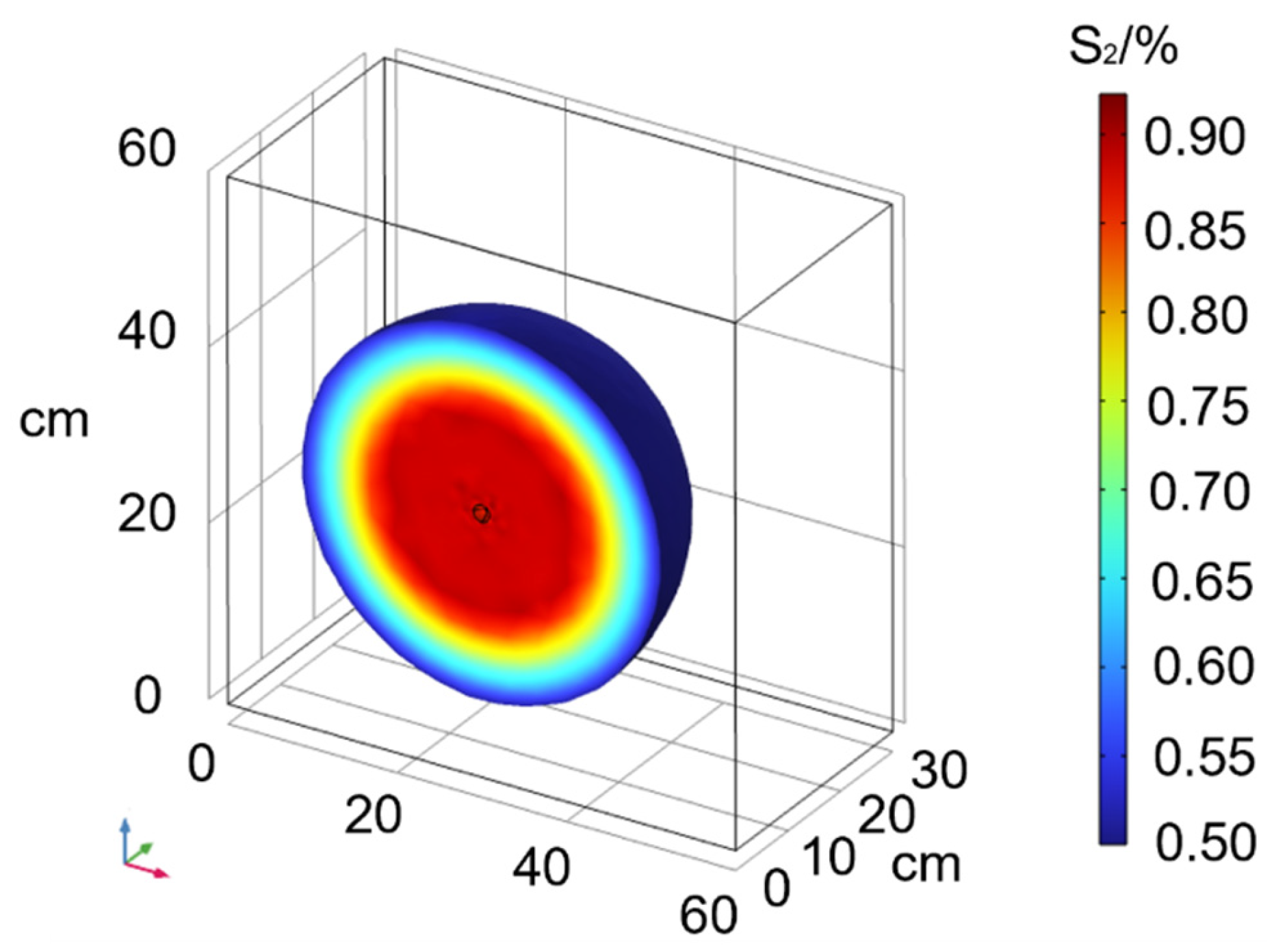
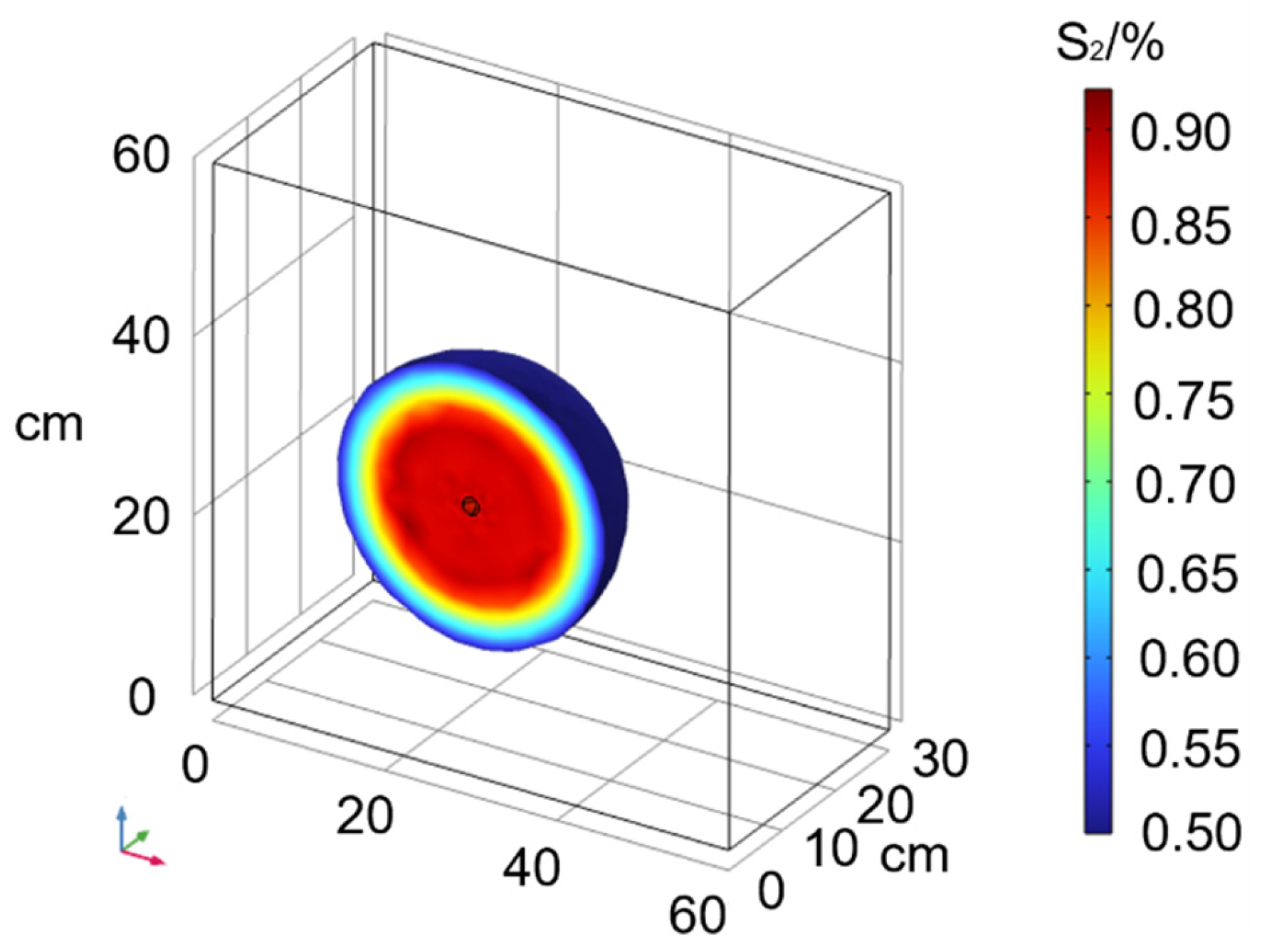
5.3. Analysis of Numerical Simulation Results

Figure 13 and Figure 14 represent the numerical simulation results for Experiment Condition 1 in the scenarios without considering and considering particle size distribution in the porous medium, respectively. Figure 15 shows a comparison between the two scenarios.
From Figure 12, Figure 13 and Figure 14, it is evident that the Newtonian fluid exhibits a spherical diffusion pattern both when considering and not considering porous media with different particle size distributions. When considering porous media with different particle size distributions, the diffusion radius of the Newtonian fluid is smaller than that in porous media without considering particle size distributions.

6. Comparison of Theoretical Analysis, Numerical Simulation, and Model Testing

In this section, based on the experimental results, a comparative analysis is conducted between the theoretical and numerical simulation results to validate the correctness of the theoretical and numerical models. The comparison results are presented in Figure 16 and Table 5.
From Figure 16 and Table 5, the following can be observed:
(1)
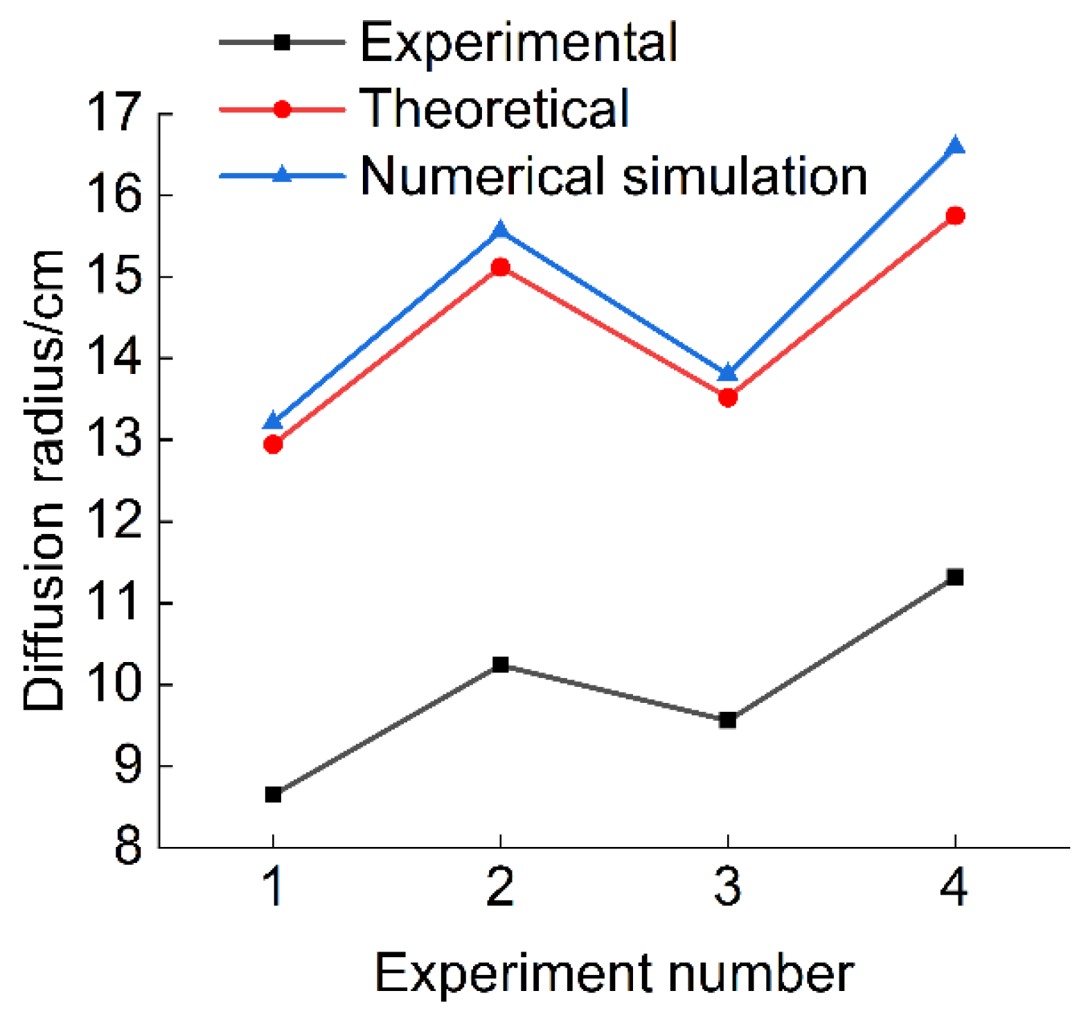
Regardless of whether considering the different particle size distributions, the theoretical results and numerical simulation results have only minor differences, with deviations of within 8%. This suggests that numerical simulations can effectively replicate the diffusion process of Bingham fluid slurry in porous media.
(2)
When considering the different particle size distributions in porous media, the theoretical diffusion radius closely matches the experimental results, compared to the theoretical diffusion radius without considering different particle size distributions in porous media.

7. Conclusions

This study, through theoretical analysis, laboratory experiments, and numerical simulations, has established the permeation grouting mechanism of Bingham fluid in porous media with different particle size distributions. This mechanism effectively explains the impact of particle size distribution variations in porous media on the diffusion of Bingham fluid. The main conclusions of this research are as follows:
(1)
Based on the theory of porous media fractal geometry and the rheological equation of Bingham fluid, a theoretical model for the infiltration grouting of Bingham fluid in porous media with different particle size distributions was established. This model reveals the infiltration grouting mechanism of Bingham fluid in porous media composed of different particle sizes.
(2)
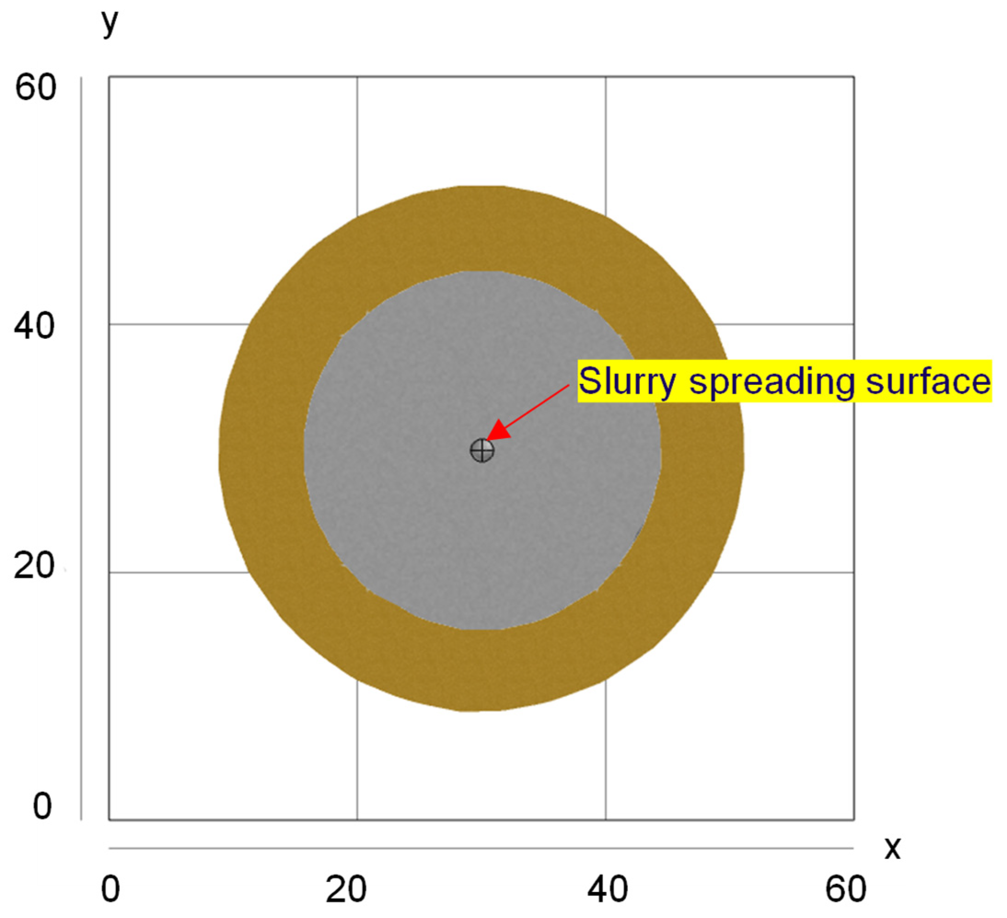
The diffusion form of Bingham fluid in porous media conforms to the theoretical model of spherical seepage grouting. In the process of grouting test, the parallel electrical instrument can be used to control the diffusion form of slurry macroscopically. In the experiment, the diffusion radius of Bingham fluid in sand and gravel is 31.8% smaller than the theoretical diffusion radius considering the particle size distribution of sand and gravel. At the same time, the diffusion radius of Bingham fluid considering particle size distribution in sand and gravel is smaller than that without considering particle size distribution.
(3)
The theoretical model and numerical simulation model obtained by considering the different particle size distribution can effectively describe the infiltration and diffusion mechanism of Bingham fluid in sand and gravel with different particle size distribution. The seepage grouting model deduced by considering the particle size distribution and the established numerical simulation model are more consistent with the experimental measurements.
In conclusion, the presented spherical permeation grouting mechanism for Bingham fluids, considering varying particle size distributions in gravelly soil, provides a more accurate depiction of the permeation and diffusion patterns of Bingham fluids in gravelly soil compared to the mechanism that neglects particle size distribution. The investigation into the influence of different particle size distributions in porous media on permeation grouting, as explored in this study, holds significance for both practical grouting engineering applications and theoretical research.

Author Contributions

The source of the subject, the acquisition of funds, the experimental design, and the first draft were carried out by B.X.; the experimental construction, data analysis and chart drawing were carried out by B.X., H.Z., J.Y. and Y.X. All authors contributed to the study. All authors have read and agreed to the published version of the manuscript.

Funding

This study was supported by the National Natural Science Foundation of China (52204081, 52174105).

Data Availability Statement

Data is contained within the article.

Conflicts of Interest

The authors declare no conflict of interest.

References

  1. Rahmani, H.; Naeini, S.A. Influence of non-plastic fine on static iquefaction and undrained monotonic behavior of sandy gravel. Eng. Geol. 2020, 275, 105729. [Google Scholar] [CrossRef]
  2. Guo, T.; Zhang, Z.; Yang, Z.; Zhu, Y.; Yang, Y.; Guo, Y.; Wang, R.; Zhang, B.; Fang, Y.; Yu, D.; et al. Penetration grouting mechanism of time-dependent power-law fluid for reinforcing loose gravel soil. Minerals 2021, 11, 1391. [Google Scholar] [CrossRef]
  3. Achour, Y.; Boumezbeur, A.; Hadji, R.; Chouabbi, A.; Cavaleiro, V.; Bendaoud, E.A. Landslide susceptibility mapping using analytic hierarchy process and information value methods along a highway road section in Constantine, Algeria. Arab. J. Geosci. 2017, 10, 194. [Google Scholar] [CrossRef]
  4. Nguyen, L.C.; Tien, P.V.; Do, T.N. Deep-seated rainfall-induced landslides on a new expressway: A case study in Vietnam. Landslides 2020, 17, 395–407. [Google Scholar] [CrossRef]
  5. Liu, J.; Ge, H.; Zhang, Z.; Wang, X.; Wang, J. Influence of mechanical contrast between the matrix and gravel on fracture propagation of glutenite. J. Pet. Sci. Eng. 2022, 208, 109639. [Google Scholar] [CrossRef]
  6. Li, T.; He, B.; Chen, Z.; Zhang, Y.; Liang, C. Effects of gravel on concentrated flow hydraulics and erosion in simulated landslide deposits. Catena 2017, 156, 197–204. [Google Scholar] [CrossRef]
  7. Xu, J.; Pu, H.; Sha, Z. Mechanical behavior and decay model of the sandstone in Urumqi under coupling of freeze–thaw and dynamic loading. Bull. Eng. Geol. Environ. 2021, 80, 2963–2978. [Google Scholar] [CrossRef]
  8. Rahmani, H.; Scanlan, C.; Nadeem, U.; Bennamoun, M.; Bowles, R. Automated segmentation of gravel particles from depth images of gravel-soil mixtures. Comput. Geosci. 2019, 128, 1–10. [Google Scholar] [CrossRef]
  9. Hubler, J.F.; Athanasopoulos-Zekkos, A.; Zekkos, D. Pore Pressure Generation of Gravelly Soils in Constant Volume Cyclic Simple Shear. J. Geotech. Geoenviron. Eng. 2023, 149, 04022130. [Google Scholar] [CrossRef]
  10. Rasouli, R.; Hayashi, K.; Zen, K. Controlled permeation grouting method for mitigation of liquefaction. J. Geotech. Geoenviron. Eng. 2016, 142, 04016052. [Google Scholar] [CrossRef]
  11. Park, D.S.; Oh, J. Permeation grouting for remediation of dam cores. Eng. Geol. 2018, 233, 63–75. [Google Scholar] [CrossRef]
  12. Xiuzhu, Y.; Jinshan, L.; Linong, X.; Xinghua, W. Power-law slurry diffusion radius. Geotechnics 2005, 26, 112–115. [Google Scholar]
  13. Xiuzhu, Y.; Xinghua, W.; Jinshan, L. Study and application of slurry diffusion radius in Bingham body. J. Water Resour. 2004, 6, 75–79. [Google Scholar]
  14. Yang, Z.Q.; Hou, K.P.; Guo, T.T.; Ma, Q. Study on column-hemispherical infiltration grouting mechanism of viscosity time-varying Bingham body slurry. Geotechnics 2011, 32, 2697–2703. [Google Scholar]
  15. Zhiquan, Y.; Xiangdong, N.; Kepeng, H.; Yanhui, G.; Wei, L.; Zonghong, Z. Power-law fluid column infiltration grouting mechanism. J. Harbin Inst. Technol. 2016, 48, 178–183. [Google Scholar]
  16. Axelsson, M.; Gustafson, G.; Fransson, Å. Stop mechanism for cementitious grouts at different water-to-cement ratios. Tunn. Undergr. Space Technol. 2009, 24, 390–397. [Google Scholar] [CrossRef]
  17. Lee, M.S.; Kim, J.S.; Lee, S.D.; Choi, Y.J.; Yang, J.M.; Lee, I.M. Effect of vibratory injection on grout permeation characteristics. J. Korean Geotech. Soc. 2010, 26, 37–47. [Google Scholar]
  18. Weng, L.; Wu, Z.; Zhang, S.; Liu, Q.; Chu, Z. Real-time characterization of the grouting diffusion process in fractured sandstone based on the low-field nuclear magnetic resonance technique. Int. J. Rock Mech. Min. Sci. 2022, 152, 105060. [Google Scholar]
  19. Wang, C.; Diao, Y.; Guo, C.; Li, P.; Du, X.; Pan, Y. Two-stage column–hemispherical penetration diffusion model considering porosity tortuosity and time-dependent viscosity behavior. Acta Geotech. 2023, 18, 2661–2680. [Google Scholar]
  20. Escobal-Marcos, I.; Álvarez-Fernández, M.-I.; Prendes-Gero, M.-B.; González-Nicieza, C. Designing Cement-Based Grouting in a Rock Mass for Underground Impermeabilization. Energies 2021, 14, 4062. [Google Scholar] [CrossRef]
  21. Zhu, Y.; Sun, H.; Xu, S.; Hu, L.; Cao, H.; Cai, Y.; Liu, J. Mechanics of the penetration and filtration of cement-based grout in porous media: New insights from CFD–DEM simulations. Tunn. Undergr. Space Technol. 2023, 133, 104928. [Google Scholar]
  22. Farhangi, V.; Karakouzian, M.; Geertsema, M. Effect of micropiles on clean sand liquefaction risk based on CPT and SPT. Appl. Sci. 2020, 10, 3111. [Google Scholar]
  23. Zhang, T.; Li, Y.; Li, Y.; Sun, S.; Gao, X. A self-adaptive deep learning algorithm for accelerating multi-component flash calculation. Comput. Methods Appl. Mech. Eng. 2020, 369, 113207. [Google Scholar] [CrossRef]
  24. Zhang, T.; Zhang, Y.; Katterbauer, K.; Al Shehri, A.; Sun, S.; Hoteit, I. Phase equilibrium in the hydrogen energy chain. Fuel 2022, 328, 125324. [Google Scholar]
  25. Yang, Z.; Zhang, D.; Li, C.; Zhang, Z.; Zhu, Y.; Yang, Y.; He, N.; Bai, X.; Xi, W.; He, D.; et al. Column Penetration and Diffusion Mechanism of Bingham Fluid Considering Displacement Effect. Appl. Sci. 2022, 12, 5362. [Google Scholar] [CrossRef]
  26. Zou, L.; Håkansson, U.; Cvetkovic, V. Yield-power-law fluid propagation in water-saturated fracture networks with application to rock grouting. Tunn. Undergr. Space Technol. 2020, 95, 103170. [Google Scholar]
  27. Lavrov, A. Flow of non-newtonian fluids in single fractures and fracture networks: Current status, challenges, and knowledge gaps. Eng. Geol. 2023, 321, 107166. [Google Scholar]
  28. Shamu, T.J.; Zou, L.; Kotzé, R.; Wiklund, J.; Håkansson, U. Radial flow velocity profiles of a yield stress fluid between smooth parallel disks. Rheol. Acta 2020, 59, 239–254. [Google Scholar]
  29. Yang, X.; Lei, J.S.; Xia, L.N. Study of power-law type slurry diffusion radius, China. Rock Soil Mech. 2008, 26, 1083–1086. [Google Scholar]
  30. Xu, P.; Yu, B. Developing a new form of permeability and Kozeny–Carman constant for homogeneous porous media by means of fractal geometry. Adv. Water Resour. 2008, 31, 74–81. [Google Scholar]
  31. Xu, P.; Yu, B.; Qiao, X.; Qiu, S.; Jiang, Z. Radial permeability of fractured porous media by Monte Carlo simulations. Int. J. Heat Mass Transf. 2013, 57, 369–374. [Google Scholar]
  32. Chen, X.; Yuan, C. Study of Bingham-type slurry column permeability law in porous media, China. J. Min. Saf. Eng. 2021, 38, 800–809. [Google Scholar]
  33. Lv, M. A Study of Some Flow Characteristics of Fluids in Porous Media. Ph.D. Thesis, Huazhong University of Science and Technology, Wuhan, China, 2008. [Google Scholar]
  34. Kong, X.Y. Advanced Seepage Mechanics; University of Science and Technology of China Press: Hefei, China, 1999. [Google Scholar]
  35. Li, Y.Z.; Yuan, M.S. Fluid Mechanics; Higher Education Press: Beijing, China, 1998. [Google Scholar]
  36. Yang, Z.; Chen, M.; Ding, Y.; Yang, Y.; Zhu, Y.; Guo, Y.; Wang, R.; Zhang, B.; Fang, Y.; Yu, D.; et al. Influence of Coupling Effects of Time and Water-to-Cement Ratio on Rheological Properties of Bingham Cement Grouts. Adv. Mater. Sci. Eng. 2021, 2021, 5781753. [Google Scholar] [CrossRef]
  37. Yang, Q. Theoretical and Simulation Experimental Study of Cement Slurry Grouting in Small-Size Gravel Body. Master’s Thesis, Kunming University of Science and Technology, Kunming, China, 2008. [Google Scholar]
Figure 1. Schematic representation of spherical permeation grouting.
Applsci 13 11986 g001
Figure 2. A0 schematic diagram.
Applsci 13 11986 g002
Figure 3. Indoor infiltration grouting system (a—nitrogen pressure reducer, b—nitrogen cylinder, c—test chamber, d—porous medium, e—grouting pipe, f—slurry storage tank, g—high-precision electronic scales, h—high-definition video camera, i—pressure sensor, j—electrical cable, k—base stations, l—parallel electrometer mainframe, m—PC processing host, n—pressure gauge, o—actual grout body).
Applsci 13 11986 g003
Figure 4. Particle gradation curves for sand and gravel with different porosity.
Applsci 13 11986 g004
Figure 5. Bingham Fluid Production Process.
Applsci 13 11986 g005
Figure 6. Schematic diagram of sensing electrode placement.
Applsci 13 11986 g006
Figure 7. Working 1 slurry body versus apparent resistivity diagram.
Applsci 13 11986 g007
Figure 8. Comparison analysis of experimental and theoretical models.
Applsci 13 11986 g008
Figure 9. Relationship between infiltration grouting pressure and slurry diffusion.
Applsci 13 11986 g009
Figure 10. Porosity versus slurry diffusion.
Applsci 13 11986 g010
Figure 11. Relationship between water-cement ratio and slurry diffusion.
Applsci 13 11986 g011
Figure 12. Schematic diagram of stochastic porosity versus permeability of S1 formation.
Applsci 13 11986 g012
Figure 13. Simulation without considering different particle size distributions.
Applsci 13 11986 g013
Figure 14. Simulation diagram considering different particle size distributions.
Applsci 13 11986 g014
Figure 15. Comparison of results with and without particle size distribution.
Applsci 13 11986 g015
Figure 16. A comparison of experimental, theoretical, and numerical simulation results.
Applsci 13 11986 g016
Table 1. Physical properties of gravels with different porosities.
Different Porosities/%Densities ρ / g · c m 3 Permeability Coefficient K / c m · s 1 Fractal Dimension
D f
Maximum Pore Radius r m a x
φ = 40.51.5700.882.6960.0367
φ = 44.71.4592.922.7380.0420
φ = 50.41.30110.162.7750.0480
Table 2. Rheological equations for cement slurries with water–cement ratios of 1.0 and 1.2.
W/CRheological Equation
1.0 τ = 0.8593 + 0.0169 γ
1.25 τ = 0.1136 + 0.0159 γ
Table 3. Indoor test protocol.
Working ConditionPorosityGrouting Pressure/MPaW/CGrouting Time/s
10.400.041.2515.5
20.450.061.0013.2
30.50.041.0011.6
40.45 0.061.2514.8
Table 4. Experimental values and theoretical calculations for the two different models.
Working ConditionTheoretical Value/cmExperimental Value/cm
Considering Different Particle Size DistributionsNot Considering Different Particle Size Distributions
112.9518.718.65
215.1227.3910.24
313.5224.859.56
415.7529.2511.32
Table 5. Comparison of theoretical analysis, numerical simulation, and experimental results.
Operating ConditionsTheoretical Calculation
Values/cm
Numerical Simulation Results/cmExperimental Results/cm
Values Obtained from Equation (16)Values Obtained from Equation (18)Values Obtained from Equation (16)Values Obtained from Equation (18)
112.9518.7113.2119.218.65
215.1227.3915.5628.9510.24
313.5224.8513.8025.749.56
415.5729.2516.5930.2111.32
Disclaimer/Publisher’s Note: The statements, opinions and data contained in all publications are solely those of the individual author(s) and contributor(s) and not of MDPI and/or the editor(s). MDPI and/or the editor(s) disclaim responsibility for any injury to people or property resulting from any ideas, methods, instructions or products referred to in the content.

