1. Introduction
Satcom-on-the-Move (SOTM) refers to the installation of satellite signal antennas on moving carriers, which can control the direction of the antenna to align with the communication satellite in real-time during the movement of the SOTM carrier, thus achieving a stable transmission link between the satellite and SOTM [
1,
2,
3,
4]. With the development of technology, satellite communication is becoming increasingly widespread [
5,
6,
7,
8]. Currently, the application of array antennas in SOTM systems is a very important development direction [
9,
10,
11]. Array antennas in SOTM systems are generally used on moving carriers with high height restrictions, including civilian vehicles, unmanned aerial vehicles (UAV), commercial aircraft, etc. [
12,
13,
14,
15]. Multi-beam array antennas have achieved significant research results in radar and conventional satellite communication fields [
16,
17], but their application in SOTM is still in the early stages, and there is currently limited research in this area.
The current systems that use array antennas generally employ a combination of electronic beam steering and mechanical tracking control methods [
18]. Ref. [
19] designed a stepper motor servo control system based on the analysis of the SOTM servo control system and proposed a speed-position dual-closed-loop PID controller with disturbance compensation. In Ref. [
20], a modeling method for a three-axis SOTM antenna based on a novel modified Denavit–Hartenberg method was investigated, which addresses the gimbal lock issue by adding a roll axis in addition to the conventional azimuth and elevation axes. Ref. [
21] designed an Active Disturbance Rejection Controller based on particle swarm optimization to overcome the issues of response speed and accuracy for the SOTM antenna servo control system. Ref. [
22] designed a Ku-band SOTM structure that included multiple distributed panels capable of mechanical oscillation and presented a new pseudo-monopulse tracking method. The SOTM systems utilize Global Navigation Satellite Systems (GNSS), compasses, and inertial navigation systems to measure the position and attitude of the carrier, automatically adjusting the azimuth angle and elevation angle of the antenna beam to align with the target communication satellite. The application of the SOTM systems is becoming increasingly widespread [
23,
24], and their operating conditions are becoming more complex, as they are unknown and dynamically changing [
25]. Due to the carrier’s motion, its location and attitude are constantly changing [
26], and current methods can meet the satellite tracking requirements of array carriers in general motion states. However, when the carrier’s attitude changes beyond certain conditions, from reference [
27], this condition is generally described as angular velocity
, or angular acceleration
, conventional methods may cause a decline in the communication effectiveness of the SOTM system and even cause the antenna to lose the tracking of the satellite and interrupt the communication. After the antenna loses the communication satellite, reacquisition relies on the antenna beam scanning and mechanical tracking system azimuth and elevation axis movements, which increases the time it takes to reacquire the satellite. Currently, research on the high maneuverability of carriers mainly focuses on the estimation of carrier attitude and location [
28,
29,
30,
31,
32,
33], and research on array antenna tracking satellites under a high maneuvering state is limited.
The contributions of this paper are as follows: Uninterrupted satellite communication is essential in various applications, such as military and emergency communication. To maintain the high communication quality of SOTM systems while the carrier is in a high maneuvering state of motion, we propose a fast multiple-beam reacquisition scheme for array antennas. After the antenna experiences a loss of the satellite, it first performs preliminary signal recognition, then divides the array antenna into multiple beams for measurement, obtaining multiple points in the directional diagram and the energy level of each beam’s main lobe. Combining the directional diagram, the optimal or sub-optimal beam direction can be quickly calculated to improve the speed of capturing satellites for array antennas. Our research improved communication quality, shortened the time required for the SOTM antenna to reacquire the satellite, and enhanced the reliability of the SOTM systems, offering a practical solution to maintain communication effectiveness in a high maneuvering state.
The remainder of this paper is organized as follows.
Section 2 introduces SOTM and its servo control system, as well as the directivity of array antenna beams.
Section 3 presents a design method for multi-beam fast satellite seeking and acquisition.
Section 4 verifies the effectiveness of the designed method through experiments.
Section 5 is the final section of this paper, which provides the summary and conclusion.
2. Overview of the SOTM System
2.1. Principle of Satellite Tracking for SOTM Antennas
Currently, the majority of SOTM systems utilize conventional parabolic antennas. However, these antennas have several drawbacks, including large physical dimensions, low wind resistance, mechanical inertia during scanning, and slow tracking speed. As a result, they suffer from compromised communication reliability and security.
Compared to the parabolic antenna, the array antenna is a new high-tech satellite antenna. The array antenna is generally not indivisible but consists of multiple antenna elements, each of which can form a similar and non-directional antenna pattern. Although the gain of each individual antenna element in the array antenna is low, the collective effect of numerous well-designed and properly arranged elements results in a relatively high gain for the array antenna. Therefore, the array antenna meets the requirements of satellite communication systems. The phase between the signals of each antenna element in the array antenna can be adjusted, enabling the beam direction of the overall array antenna to be adjusted without the need for a mechanical system. The array antenna has the advantages of low delay in directional adjustment, high system capacity, strong anti-interference ability, and being lightweight.
Figure 1 illustrates the communication link structure of the SOTM system. The satellite ground station remains in a stationary state relative to the Earth’s surface. It establishes wired communication links with the Internet Service Provider (ISP), command center, etc. Simultaneously, it establishes wireless communication links with communication satellites.
The SOTM antenna is installed on a moving carrier, its location remains relatively stationary with respect to the moving carrier, and the communication link is established through wireless means. Network devices, such as modems and routers, primarily handle tasks such as data forwarding. They typically establish communication links with the SOTM system through cables. Additionally, they establish links with user terminal devices such as closed-circuit television (CCTV), personal computers (PC), smartphones (SP), etc., through cables or wireless communication; this enables the establishment of a complete communication link between the user’s terminal devices and entities such as the ISP and command center.
The carrier’s movement requires the SOTM antenna to continuously align with the communication satellite, ensuring a stable communication link.
Figure 2 depicts the structure of the SOTM system’s servo control system. Because the carrier may be in a moving state, the location and attitude of the carrier may change.
The SOTM system attitude calculation processor calculates the real-time attitude of the carrier through the fusion of the gyroscope, accelerometer, GNSS, and electronic compass. The SOTM main controller calculates the direction of the antenna beam based on the longitude, latitude, and altitude of the communication satellite, as well as the location and attitude of the carrier. The main controller adjusts the array antenna beam’s azimuth and elevation in real-time to track the communication satellite.
2.2. Directionality of the Array Antenna Beam
The array antenna contains multiple elements, which are generally uniformly arranged.
Figure 3 shows a schematic diagram of an N-element linear array.
In
Figure 3, multiple linear array elements are uniformly arranged along the
y-axis. Assuming the elements’ quantity is
and the distance between two elements is
, as the array factor is rotationally symmetric with respect to the
y-axis, we only need to research the array factor in any plane passing through the
y-axis. For example, by studying the plane with
, which is referred to as the
plane, we can obtain the array factor of the
plane.
where
is the excitation current of each element.
3. Multi-Beam Fast Tracking and Satellite Capture Method
3.1. Overall Scheme of Multi-Beam
According to the multi-beam array antenna’s characteristics, the array antenna is divided into multiple sections. When the moving carrier is in a normal state, the entire array antenna runs as a whole and completes stable tracking of the communication satellite through methods such as conical scanning. When the carrier is in a high maneuvering moving state, the SOTM array antenna is divided into multiple beams in order to prevent the antenna beam from losing track of the communication satellite. Each beam should be pointed to multiple locations near the current position. Then, through demodulation analysis and combining the energy distribution characteristics of the main lobe of the array antenna, the accurate antenna pointing direction can be quickly determined.
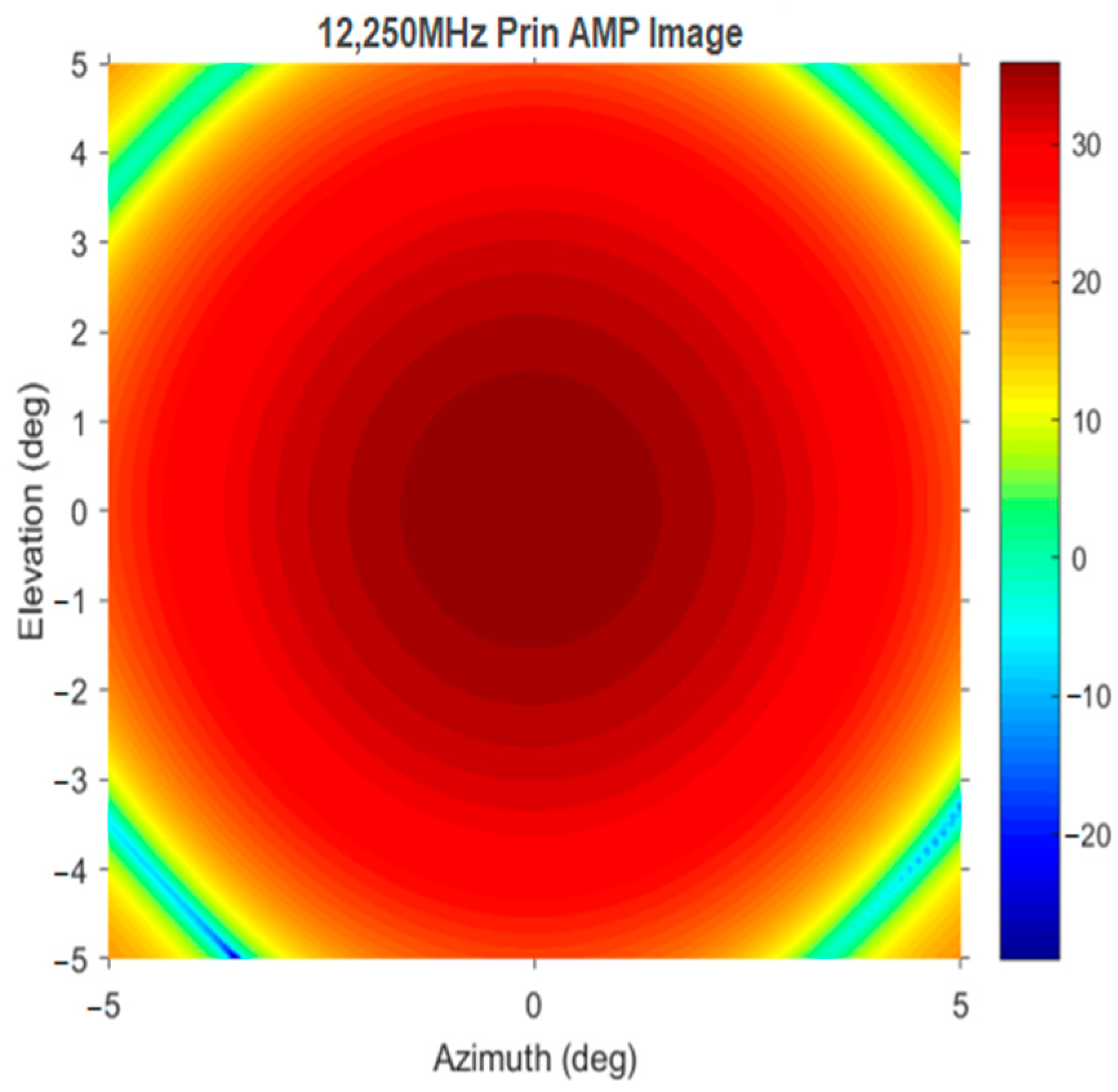
The previous section introduced the directivity of array antennas. This section uses the graphical representation of array antenna directivity, i.e., the directional pattern, to design a method for fast-tracking satellites by array antennas under a high maneuvering state.
Figure 4 and
Figure 5 show the wide-angle directional pattern and the main lobe beam directional pattern, respectively.
After dividing the entire array antenna into multiple beams by block, the main lobes of each beam become “fatter,” resulting in a larger beam coverage for the array antenna. When the SOTM carrier’s high maneuvering moving characteristics cause significant deviation in the tracking direction of the array antenna beam, if the array antenna works as a single beam due to its narrow beam, the satellite may deviate from the beam range of the array antenna due to the beam center being too far away from the communication satellite, leading to the loss of tracking the communication satellite by the array antenna. At this time, multiple “fatter” beams can scan simultaneously, resulting in an expansion of the beam scanning coverage range; this significantly increases the probability of the satellite being within the beam coverage range. Based on this, the rapid tracking scheme of this paper is designed.
The division of the array antenna into four beams is used as an example to illustrate the method of this paper. Assume that
Figure 6 represents the entire SOTM array antenna, where the black squares represent the elements. The number of black squares does not represent the specific number of elements in the array antenna; it is for illustration purposes only.
The array antenna is divided into four sub-blocks, each of which can form an independent beam, as shown in the schematic diagram in
Figure 7. It is necessary for the number of elements in each sub-block to be equal. In this way, each beam will point to a location close to the direction of the SOTM array antenna when it runs as a single beam; this corresponds to four points on the directional pattern, and the schematic diagram for multi-beam taking points on the directional pattern is shown in
Figure 8, in which, the black dots represent the pointing values of the 4 sub-beams, while the blue dot represents the theoretical target pointing value of the beam when the array antenna is running as a whole.
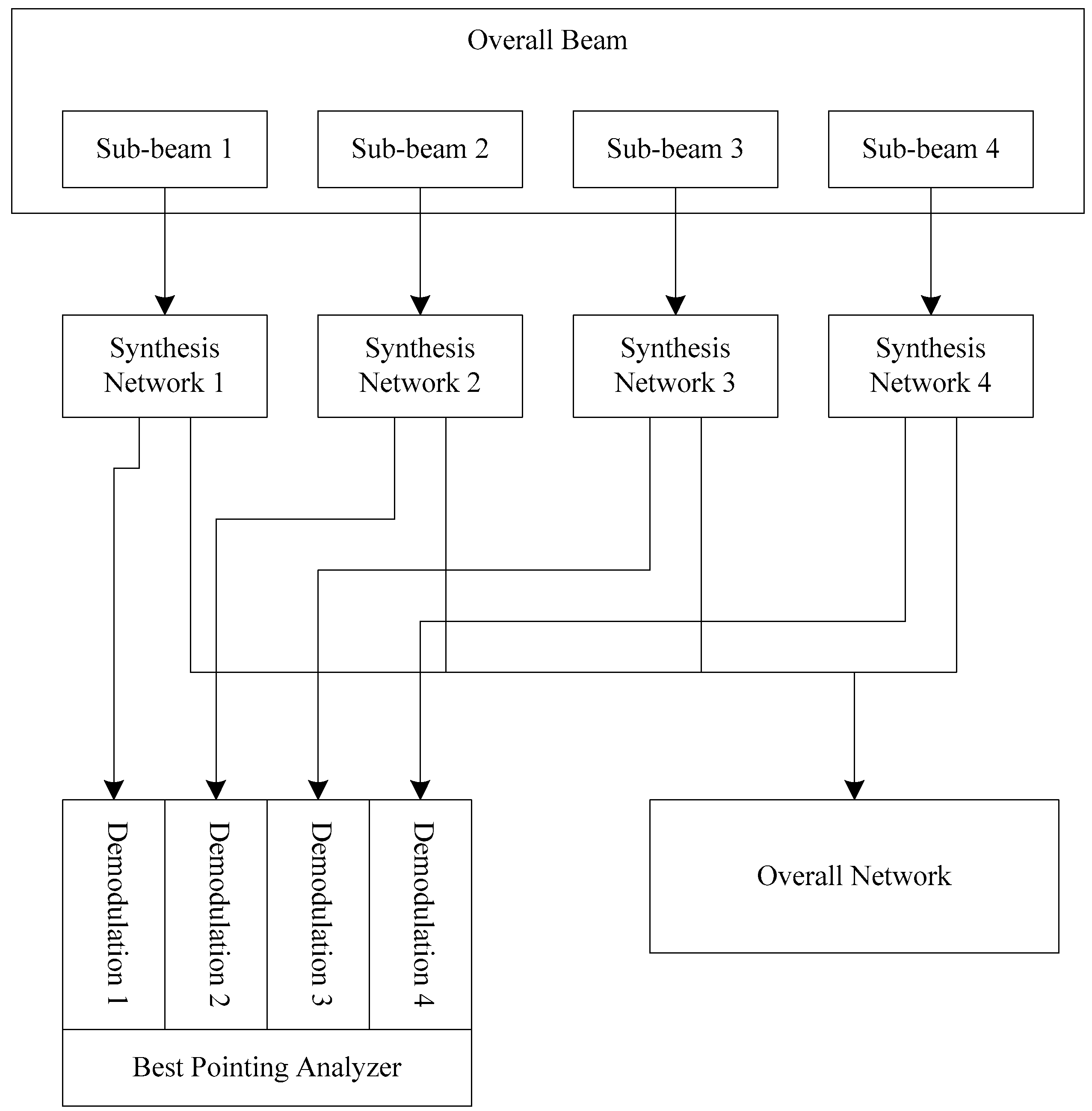
After achieving different pointing directions for each sub-beam in the multi-beam setup, carrier analysis is performed on each sub-beam and, combined with the energy distribution characteristics of the array antenna’s main lobe, the coordinate values of each sub-beam pointing direction in the directional pattern shown in
Figure 8 are calculated separately.
Figure 9 shows a schematic diagram of the design proposal. Each sub-beam is processed through its own synthesis network, and the processed data is sent to its own detection component. The detection component performs beam pointing and energy characteristic analysis on each sub-beam and sends the analyzed sub-beam pointing position coordinate values in the directional pattern to the optimal pointing analyzer. The optimal pointing analyzer analyzes and calculates an optimized array of antenna pointing information, which includes azimuth and elevation angles. This analysis is based on the coordinate values of the sub-beam pointing directions in the directional pattern.
3.2. A Multi-Beam Scheme for Antenna Non-Loss of Satellite
The workflow of the optimal pointing analyzer is analyzed below. The optimal pointing analyzer has different workflows for two different states of the SOTM system when the carrier is in a high maneuvering moving state. The first scenario is when the carrier is in a high maneuvering moving state, but the antenna beam is still capable of tracking the communication satellite, albeit with a reduced communication quality. The other scenario is when the SOTM antenna fails to maintain track of the satellite due to the high maneuvering state of the carrier, resulting in communication interruption.
For the first state of the SOTM system, as the communication has not been interrupted, the direction of the SOTM antenna beam is relatively close to the location of the satellite. Firstly, the array antenna is divided into four sub-beams, and the optimal pointing analyzer obtains the coordinate values of the four sub-beam pointing positions in the directional pattern for the four detection devices. As shown in
Figure 10, the four beam-pointing positions in the figure are A, B, C, and D, with coordinates
,
,
, and
, respectively. Here,
represents the azimuth coordinate of beam
in the directional pattern, which is the azimuth angle of beam
;
represents the elevation coordinate of beam
in the directional pattern, which is the elevation angle of beam
. Point E is located at the center of beams A, B, C, and D in the directional diagram. As the pointing direction of the SOTM antenna is relatively close to the location of the satellite in the current SOTM state and the sub-beams are widened, the point corresponding to the satellite in the directional pattern will be within the range formed by connecting points A, B, C, and D. Additionally, point E will be relatively close to the point corresponding to the satellite in the directional pattern. Therefore, point E is used as the target pointing direction of the array antenna. The coordinates of point E can be easily obtained. When the error in obtaining the coordinates of points A, B, C, and D is not considered, the coordinates of point E are:
However, for the actual system running in the directional pattern, there will always be errors in the coordinate values of points A, B, C, and D. To improve the accuracy of the location coordinate values of point E, the coordinate values of point E are obtained as follows:
After obtaining point E’s coordinate values in the directional pattern, the array antenna runs as a whole and uses single-beam alignment to obtain the increment of the azimuth and elevation angle values of point E relative to point C (or D) and point A (or B), respectively.
Considering the time-consuming nature of the array antenna’s electronic beam control, which operates at the millisecond level, the slight decrease in communication rate caused by the multi-beam searching process for antenna pointing can be disregarded due to its short duration. Therefore, in this multi-beam searching scheme for antenna pointing, the array antenna obtains multiple sub-beams through division and communicates as a whole, which can be regarded as parallel in macroscopic time and will not affect the normal operation of communication.
3.3. The Multi-Beam Scheme for Antenna Loss of Satellite
For the second stage of the SOTM system, when the SOTM antenna loses satellite connection, it is likely that the midpoint of the directional pattern is not within the range formed by connecting points A, B, C, and D in
Figure 10. In this case, calculations need to be performed. Here, we take the azimuth angle as an example to illustrate. First, the azimuth directional pattern of the main lobe is given, as shown in
Figure 11.
First, take the two points in the directional pattern of the four beams with the largest difference in azimuth angle. Assume that these two points are points C and D, with coordinates and , respectively. The signal energy values of these two points are and , respectively. Based on the numerical relationship between and and the signal energy values of the two points, the coordinates of points C and D in the azimuth pattern of the main lobe can be determined. When < and > , points C and D are located to the left of azimuth 0°; otherwise, they are located to the right of azimuth 0°.
Figure 12 is a schematic diagram for calculating the azimuth of the main lobe. The energy values of points C and D, denoted as
and
, respectively, have been obtained. Since the angle is a relative value based on the energy values of C and D, as well as the formula of the azimuth directional curve of the main lobe, the coordinates
and
of points C and D in the azimuth directional curve of the main lobe can be obtained, which represents the difference between points C and D and the highest point (i.e., the satellite direction) of the curve. The array antenna adjusts its azimuth angle deviation from point C by an angle
or from point D by an angle
, depending on which point is used as the reference. The same method can be used to obtain the required elevation angle adjustment for the antenna.
Although the equation of the curve is known, it contains many nonlinear components, including logarithmic functions, exponential functions, trigonometric functions, and inverse trigonometric functions. From a mathematical point of view, this processing process is relatively simple and does not require much discussion. However, from the perspective of engineering practice, the processing of these functions poses a great challenge to microprocessors. The processing process will consume much time and require high computational and storage performance of microprocessors. Therefore, a piecewise linearization method is adopted here to segmentally linearize the above functions, which greatly reduces the difficulty of microprocessor processing.
Figure 13 shows a schematic diagram of the piecewise linearization method for the azimuth directional curve of the main lobe. The black dots in the figure represent several points taken along the curve. These points are then connected by straight lines to form the red line segments denoted as
a,
b, …,
i in
Figure 13. The equation of each straight line is calculated as follows:
By storing the parameters of each straight line and the coordinate values at the endpoints on the local storage of the microprocessor, real-time data processing can be performed for this solution. It should be noted that the closer to the center point O, the more accurate the pointing needs to be, and the higher the requirement for the accuracy of the data. Hence, as we approach point O, the line segments become shorter, and the endpoints become more densely distributed.
4. Experiment
To verify the actual performance of the multi-beam method designed in this paper, experiments are conducted in this section for validation.
Figure 14 shows the array antenna used in this experiment. The antenna used in this experiment is a Ku-band multi-beam array antenna developed by SATPRO M&C Tech Co., Ltd. (Xi’an, China). The working frequency range of the antenna is 13.7–14.5 GHz. The typical value for the pointing switching time is 0.3 ms. The azimuth scanning range is 0–360°, and the elevation scanning range is 15–90°. It uses the SPI-RS422 control protocol.
Figure 15 shows the experimental site. Location: SATPRO M&C Tech Co., Ltd., Weiyang District, Xi’an, China. Time: 4 August 2022. Weather: Cloudy, 35 °C. Communication Satellite: YATAI 6D Geosynchronous Satellite. The yaw range of the swing platform was −15°~15°. The pitch range of the swing platform was −15°~15°. The toll range of the swing platform was −15°~15°.
The angles of the yaw, pitch, and roll of the swing platform run in a sinusoidal manner with a period of 3 s; the maximum angular velocity is 31.4159°/s, and the maximum angular acceleration is 65.7974°/s
2. From reference [
27], when the maximum angular velocity is greater than 30°/s or the maximum angular acceleration is greater than 40°/s
2, the swing platform may be in a high maneuvering state during the experiment.
To fully validate the design scheme of this paper, the experiment is divided into the following two experiments:
In this experiment, the carrier was in a high maneuvering moving state, the SOTM antenna did not lose track of the satellite, and the SOTM communication system ran normally. The conventional single-beam tracking method (referred to as the conventional method in this paper) and the multi-beam method proposed in this paper are compared and tested.
Figure 16 illustrates the real-time Automatic Gain Control (AGC) level of the SOTM system when using the multi-beam fast-tracking scheme with the SOTM array antenna designed in this paper, while
Figure 17 illustrates the real-time AGC level of the SOTM system when using the conventional scheme. From the perspective of the real-time AGC level of the SOTM antenna, it can be concluded that when the SOTM antenna remains connected to the satellite, even during the high maneuvering motion of the carrier, there is minimal disparity in communication quality between the two approaches. This result indicates that the multi-beam fast-tracking scheme proposed in this paper does not result in worse communication effects than the conventional scheme.
Figure 18 illustrates the real-time signal quality of the SOTM system when using the multi-beam fast-tracking scheme with the SOTM array antenna designed in this paper, while
Figure 19 illustrates the real-time signal quality of the SOTM system when using the conventional scheme. From the perspective of the real-time signal quality of the SOTM system, it can be concluded that when the SOTM antenna remains connected to the satellite, despite the high maneuvering motion of the carrier, the approach introduced in this paper can attain superior communication quality compared to the conventional scheme; this indicates that the multi-beam fast-tracking scheme proposed in this paper outperforms the conventional scheme.
Figure 20 illustrates the real-time Signal-to-Noise Ratio (SNR) value of the SOTM system when using the multi-beam fast-tracking scheme with the SOTM array antenna designed in this paper, while
Figure 21 illustrates the real-time SNR value of the SOTM system when using the conventional scheme. From the perspective of the real-time SNR of the SOTM system, it can be concluded that when the SOTM antenna remains connected to the satellite despite the high maneuvering state of the carrier, the proposed scheme in this paper can achieve better communication quality than the conventional scheme, with relatively high SNR and small fluctuations; this indicates that the multi-beam fast-tracking scheme proposed in this paper outperforms the conventional scheme.
From the results of Experiment 1, it could be concluded that when the carrier is in a high maneuvering moving state, and the SOTM system does not experience communication interruption, the multi-beam tracking scheme designed in this paper is superior to the conventional method. As for the real-time AGC level value, the results of the two schemes are close because the AGC level data retains two decimal places, and the real-time AGC level changes less when the SOTM system communication is normal.
In this experiment, physical obstruction was given to the SOTM antenna during its operation, causing the SOTM antenna to experience satellite loss. It should be noted that this physical obstruction was artificially given, and the time of the obstruction could not be accurately determined.
Figure 22 illustrates the real-time AGC level value of the SOTM system when using the multi-beam fast-tracking scheme proposed in this paper, while
Figure 23 illustrates the real-time AGC level value of the SOTM system when adopting the conventional scheme. It could be seen that the proposed method in this paper can reacquire the communication satellite in a significantly shorter time than the conventional method after the SOTM antenna experiences satellite loss; this indicates that the satellite acquisition capability of the method proposed in this paper is significantly better than that of the conventional method.
Figure 24 and
Figure 25 show the signal quality when using the multi-beam fast tracking scheme designed in this paper and the traditional scheme, respectively, while
Figure 26 and
Figure 27 show the SNR when using the multi-beam fast tracking scheme designed in this paper and the traditional scheme, respectively. Similarly, it can be concluded that the satellite acquisition capability of the method proposed in this paper is significantly better than that of the conventional method.
From the experimental results above, it can be seen that when the SOTM antenna remains connected to the satellite despite the high maneuvering state of the carrier, the proposed scheme in this paper can achieve better communication quality than the conventional scheme. When the SOTM experiences satellite loss and communication interruption, the proposed scheme in this paper can reacquire the satellite faster than the conventional scheme.


