


An Automated Parametric Surface Patch-Based Construction Method for Smooth Lattice Structures with Irregular Topologies


Abstract
:1. Introduction
2. Surface Construction Methods
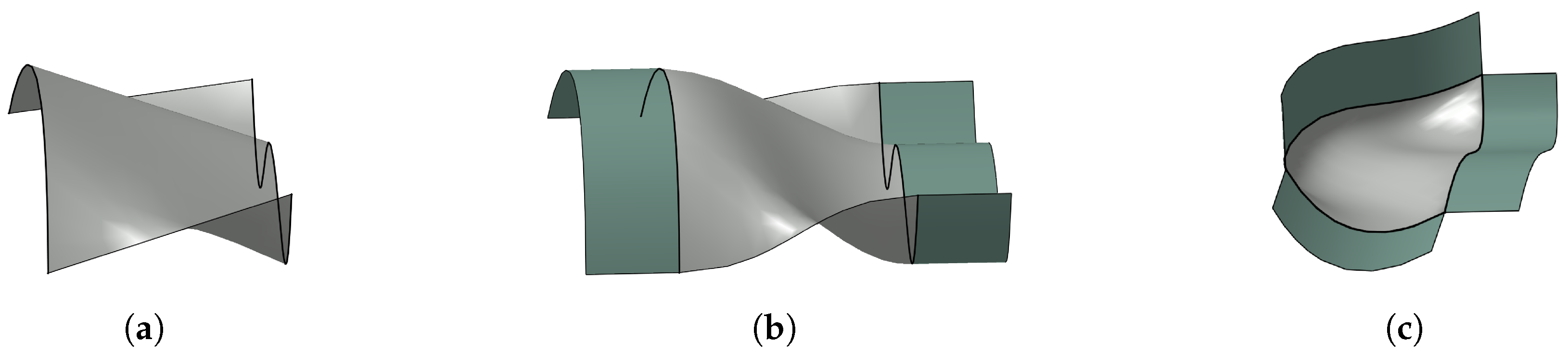
- If the ruled surface matches additional cross-boundary tangent conditions along b and c, it is denoted as -continuous ruled surface. An example is illustrated in Figure 1b. A method to impose geometric continuity on ruled surfaces can be found in [21]. This type of surface patch is used for the construction of struts and for smooth transitions between strut ends that converge to the same node.
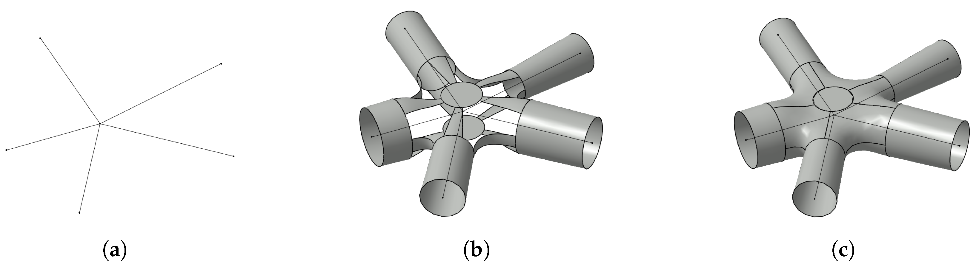
- Given a set of N boundary curves forming a loop, a surface patch filling the region inside the loop and meeting cross-boundary tangent conditions is denoted as -continuous N-patch. In Figure 1c, a -continuous 3-patch is sketched. Algorithms to construct this type of surface patch can be found in [22,23,24]. They are used in the lattice construction algorithm to fill regions between strut ends and their smooth transitions.
3. Lattice Construction Algorithm
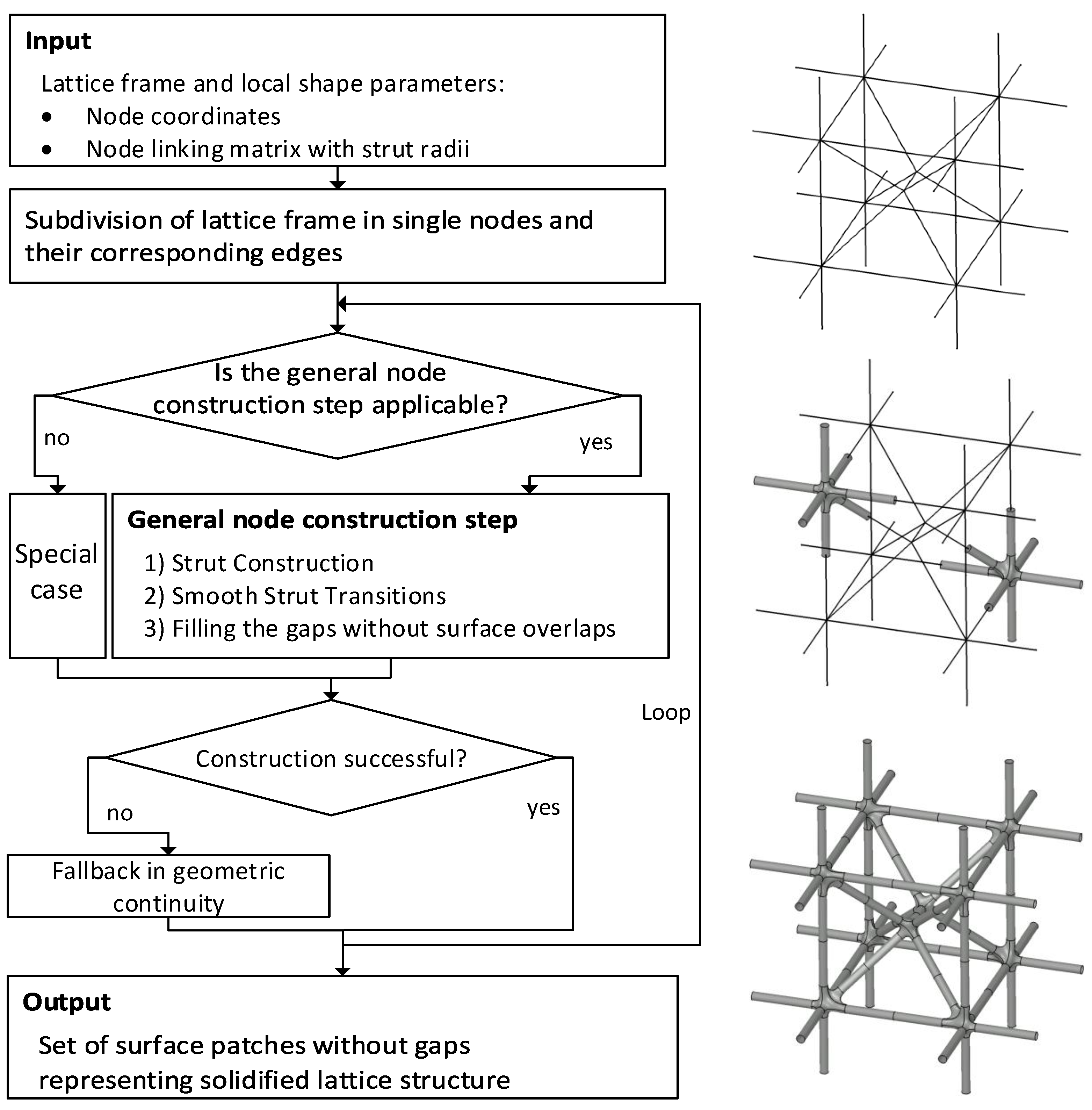
3.1. Input and Output
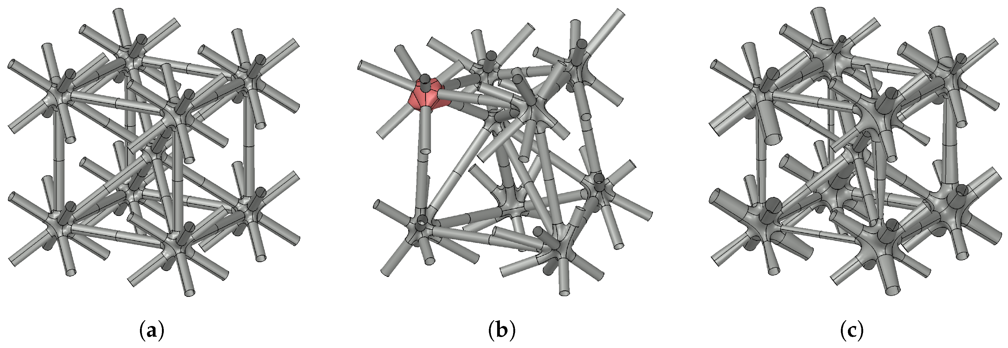
3.2. Subdivision of the Lattice Structure
3.3. General Node Construction Step
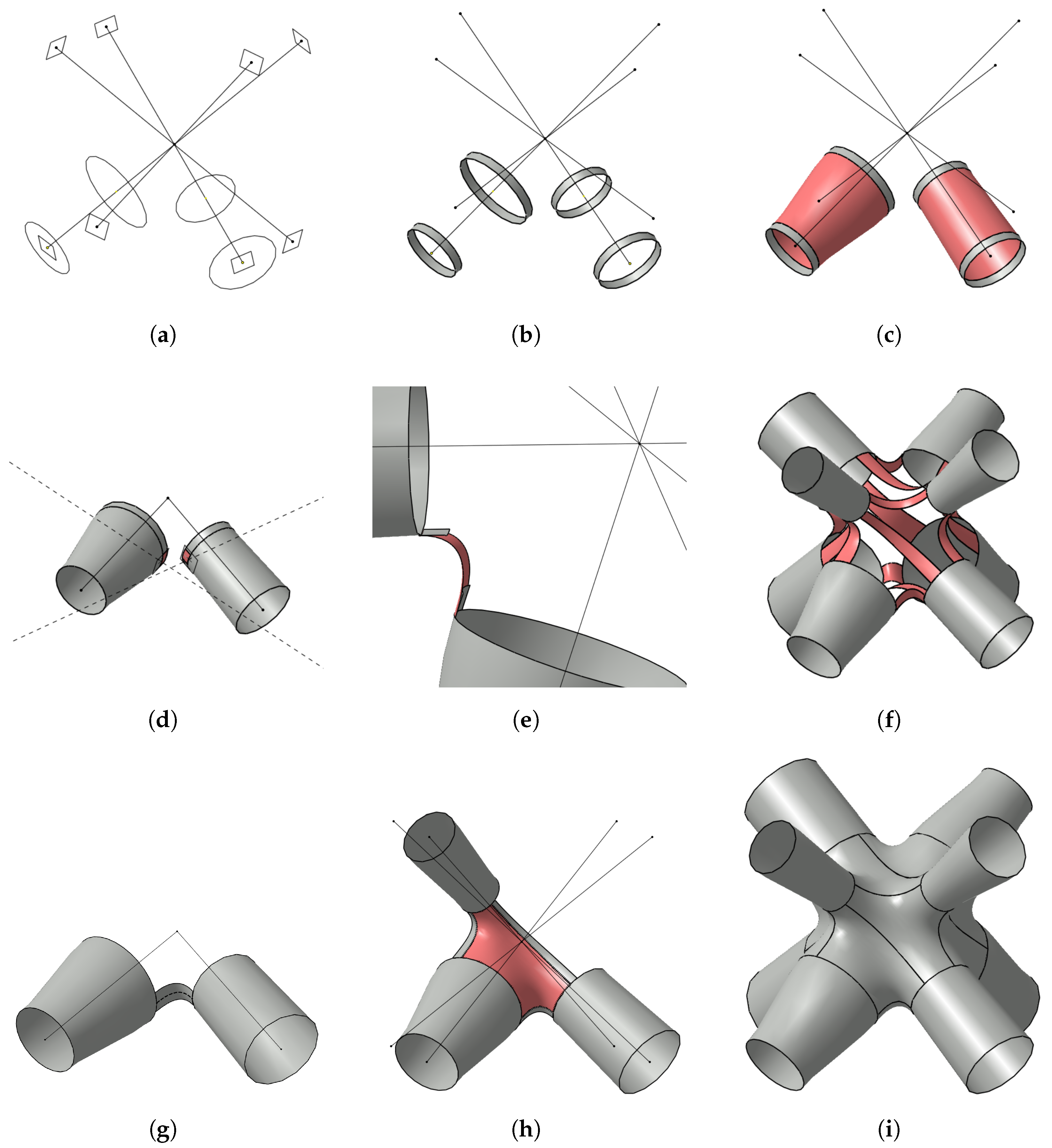
- 1.
- Strut construction
- (a)
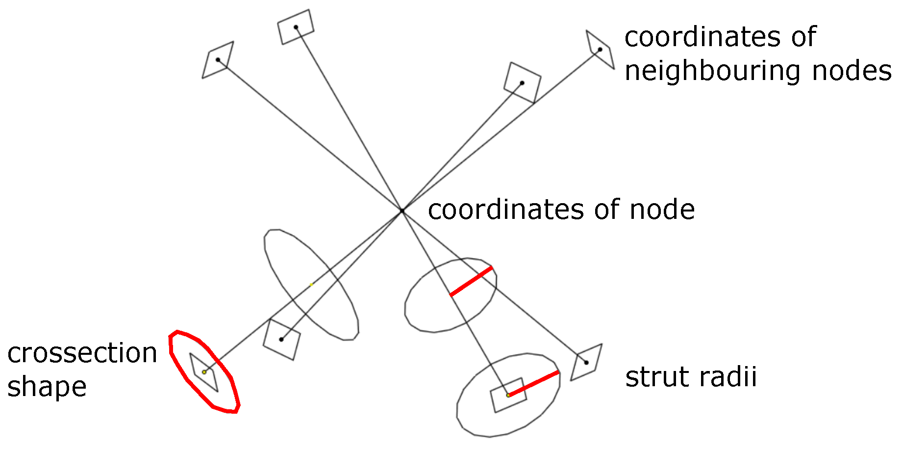
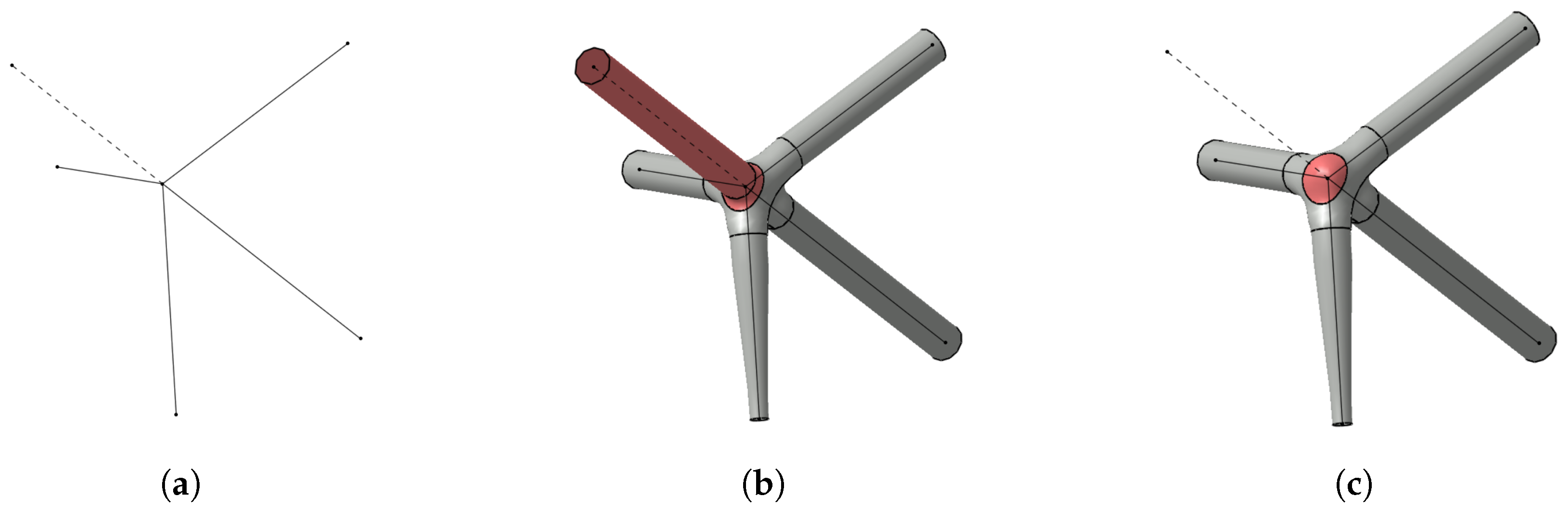
- For each neighbouring node, a point is constructed in the centre of the corresponding edge. In this point and perpendicular to the edge, a plane is defined in that a circle is constructed. The radius of the latter is chosen such that the given radii at the endpoints of the corresponding edge are interpolated linearly. Also perpendicular to the edge, a second plane and a circle within it are constructed (Figure 5a). The intersection point of the second plane with the edge is chosen far enough from the node such that the created circles corresponding to different edges are not intersecting each other. The radii of these circles are given by the input radii of the respective edges. By modifying the radii of the circles or by substituting the circles with other cross-section shapes in this step, the lattice structure is parametrised locally and exactly.
- (b)
- The circles constructed in the previous stage are copied and shifted about a small distance along their respective edges. Each circle and its copy are used as a pair of boundary curves for the definition of ruled surfaces (Figure 5b).
- (c)
- Along the circles, the ruled surfaces constructed in the previous stage are defining tangent planes. Thus, there is a -continuous ruled surface connecting the two original circles for each edge (Figure 5c). By that, the construction of the struts of the final lattice structure is already completed.
- 2.
- Smooth strut transitions
- (a)
- Now, suitable segments of the inner ruled surfaces are cut in order to define boundary conditions for smooth strut transitions. For each pair of struts that shall be connected, the plane spanned by the corresponding edges is intersected with the respective inner planes defined in strut construction step 1a. As a result, the dashed intersection lines (Figure 5d) are obtained. On each of these lines and within the circle, a point is chosen close to the latter. In this point, a plane perpendicular to the intersection line is defined. The inner ruled surface is cut through this plane, leading to the desired small segments (Figure 5d).
- (b)
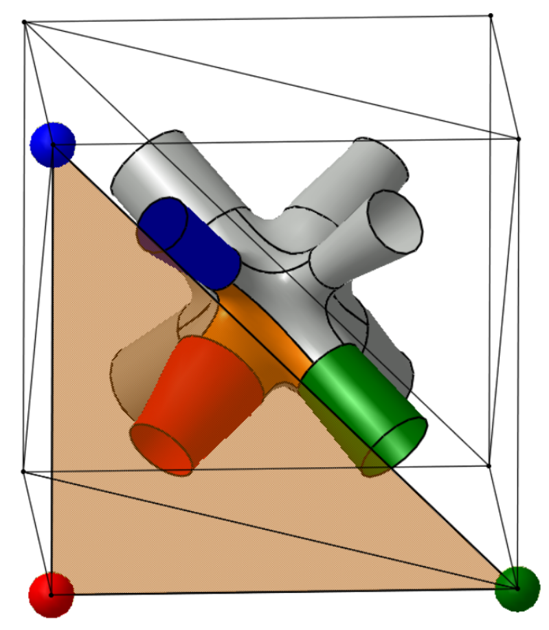
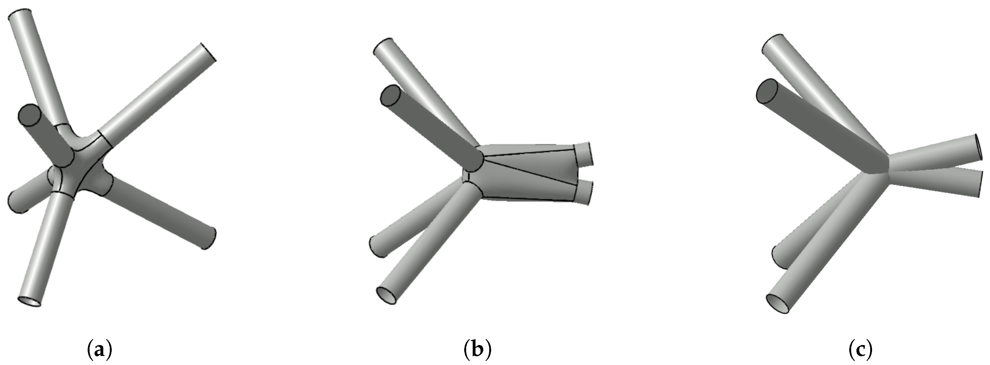
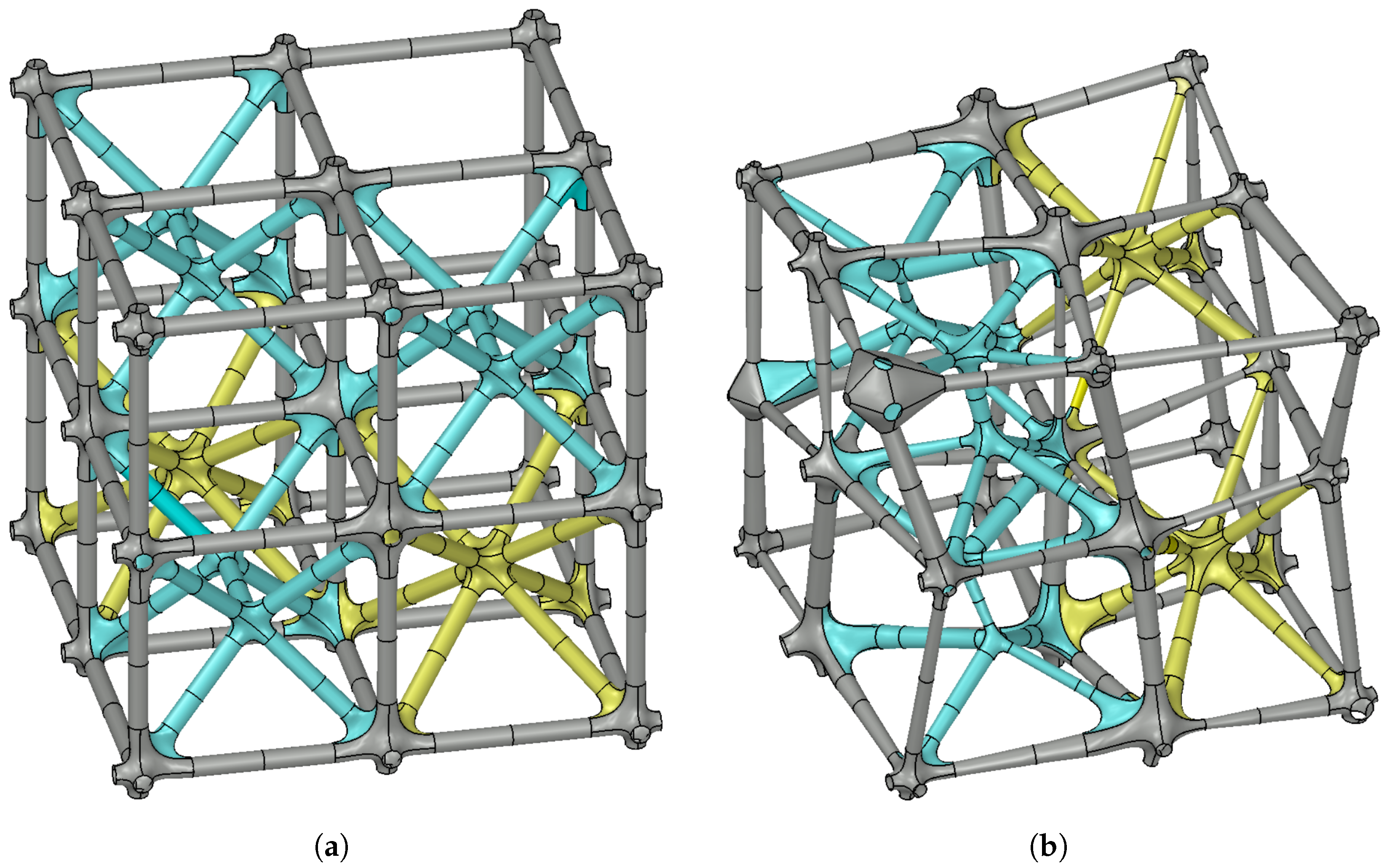
- In this construction stage, -continuous ruled surfaces are defined that smoothly connect some of the strut segments (Figure 5e). The decision of which segments (Figure 5f) should be connected is taken according to the geometry of the iteratively computed convex hull representation that is determined as follows: Initially, the convex hull of the points corresponding to the neighbouring nodes is computed. If one of these points is in the interior, i.e., the point is not a vertex of the convex hull, it is projected along its corresponding edge on the convex hull’s boundary. Then, the convex hull is iteratively recomputed and not simplified until each neighbouring node is represented by one vertex of the convex hull. This representation serves as an abstract model of the desired smooth node and is denoted as convex hull representation. Edges of the convex hull are translated into transitions using -continuous ruled surfaces and the triangular faces of the convex hull are translated into -continuous 6-patches filling the regions without gaps that are bounded by struts and their transitions (Figure 6).
- 3.
- Filling the gaps without surface overlaps
- (a)
- In the last construction stage, -continuous 6-patches are created for each face of the convex hull representation. Therefore, boundary curves are selected on the ruled surfaces that were constructed in the previous step. Each of the latter is intersected with the plane spanned by the two edges corresponding to the struts. The result of this intersection is the dashed curve (Figure 5g). Concatenating these curves with segments of the inner circles, constructed in the first strut construction step, the boundary of a 6-patch is defined. The tangent plane along this boundary curve is well-defined by the surface patches that were already constructed. The resulting 6-patch smoothly fills the region between three neighbouring struts (Figure 5h).
- (b)
- After having created one -continuous 6-patch per face of the convex hull representation and one -continuous ruled surface per neighbouring node, the ruled surfaces constructed in construction step 1b as well as 2b become obsolete for the representation of the lattice structures’ surface, because they are overlapping with other patches. Therefore, they can be neglected in the final set of surface patches that serves as an output for each node of the lattice frame (Figure 5i).
3.4. Special-Case Workarounds and Continuity Fallback Mechanism
- The neighbouring nodes of each node should not be coplanar or almost coplanar, i.e., more than three neighbouring nodes are required.
- The edges converging to a node should be distributed equally in space around the node such that in every half-space exists at least one edge.
- Sharp angles between edges should be avoided.
3.4.1. Workaround for Coplanar and Almost Coplanar Nodes
3.4.2. Workaround for Nodes with Edge-Free Half-Spaces
3.4.3. Geometric Continuity Fallback for Sharp Angles and Intricate Input
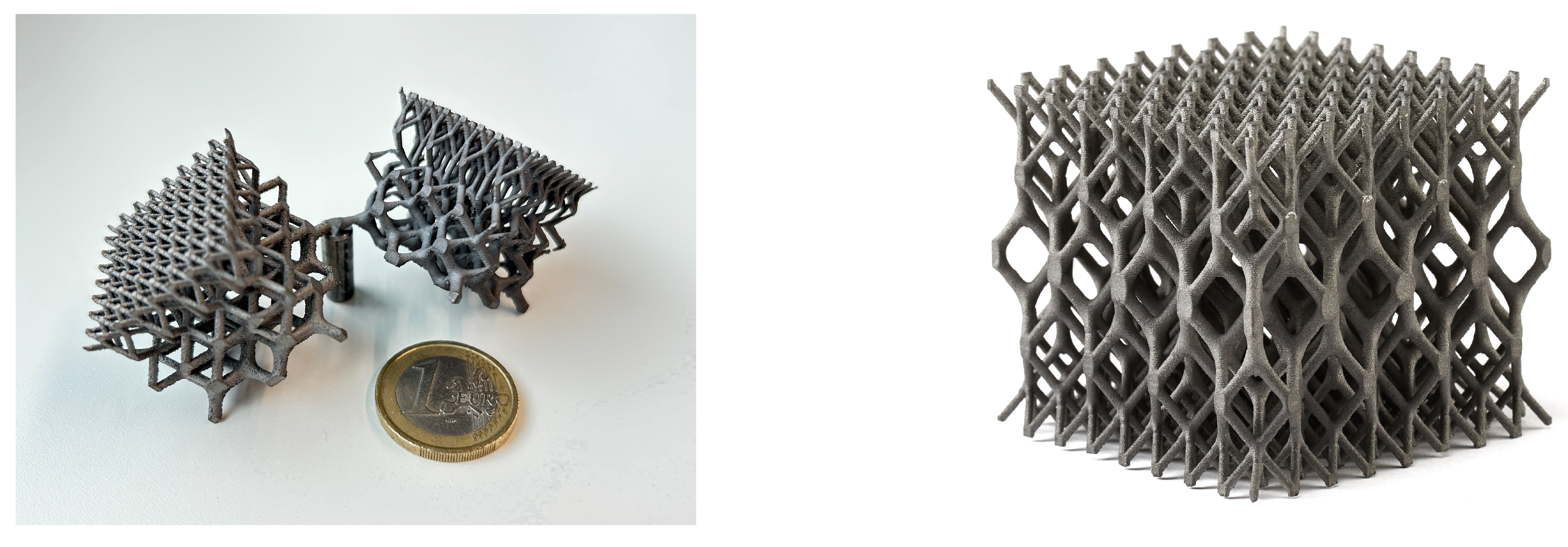
4. Demonstration, Application, and Discussion
5. Conclusions
Author Contributions
Funding
Institutional Review Board Statement
Informed Consent Statement
Conflicts of Interest
References
- Tang, Y.; Dong, G.; Zhao, Y.F. A hybrid geometric modeling method for lattice structures fabricated by additive manufacturing. Int. J. Adv. Manuf. Technol. 2019, 102, 4011–4030. [Google Scholar] [CrossRef]
- Nazir, A.; Abate, K.M.; Kumar, A.; Jeng, J.Y. A state-of-the-art review on types, design, optimization, and additive manufacturing of cellular structures. Int. J. Adv. Manuf. Technol. 2019, 104, 3489–3510. [Google Scholar] [CrossRef]
- Feng, J.; Fu, J.; Lin, Z.; Shang, C.; Li, B. A review of the design methods of complex topology structures for 3D printing. Vis. Comput. Ind. Biomed. Art 2018, 1, 5. [Google Scholar] [CrossRef] [PubMed]
- Mahmoud, D.; Elbestawi, M.A. Lattice Structures and Functionally Graded Materials Applications in Additive Manufacturing of Orthopedic Implants: A Review. J. Manuf. Mater. Process. 2017, 1, 13. [Google Scholar] [CrossRef]
- Vaissier, B.; Pernot, J.P.; Chougrani, L.; Véron, P. Parametric design of graded truss lattice structures for enhanced thermal dissipation. Comput. Aided Des. 2019, 115, 1–12. [Google Scholar] [CrossRef]
- Shinde, M.; Ramirez-Chavez, I.E.; Anderson, D.; Fait, J.; Jarrett, M.; Bhate, D. Towards an Ideal Energy Absorber: Relating Failure Mechanisms and Energy Absorption Metrics in Additively Manufactured AlSi10Mg Cellular Structures under Quasistatic Compression. J. Manuf. Mater. Process. 2022, 6, 140. [Google Scholar] [CrossRef]
- Boschetto, A.; Bottini, L.; Macera, L.; Vatanparast, S. Additive Manufacturing for Lightweighting Satellite Platform. Appl. Sci. 2023, 13, 2809. [Google Scholar] [CrossRef]
- Hoschke, K.; Pfaff, A.; Fleig, L.; Bierdel, M.; Jäcklein, M.; Riedel, W.; Hiermaier, S. A Parametric Mesostructure Approach for Robust Design of Additive Manufacturing Parts. In Proceedings of the Fraunhofer Direct Digital Manufacturing Conference (DDMC), Berlin, Germany, 14–15 March 2018. [Google Scholar]
- Ramsaier, M.; Till, M.; Schumacher, A.; Rudolph, S. On a Physics-based Reconstruction Algorithm for Generating Clean Parametric Native CAD-Models from Density-based Topology Optimization Results. In Proceedings of the World Congress of Structural and Multidisciplinary Optimization, Beijing, China, 20–24 May 2019. [Google Scholar]
- Maskery, I.; Aremu, A.; Parry, L.; Wildman, R.; Tuck, C.; Ashcroft, I. Effective design and simulation of surface-based lattice structures featuring volume fraction and cell type grading. Mater. Des. 2018, 155, 220–232. [Google Scholar] [CrossRef]
- Savio, G.; Meneghello, R.; Concheri, G. Geometric modeling of lattice structures for additive manufacturing. Rapid Prototyp. J. 2018, 24, 351–360. [Google Scholar] [CrossRef]
- Goel, A.; Anand, S. Design of Functionally Graded Lattice Structures using B-splines for Additive Manufacturing. Procedia Manuf. 2019, 34, 655–665. [Google Scholar] [CrossRef]
- Mattingly, W.A.; Chariker, J.H.; Paris, R.; Chang, D.J.; Pani, J.R. 3D modeling of branching structures for anatomical instruction. J. Vis. Lang. Comput. 2015, 29, 54–62. [Google Scholar] [CrossRef] [PubMed]
- Srinivasan, V.; Mandal, E.; Akleman, E. Solidifying Wireframes. In Proceedings of the 2004 Bridges Conference on Mathematical Connections in Art, Music, and Science. 2005. Available online: http://archive.bridgesmathart.org/2005/bridges2005-203.html (accessed on 7 September 2023).
- Al-Ketan, O.; Lee, D.W.; Rowshan, R.; Abu Al-Rub, R.K. Functionally graded and multi-morphology sheet TPMS lattices: Design, manufacturing, and mechanical properties. J. Mech. Behav. Biomed. Mater. 2020, 102, 103520. [Google Scholar] [CrossRef] [PubMed]
- Hu, C.; Lin, H. Heterogeneous porous scaffold generation using trivariate B-spline solids and triply periodic minimal surfaces. Graph. Model. 2021, 115, 101105. [Google Scholar] [CrossRef]
- Hassani, V.; Khabazi, Z.; Raspall, F.; Banon, C.; Rosen, D. Form-Finding and Structural Shape Optimization of the Metal 3DPrinted Multi-Branch Node with Complex Geometry. Comput. Aided Des. Appl. 2019, 17, 205–225. [Google Scholar] [CrossRef]
- Campbell, R.J.; Flynn, P.J. A survey of free-form object representation and recognition techniques. Comput. Vis. Image Underst. 2001, 81, 166–210. [Google Scholar]
- Gallier, J. Geometric Methods and Applications: For Computer Science and Engineering; Springer Science & Business Media: New York, NY, USA, 2001; Volume 38. [Google Scholar]
- Farin, G. Curves and Surfaces for CAGD: A Practical Guide; Morgan Kaufmann: Burlington, MA, USA, 2002. [Google Scholar]
- Schaaf, J.; Ravani, B. Geometric continuity of ruled surfaces. Comput. Aided Geom. Des. 1998, 15, 289–310. [Google Scholar] [CrossRef]
- Gregory, J.A.; Zhou, J. Filling polygonal holes with bicubic patches. Comput. Aided Geom. Des. 1994, 11, 391–410. [Google Scholar] [CrossRef]
- Chui, C.K.; Lai, M.J. Filling polygonal holes using C1 cubic triangular spline patches. Comput. Aided Geom. Des. 2000, 17, 297–307. [Google Scholar] [CrossRef]
- Piegl, L.A.; Tiller, W. Filling n-sided regions with NURBS patches. Vis. Comput. 1999, 15, 77–89. [Google Scholar] [CrossRef]


| Method | Automatisation | Irregular Topology | Exact Parametrisability |
|---|---|---|---|
| PMM | ✓ | ✓ | ✗ |
| ISM | ✓ | ✗ | ✓ |
| SPM | ✗ | ✓ | ✓ |
Disclaimer/Publisher’s Note: The statements, opinions and data contained in all publications are solely those of the individual author(s) and contributor(s) and not of MDPI and/or the editor(s). MDPI and/or the editor(s) disclaim responsibility for any injury to people or property resulting from any ideas, methods, instructions or products referred to in the content. |
© 2023 by the authors. Licensee MDPI, Basel, Switzerland. This article is an open access article distributed under the terms and conditions of the Creative Commons Attribution (CC BY) license (https://creativecommons.org/licenses/by/4.0/).
Share and Cite
Fleig, L.; Hoschke, K. An Automated Parametric Surface Patch-Based Construction Method for Smooth Lattice Structures with Irregular Topologies. Appl. Sci. 2023, 13, 11223. https://doi.org/10.3390/app132011223
Fleig L, Hoschke K. An Automated Parametric Surface Patch-Based Construction Method for Smooth Lattice Structures with Irregular Topologies. Applied Sciences. 2023; 13(20):11223. https://doi.org/10.3390/app132011223
Chicago/Turabian StyleFleig, Luisa, and Klaus Hoschke. 2023. "An Automated Parametric Surface Patch-Based Construction Method for Smooth Lattice Structures with Irregular Topologies" Applied Sciences 13, no. 20: 11223. https://doi.org/10.3390/app132011223
APA StyleFleig, L., & Hoschke, K. (2023). An Automated Parametric Surface Patch-Based Construction Method for Smooth Lattice Structures with Irregular Topologies. Applied Sciences, 13(20), 11223. https://doi.org/10.3390/app132011223