1. Introduction
Additive manufacturing (AM) technologies have developed intensively in the last decades and are now an essential part of efficient industrial production. AM no longer serves only as a technology for prototype or small batch production, but is also coming to the fore in high-volume production, with certain limitations, and is beginning to compete with conventional manufacturing technologies. The type of manufacturing technology is largely influenced by component design, the material used, development time, functionality, safety, reliability, durability, environmental footprint and recyclability. A consistent product design is a trade-off that takes into account all the specific lifecycle factors of the product [
1,
2]. Traditional manufacturing technologies are among the limiting factors that have a significant impact on product design. Their technological design principles do not always achieve the optimum part properties for a given application. The modern technologies of Design for Additive Manufacturing (DfAM) allow a realistic and innovative component design process. A design is only determined by the application, the functionality and the specific requirements of the component’s designer. It is important that research and development for AM should keep coming up with innovative and sophisticated component design methods corresponding to current post-step design trends, due to the increasing number of input requirements for part design and manufacturing [
3,
4,
5]. Based on the new knowledge and understanding of the capabilities of DfAM, the following construction methods have been introduced [
6]:
Topology Optimization (TO);
Generative Design (GD);
Multiscale Structure Design (MSD);
Multi-material Design (MD);
Parts Consolidation (PC);
Design for Mass Customization (DfMC);
Lattice structures (LS);
Thermal Issues in Design (TIiD).
Individual DfAM methods are continuously advancing in parallel with the development of AM. One of the methods that is also under investigation at the Faculty of Mechanical Engineering is TO. The principles of TO have been known for several decades. The method provides optimal designs of components which are very complex in terms of geometry and not manufacturable or difficult to manufacture by traditional manufacturing methods (chip machining, casting). (
Figure 1) [
7,
8,
9].
The purpose of the research is the application of the above-mentioned DfAM method (TO) to the process of design and development of specific parts for a specific type of AM. The paper analyses the process and discusses the possibilities of innovation while confirming the given hypothesis. The stated hypothesis concerns the reduction of the necessary development time and component weights of a certain product line using the DfAM method. The project was undertaken with a particular international company oriented to the development and production of components for the automotive and mechanical engineering industry. The significance of the study lies in achieving an increase in the efficiency of the post-processes of the development cycle or its design phase by meeting the requirements and parameters of the components, and in the implementation of the given design procedure in the education process and practice of training institutes. Also, the given design processes and methods should serve as a template for further development and creation of methodologies using DfAM.
The aim of the research activity is to develop, apply and evaluate the effectiveness of an innovative methodology for the design of certain components of mobile machines which are designed for AM (specifically SLM). Based on knowledge acquired in the field of AM and DfAM methods, a comparison is drawn with traditional design procedures. The specific goal is both to minimize the time required in the product development phase and to enhance production efficiency. This is especially important for geometrically shape-intensive components requiring weight reduction while maintaining the required strength parameters. To achieve the final result of the research, the following sub-objectives are specified:
Development of a sophisticated design methodology for the design of mobile machine parts intended for the current state of AM;
Application of the proposed design methodology for shape and mass optimization;
Verification of the proposed component production methodology by evaluating its efficiency.
2. Materials and Methods
2.1. Traditional Method of Component Design
In order to evaluate the effectiveness of the new construction methodology, it is necessary to define the traditional design procedures. As a comparative benchmark, the design procedure used in a specific company specializing in the development of components for the automotive and engineering industry is used.
2.1.1. Design Process by Traditional Design Method
In companies using CAD software whose modules and tools do not use the principles of innovative design methods for component design development, such component design development is an iterative process, consisting of two or a maximum of three design iterations [
11,
12]. The two-iteration evolution of the component design is composed of the following operations:
The development of the design of the new component, from the given product line presented in the research, consists of two iterations of the design solution, which, according to the data obtained from the above-mentioned company, takes one designer two weeks, i.e., 75 h.
2.1.2. Applying the Traditional Method of Design to Research
From the traditional design approach, the first iteration was implemented on the electric motor mounts. The assembly of the mounts and the electric motor is shown in
Figure 2.
After the first iteration, the weight of the front mount was 1.9 kg and the weight of the rear mount was 1.124 kg. However, this design did not meet the strength requirements. The material used was EN AW-7022 aluminium alloy with a yield strength of 370 MPa. In some of the load cases, the maximum stress values were 476 MPa for the front and 481 MPa for the rear mounts.
The traditional design method no longer proposed a second iteration of the design that would take into account the strength test results of the first iteration. Instead, the decision was taken to apply CAD software to the development of the components; this software includes modules and tools that use the principles of innovative DfAM design methods, in particular TO.
2.2. Design Procedure Using the TO Method
Currently, TO is implemented in the development of components that require optimum strength, mass and dynamic parameters for a specific function. The resulting design is characterized by organic shapes that are predominantly only manufacturable by 3D printing [
13,
14]. The above method of design (TO) is a set of mathematical iterations that work on the principle of taking and distributing material in a defined space of the original shape of the part [
15]. The optimization is based on predefined conditions—load, functional elements of the part that must be preserved (contact surfaces, holes, etc.), links and limiting space (original shape of the part). TO is often confused with the GD method. The main difference is that TO upgrades the design of an existing component and the GD method creates a new component with an optimal design. The optimization itself is preceded by a strength check of the part using the finite element method. The strength check results in stress and strain maps that serve as input to the optimization process [
16]. Today, there is some innovative CAD software on the market that allows designers to take full advantage of the manufacturing potential and capabilities of additive manufacturing technologies, many of which incorporate TO tools. One of these is the
3DExperience software (R2023), licences for which are available from the research institute of the Faculty of Mechanical Engineering of STU in Bratislava. The software includes two optimization modules:
Essential for us is the SGD module based on the set objectives.
The proposed procedure for developing the design of electric motor mounts using the TO method in the SGD module of the 3DExperience software consists of five main stages:
2.2.1. Pre-Preparation for TO
Included in TO pre-preparation is the creation of the shape of the object for optimization, definition of its functional elements (body of functional elements), creation of the body of the optimization object and creation and assignment of the material profile.
Object Shape Creation for Optimization
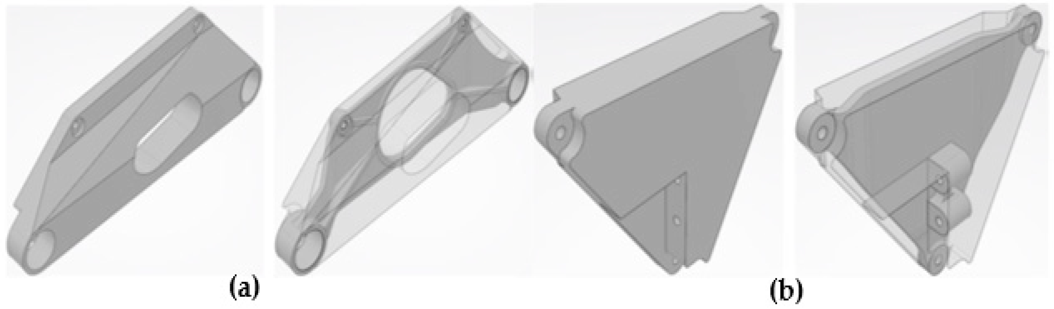
The first step is to create an optimization object. The object can be either an existing component or the maximum allowed building volume, the so-called semi-finished product. In this case, the existing components (design solution after the first iteration) did not meet the strength requirements. Therefore, semi-finished mount bodies were created. A semi-finished product volume is the maximum allowable build volume that a future component can occupy. The design of the semi-finished product is designed to avoid collision with the frame, interior and other components of the passenger car. The designs of the semi-finished mounts and their comparison with the first iterations of the mount design are shown in
Figure 3a,b.
Defining the Functional Elements of the Object for Optimization
Functional elements are those parts of the optimization object volume that are to be preserved after TO. The individual functional elements have been created as separate Bodies. The body shape of the functional elements has a significant impact on the quality of the Mesh and therefore on the progress of the individual simulations that are part of the TO. Therefore, the shapes of the Bodies of the functional elements were designed to follow, roughly, the contour of the shape of the semi-finished product body.
In the case of the front mount, the following functional elements of the object were retained for optimization (
Figure 4a):
Figure 4.
Functional elements of semi-finished products for optimization: (a) front mount, (b) rear mount.
Figure 4.
Functional elements of semi-finished products for optimization: (a) front mount, (b) rear mount.
In the case of the rear mount, the following functional elements of the object were retained for optimization (
Figure 4b):
Creating the Body of the Object for Optimization
By linking the Body of the semi-finished product with the functional element Bodies, the Body of the optimization object was created for use in the next steps of the optimization process. The Partition Design Space function was used to create the Body of the optimization object.
Creating and Assigning a Material Profile to an Optimization Object
In order for a material profile to be usable for TO, three parameters need to be defined:
Density—ρ;
Young’s modulus—E;
Poisson ratio—μ.
For the structural design of the electric motor mounts by the TO method, the AlSi10Mg aluminium alloy was selected, which is suitable for production by DMLS or SLM additive manufacturing technologies. Its parameters are:
Density: ρ = 2650 kg/m3;
Young’s modulus: E = 66 GPa;
Poisson ratio: μ = 0.325;
yield stress: Re = 260 MPa.
2.2.2. TO
The TO process in the SGD module of the 3DExperience CAD software consists of the following sequential steps:
Defining the TO strategy;
Defining the optimization object and its functional elements;
Definition of force loads, constraints and their assignment to individual Load Cases;
Analysis and creation of Mesh;
Initial strength check of the optimization object;
Definition of optimization conditions;
TO;
Concept generation;
Strength check of the generated concepts.
TO Strategy
In the SGD module, the optimization process can be based on different strategies. The TO strategies used are:
Maximize the stiffness for a given part’s weight;
Minimize weight while respecting constraints;
Maximize the value of the lowest natural frequency for a given mass of the part.
For strategies 1 and 3 it is necessary to define the required weight of the optimized part. The disadvantages of these strategies (especially strategy 1) are that the predefined required weight may not be the lowest possible weight of the component at which the strength requirements are met. Optimization by strategy 2 requires the determination of a limiting factor, such as:
The maximum permissible voltage;
The maximum allowable deformation;
The maximum/minimum wall thickness;
The manufacturing technology.
In this strategy, material is removed as long as the optimization conditions of the TO are met [
17].
In the development of the electric motor mounts, the goal was set to achieve the lowest possible weight at which the components met the strength requirements. Therefore, the strategy chosen for TO was No. 2, Minimize weight while respecting specified constraints.
Optimization Object and Its Functional Elements
Before optimization, it is necessary to select which volumes of the object to be optimized are to be preserved and which are to be optimized. The software also informs the user of the masses of the individual volumes. The total weight of the semi-finished front mount is 12.776 kg, of which the weight of the functional volumes is 0.188 kg (1.46%) and the weight of the optimized volume is 12.589 kg (98.54%). The total weight of the semi-finished rear mount is 6.668 kg, of which the weight of the functional volumes is 0.198 kg (2.96%) and the weight of the optimized volume is 6.471 kg (97.04%).
Defining Load Cases
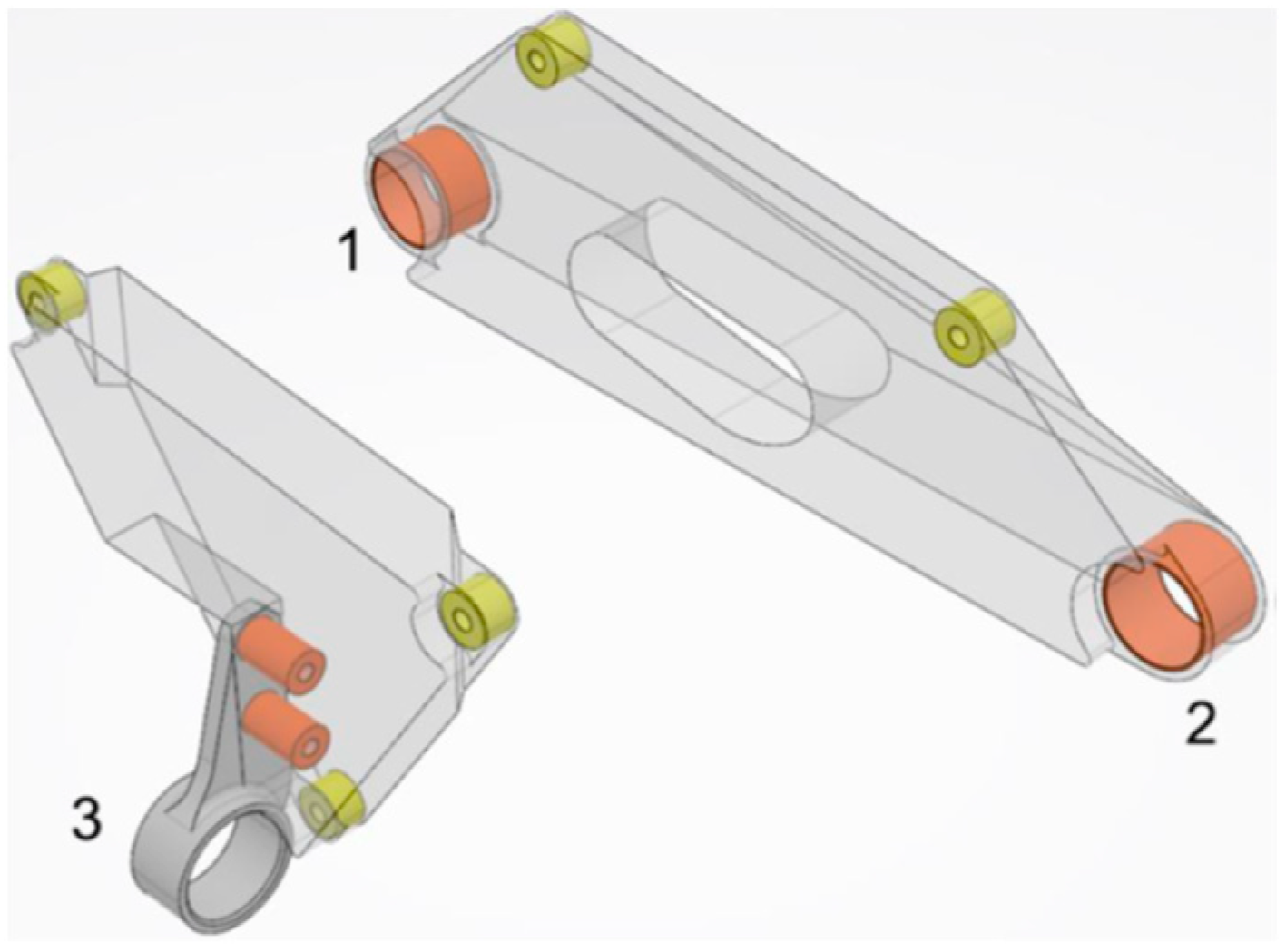
The loads applied to the components were obtained from measurements made on a real vehicle during 30 load situations available from a specific manufacturer. The individual load situations represent conditions that may occur during vehicle handling, driving or collision. The measured forces were in the silentblocks (
Figure 5, positions 1, 2 and 3) through which the electric motor is attached by mounts to the vehicle frame. These forces are then applied to the inner circumference of the front mount bushings and the rear arm bushing, from which the force effects are transferred to the rear mount. All 30 load situations are represented in the software by
Load Cases. A
Load Case consists of the applied force effects (force, moment, …) and constraints.
For the front mount, the
Load Cases include (
Figure 6a):
Figure 6.
Schematic representation of all 30 load cases of semi-finished products (green arrows—the attachment of the mount to the motor, yellow arrows—reactions from the silentblocks): (a) front mount, (b) rear mount.
Figure 6.
Schematic representation of all 30 load cases of semi-finished products (green arrows—the attachment of the mount to the motor, yellow arrows—reactions from the silentblocks): (a) front mount, (b) rear mount.
For the rear mount, the
Load Cases include (
Figure 6b):
Analysis of the Impact of Mesh on the Course and Outcome of the TO and Its Creation
In order to select the right type of Mesh for the above design procedure, it was necessary to find out its influence on the progress and result of the optimization, which was obtained from the analysis of the reference TOs of the given components—the front and rear mounts. For each component, 10 TOs were performed for the 10 most critical Load Cases. The above-mentioned Load Cases were defined on the basis of the analysis of the initial strength control of the semi-finished products consulted with a specific manufacturer. By reducing the number of Load Cases, the aim was to reduce the TO time, which significantly affects the overall development time. The SGD module in the 3DExperience software uses only tetrahedron Mesh in the calculations. This module offers two types of tetrahedron Mesh: linear and quadratic. The elements of each type of tetrahedron Mesh differ in the number of nodal points (the points at which the stress is calculated). The software automatically generates a default Mesh element size (linear or quadratic) so that the total number of elements of the optimization object is approximately 95,000. Therefore, to analyse the effect of Mesh on the progress and outcome of the optimization process, the other eight Mesh configurations available in the software were used, which differed in the types and numbers of elements:
Linear:
- ○
Default number of elements (DEL);
- ○
250,000 elements (250KEL);
- ○
500,000 elements (500KEL);
- ○
750,000 elements (750KEL);
- ○
1 million elements (1000KEL);
Quadratic:
- ○
Default number of elements (DEQ);
- ○
150,000 elements (150KEQ);
- ○
200,000 elements (200KEQ);
- ○
250,000 elements (250KEQ);
- ○
500,000 elements (500KEQ).
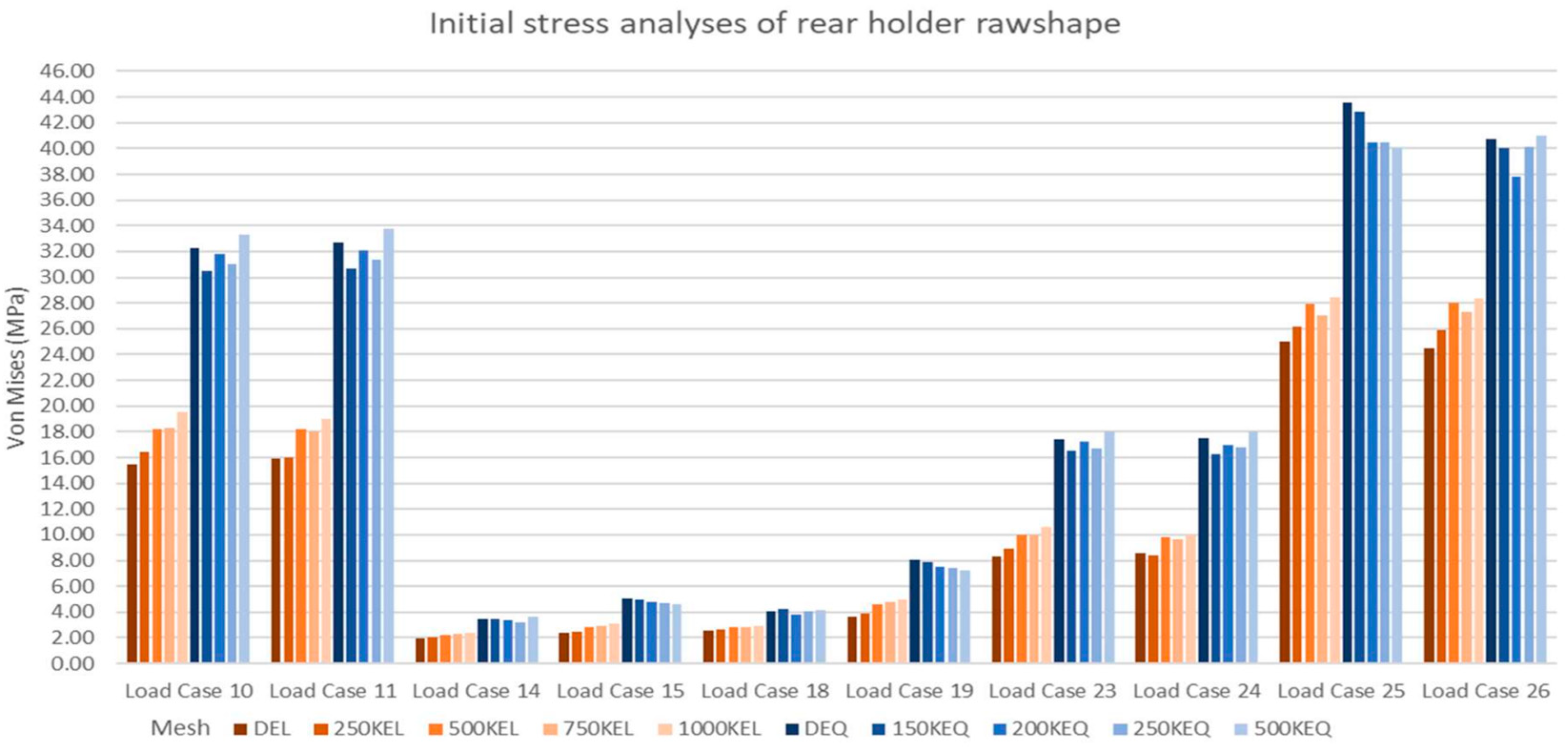
For the analysis, both components were assigned the same AlSi10Mg material, as also defined in Section Creating and Assigning a Material Profile to an Optimization Object. The resulting front and rear mount input strength checks for each
Mesh configuration are presented in
Figure 7 and
Figure 8.
From the graphs (
Figure 7 and
Figure 8), the effect of
Mesh on the quality of the initial strength check results is evident.
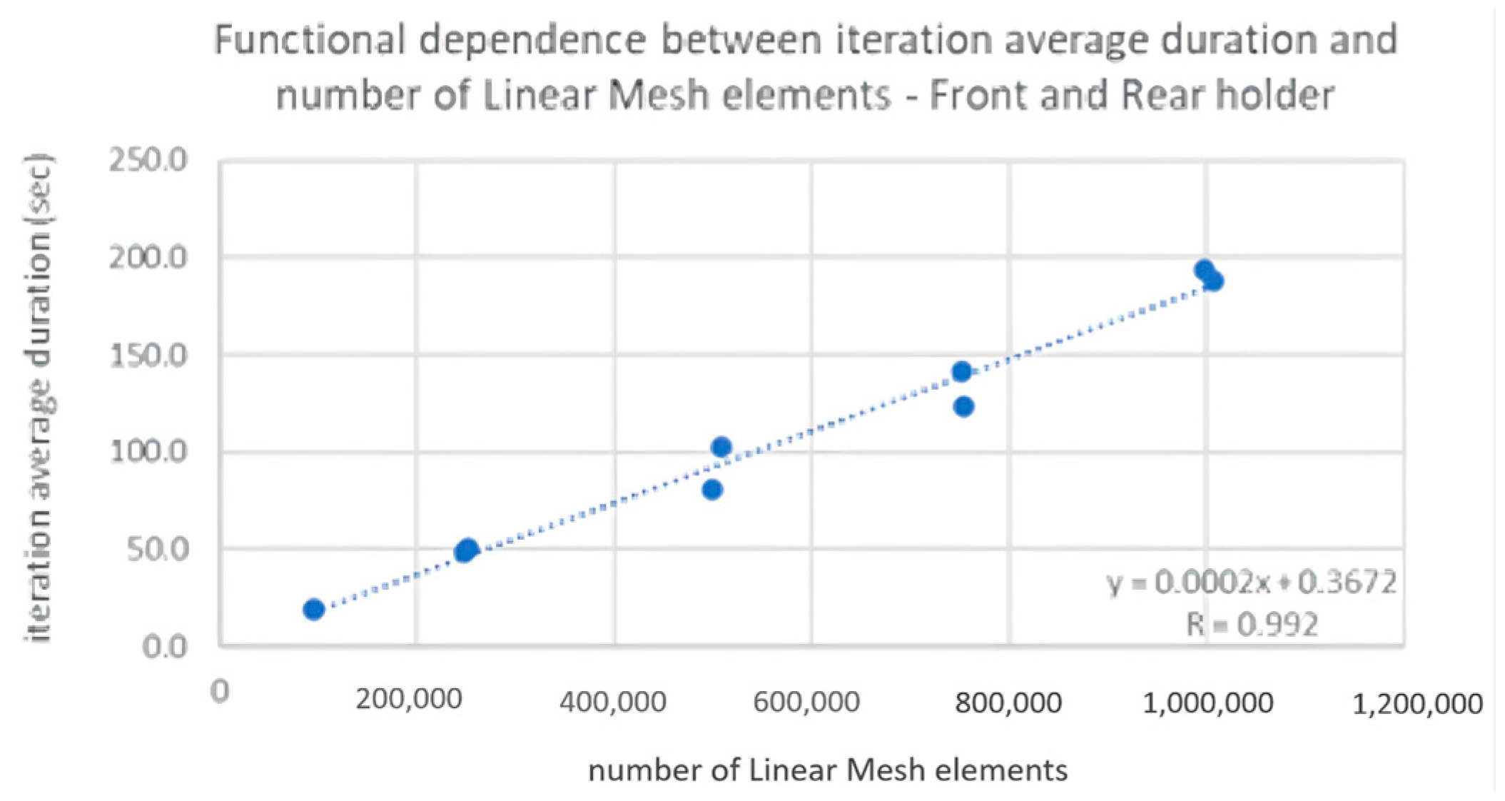
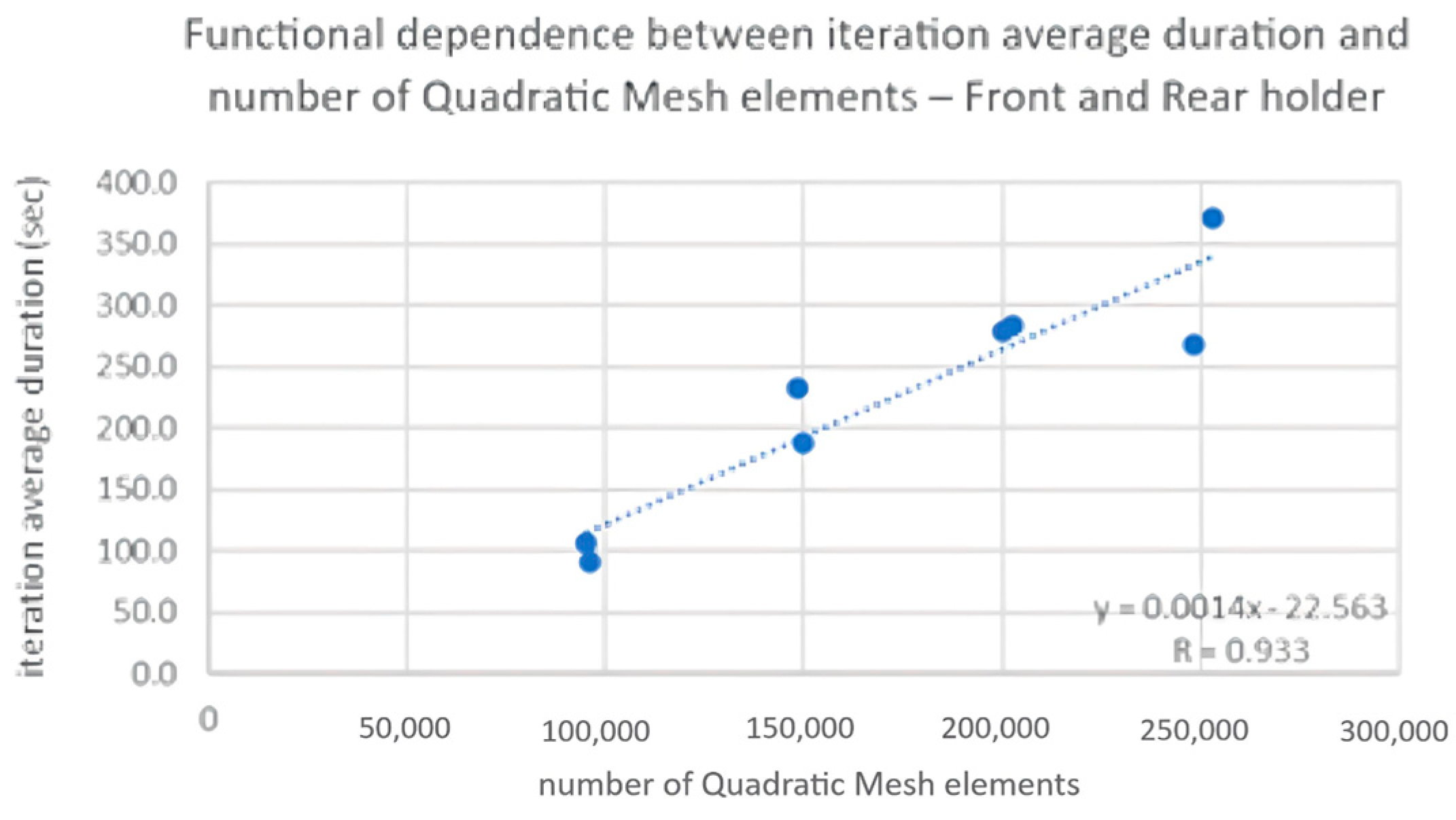
A combination of measured data from both components was used to define the functional dependence of the average time of topological iterations and the number of elements. The quadratic
Mesh 500KEQ configuration was omitted prior to running TO due to the inadequate duration of the simulations. The functional dependencies between the average duration of one topological iteration and the number of elements of the linear and quadratic
Mesh are shown in
Figure 9 and
Figure 10.
The analysis showed that the configuration of
Mesh significantly affects the progress and results of TO. Optimization with the linear
Mesh configuration with the default number of elements takes less time. The optimization time then increases in direct proportion to the number of elements (
Figure 9), along with the quality of the obtained results. Optimization with quadratic
Mesh takes significantly longer (
Figure 10), although the obtained results are of significantly higher quality.
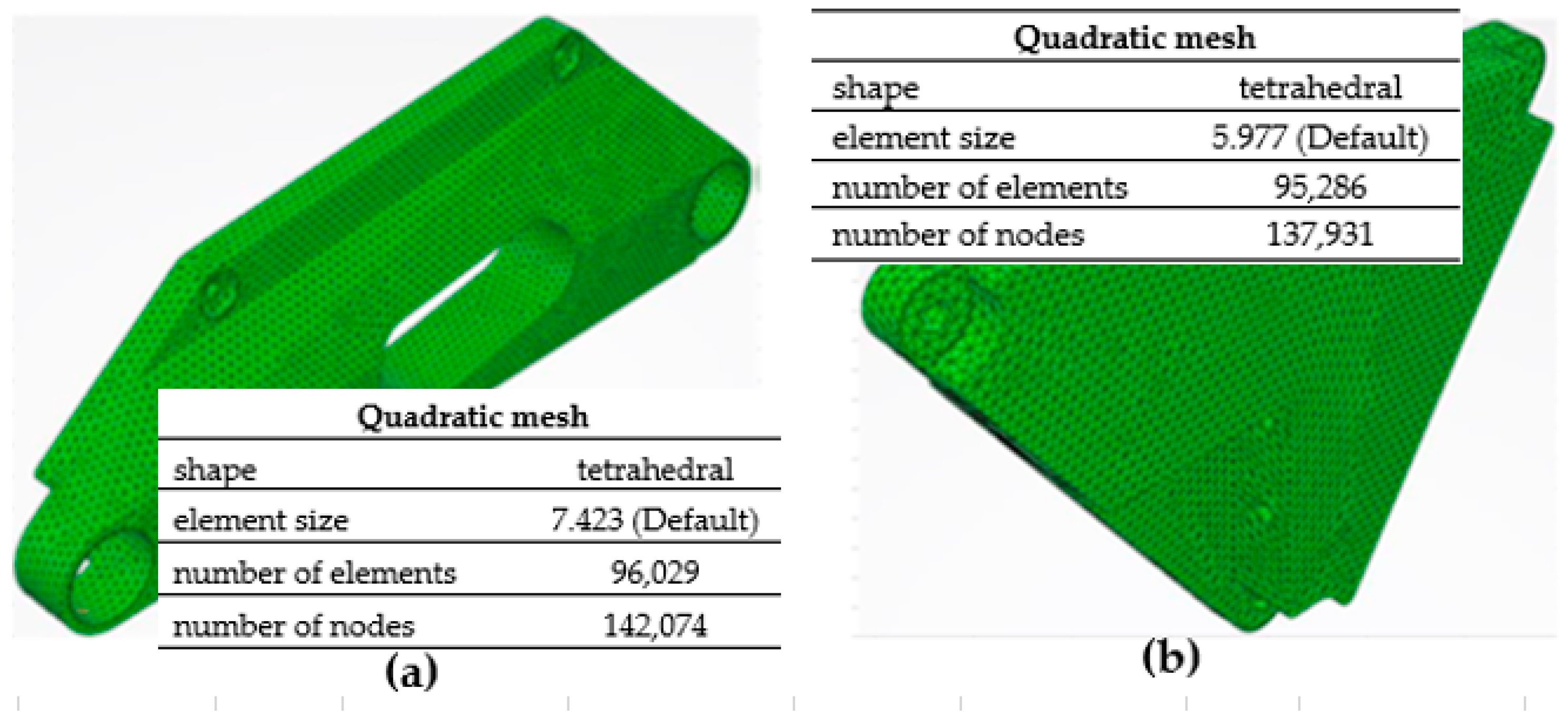
Based on the results obtained from the analysis of the impact of the
Mesh on the TO progress and outcome and the objectives set, the
Automatically deducing quadratic mesh option was used for both mounts. The quadratic
Mesh with the default number of elements of the front mount is shown in
Figure 11a and the rear mount in
Figure 11b. The shapes of the functional elements’
Bodies were designed to follow the contours of the shape of the semi-finished product with a certain distance to avoid certain qualitative errors of the
Mesh.
Initial Strength Check of the Object for Optimization
The initial strength check is used to demonstrate the optimization potential of the object to be optimized. Its result serves as input to the TO. Based on the stress map, the material is removed or reorganized in the volume of the semi-finished product. The value of the maximum stress from the input strength check must be lower than the value of the allowable stress in the optimization condition (Section Defining Optimization Conditions). For the initial strength check and subsequently throughout the TO process, the 10 most unfavourable Load Cases were worked with.
Defining Optimization Conditions
A single optimization condition, i.e., the maximum allowable stress, was defined for the TO of the electric motor mounts. In order to be able to start the optimization process at all, the value of the maximum allowable stress must be greater than the stress values obtained in the initial strength check of the semi-finished product. On the other hand, it should not be greater than the yield strength or ultimate strength of the material used. On the basis of consultations with companies using SLM additive technology for the production of dynamically stressed mobile machine components made of AlSi10Mg aluminium alloy, it was found that the maximum stress value (reduced Von Mises stress) of the static strength analysis should be in the range of 90–110 MPa. Compliance with this condition will achieve the required service life of the components. As an optimization condition for the TO of both motor mounts, a value of 100 MPa of maximum allowable stress was set.
TO
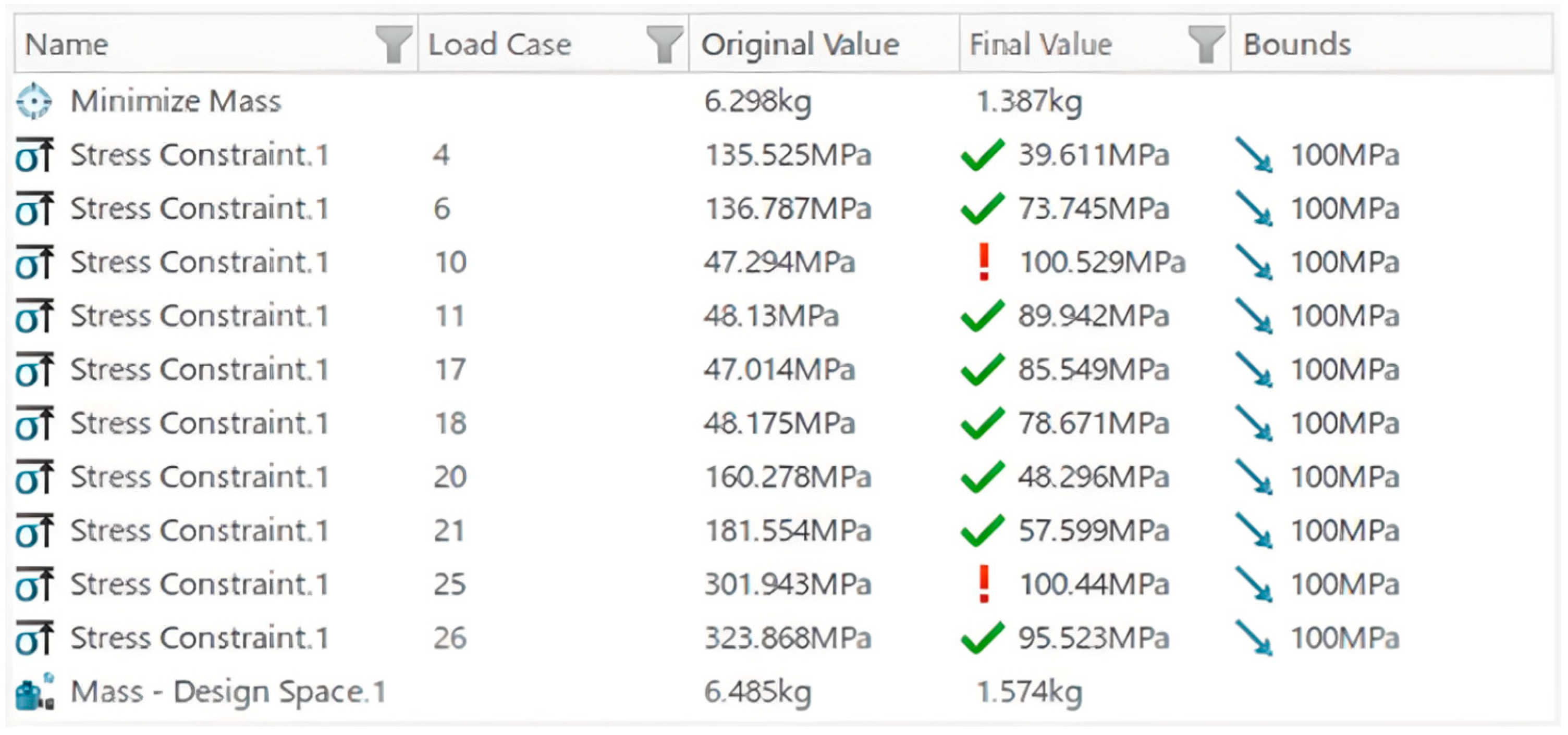
The TO of the front mount took 3 h and 2 min. The optimization converged to a solution that satisfied the optimization constraints after 120 topological iteration cycles were performed. The results of the TO of the front mount are shown in
Figure 12. The software evaluated the failure to meet the optimization requirement for two
Load Cases. The stress values exceeded the maximum allowable stress value by 0.5%. However, after analysing the results, it was concluded that the optimization condition was satisfied in all 10
Load Cases. The achieved mass of the front mount concept was 1.574 kg (
Figure 12, labelled as
Mass—Design Space.1: Final Value), i.e., 12.3% of the weight of the semi-finished product.
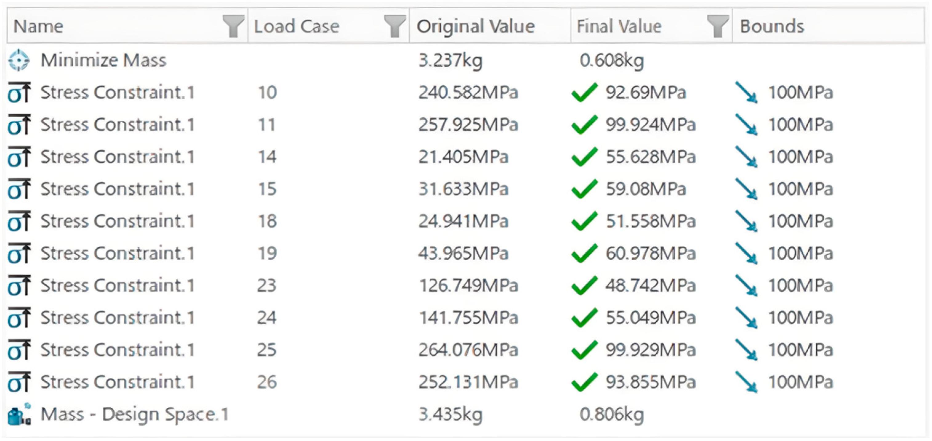
The TO of the rear mount lasted 1 h and 32 min. In this case, the optimization converged to a solution that satisfied the optimization conditions after only 52 iteration cycles had been performed. The results of the TO of the rear mount are shown in
Figure 13. The optimization condition was satisfied in all
Load Cases. The achieved mass of the rear mount was 0.806 kg (
Figure 13, labelled as
Mass—Design Space.1: Final Value), i.e., 12.1% of the mass of the semi-finished product.
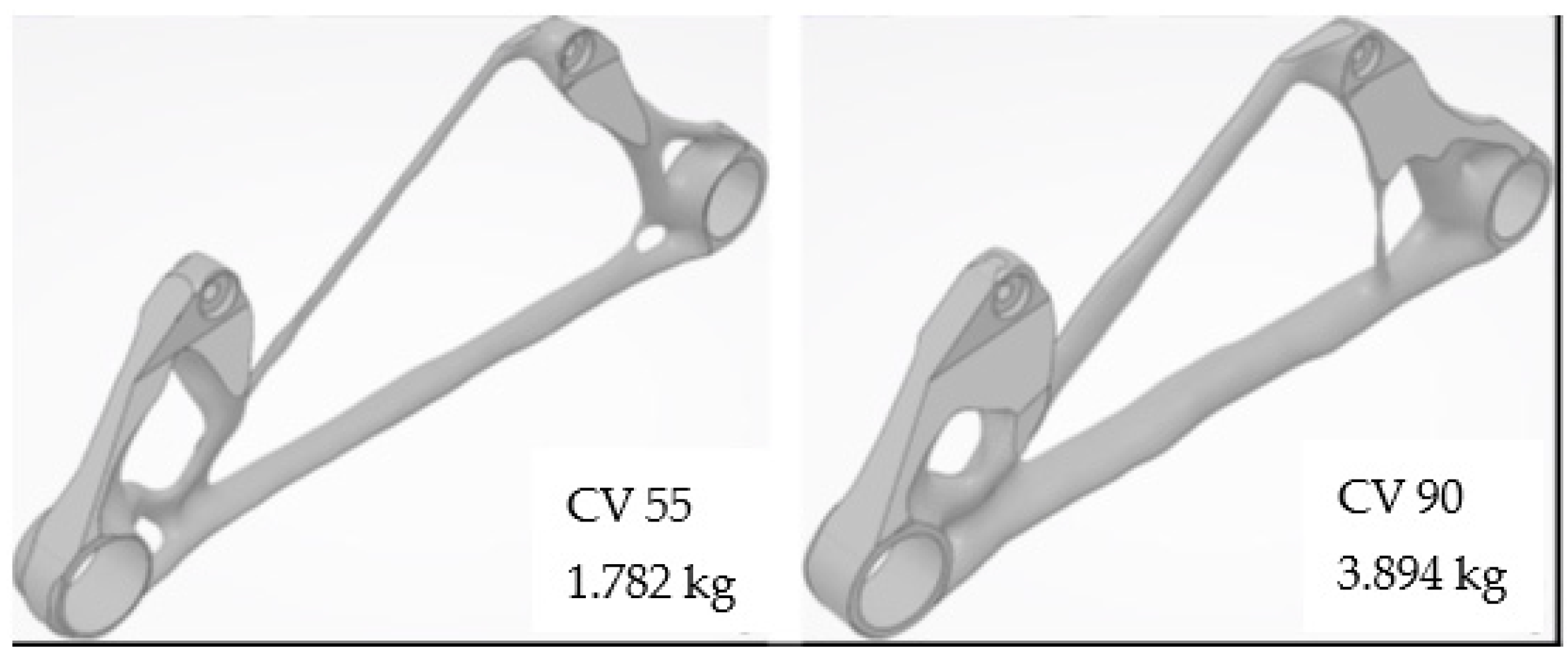
Concept Generation
The concept generation process is used to materialize the results of the TO. The
Cutting Value (CV) parameter has the greatest influence on the generated shape. It is an informative parameter whose value describes the amount of mass retained after the optimization process. By changing the parameter, material is removed or added with respect to the TO result. Two concepts have been generated for the two mounts. One concept was generated with a CV parameter such that its mass was closest to the mass of the concept after the last iteration of the TO (
Figure 12 and
Figure 13, labelled as
Mass—Design Space.1: Final Value). The CV value of the front mount was set to 55 (
Figure 14) and that of the rear mount to 53 (
Figure 15). The second concept was generated with a higher CV parameter value (CV value: front mount—90, rear mount—80,
Figure 14 and
Figure 15). The generation of two concepts with different values of the CV parameter allowed the influence of the parameter on the weight, the design concept and the strength of the generated concepts to be analysed. From
Figure 14 and
Figure 15 it can be seen that the weight of the generated concepts with the CV parameter, where the weight is closest to the weight after the last iteration of the TO, is greater than that shown in
Figure 12 and
Figure 13. This is because the software adds material in certain places in order to generate a concept with a nice continuous shape without defects (no sharp creases in the surfaces).
Strength Checks of Generated Concepts
Strength checks of the generated semi-finished front and rear mount concepts for all 10 Load Cases were used to validate the strength of their design and the accuracy of the TO results.
The raw generated front mount concept with CV 55 did not meet the strength requirements for all Load Cases (two Load Cases). However, after analysis of the results, it was concluded that, with minor modifications to the design in postprocessing, these relatively high stresses could be avoided. The strength checks proved the accuracy of the TO results. The concepts generated are suitable for use as templates for the creation of the final design of the components within the postprocessing.
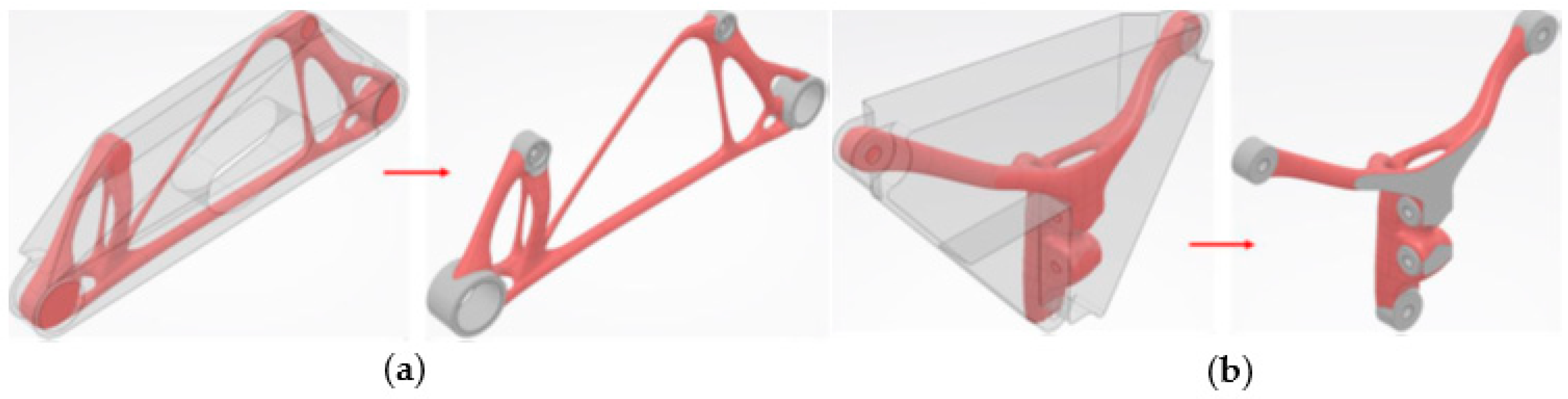
2.2.3. Postprocessing—Creation of the Final Design
As part of the postprocessing, the complicated design of the generated and validated concepts is reconstructed, and functional elements are implemented in the final design.
The SGD module has features and tools for reconstructing complex geometry through
NURBS surfaces [
18]. These are general surfaces whose geometry is controlled by control points. Such surfaces can be connected to each other to form larger units, thus creating the final design of the component. The individual design elements of the concepts are modelled as separate planar entities by the
IMA—Tube drawing and
IMA—Cylinder functions. The final design of the front and rear mount was obtained by trimming the semi-finished products of mounts with the final
NURBS surfaces by using the
Split function and implementing the functional elements into the trimmed volume by
Boolean operations (
Figure 16a,b).
2.2.4. Validation of the Final Design
To validate the correctness of the final front and rear mount design, strength checks were performed for all 30 Load Cases. Linear Mesh with an element size of 2 mm was used for the front mount and linear Mesh with an element size of 1.5 mm was used for the rear mount. These are the same Mesh configurations that were used in the validation of the generated mount concepts (Section Strength Checks of Generated Concepts). The strength checks proved the correct design of the front and rear electric motor mounts. In neither Load Case did the stresses (Von Mises type) exceed the maximum allowable stress of 100 MPa. All the conditions imposed on the design of the mount structure were fulfilled.
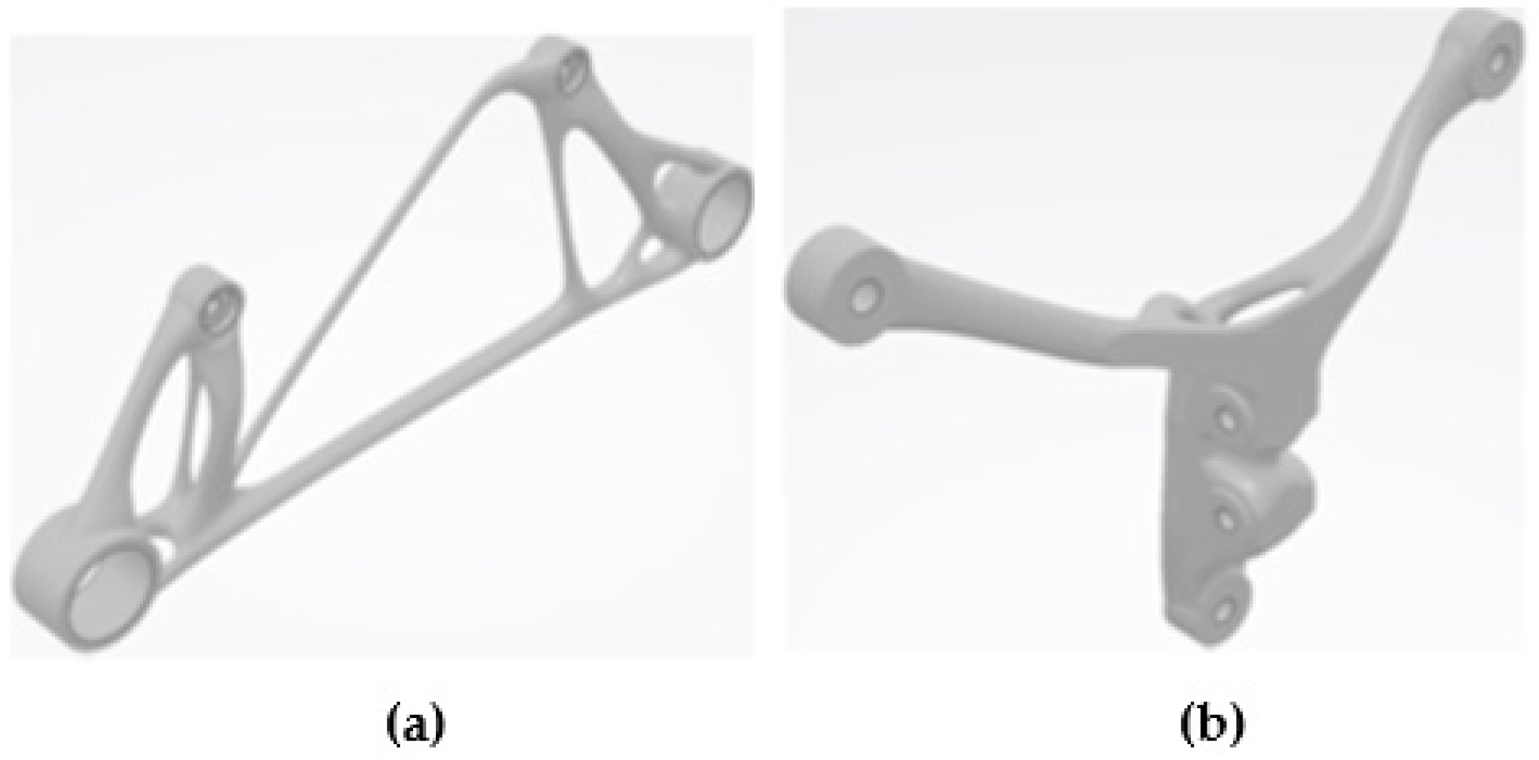
2.2.5. Final Design—Preparation for 3D Printing
The weight of the final design of the optimized front mount is 1.714 kg. A detailed view of the front motor mount design is shown in
Figure 17a. The weight of the final design of the rear mount is 0.783 kg. A detailed view of the electric motor rear mount design is shown in
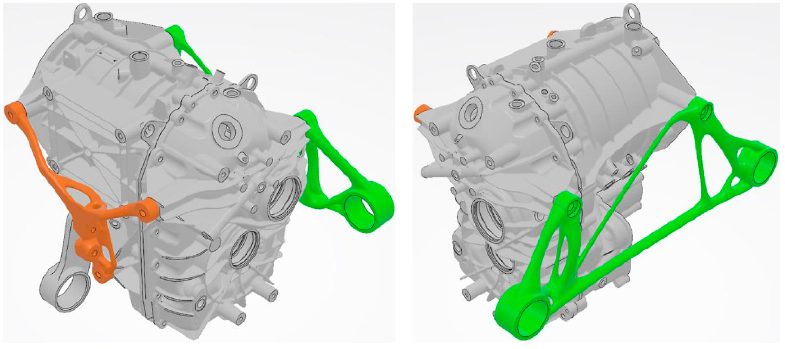
Figure 17b. The electric motor assembly with optimized front and rear mounts is shown in
Figure 18.
Before the actual additive manufacturing with SLM technology, it is necessary to perform 3D printing and cooling simulation of the component. This will highlight the behaviour of the components during the entire manufacturing process. Based on the results, manufacturing inaccuracies can be predicted and then eliminated by changing the design (so called component predeforming) or eliminated in the manufacturing finishing operations. Areas that are prone to deformation during 3D printing or during cooling after the manufacturing process shall be reinforced with supports. These supports are then removed mechanically or by vibration. Additional material shall be applied to functional surfaces, which are subject to high demands in terms of precision and roughness. Precision chip machining is used to remove the additive and thus achieve the required precision and roughness of the functional surfaces.
3. Results
Table 1 shows the durations of the different stages of the development of the design of the electric motor mounts by the TO method using
3DExperience software. These are the times that can be achieved with ideal inputs, ideal software performance and ideal outputs from the optimization process. However, real-world use has shown that it is often necessary to redesign inputs (semi-finished product, partitions) to improve the input strength optimization results, and it is often necessary to change the optimization conditions to ensure that the optimization process is working properly and thus to obtain usable concepts for the optimized parts. This nature of the software and the TO method itself is accounted for by the reliability coefficient
ks𝜖〈1,3〉. The coefficient interval was defined based on the experience gained by applying the method and software to the development of several components along with consultation with the manufacturer. A comparison of the development time of electric motor mounts with the TO method and the development time with traditional design methods is shown in
Table 2.
Theorem 1. The given hypothesis deals with the reduction of the design time in the development process along with the reduction of weights and preservation of the required properties of the components of a certain product line by the application of the mentioned DfAM (TO) method compared to the traditional design methods.
Proof of Theorem 1. It is clear that the implementation of the TO method into the process of designing the optimal design of electric motor mounts has significantly reduced the development time. A weight saving was also achieved over the first iteration of the design of the electric motor mounts, which additionally did not pass the strength check (
Table 2). □
4. Discussion
The application of the proposed design methodology in practice confirmed its effectiveness at the component development stage. To a large extent, the results and the proposed methodology were positively influenced by the Mesh analysis. The implementation of the given procedure in the component design process demonstrated significant savings in development time and component weight with AM orientation. From this, other conclusions are drawn that the departure from traditional design methods or the use of innovative approaches has a significant impact on the overall development. Of course, it cannot be forgotten that the use of advanced design methods and their development is greatly influenced by the production method. AM and DfAM have a directly proportional progress and development curve. The methodology in question is relevant and significant results are only achievable when using AM, as it is not possible to exploit the maximum potential of DfAM (TO) with conventional manufacturing technologies.
Important questions include why TO principles are not used extensively in design and why the procedures are not used extensively in practice, as they are long-known methods of design. This is due to the relatively difficult operation of optimization software, its reliability and the lack of trained and experienced personnel. Another cause or constraint is the lack of production lines using AM and the price range of products in high-volume production. The aim of this research was to prove the effectiveness of the proposed design solution, as mentioned above, and its implementation in practice to reduce the mentioned negative factors, especially in terms of trained personnel and operator mastery.
Another research activity is the development of variant design methodologies tailored for the design process of specific product lines, as each component and part exhibits different factors affecting the effectiveness of the design process and its procedures.
5. Conclusions
Based on the knowledge gained, the validation of the proposed procedures and the definition of the DfAM methodology, it is possible to confirm the benefits for the scientific field, practice and education. This area of research has great potential and, with continued progress, its importance will increase with further results achieved.
A contribution to the scientific discipline is the compilation of a design methodology (DfAM, TO), the results of which have confirmed its effectiveness when implemented in AM. This procedure serves as a template for further development and innovation in the research area, whether by specifying a different type of AM or even a different type of manufacturing technology.
The above solution to the problem is of considerable importance for practice when used in the design process. The intention of most industrial companies is to reduce costs, not only for production but also for development. With the saved design time and reduced component weights from the research results, possible financial savings have been confirmed by the manufacturer of the components in question. However, it should be stressed that not every field of practice is amenable to the aforementioned procedure with regard to AM or DfAM.
With further research and innovations, and especially by broadening the range of applications of the methodology, its application in education could also increase significantly. The methodology is so far specified only for one direction of development and for a certain type of production, which does not, however, preclude its use as a material for the preparation of educational procedures in training workplaces.
Author Contributions
Conceptualization, P.H. and M.N. (Martin Nagy); methodology, L.G. and A.K.; software, A.K. and M.N. (Miroslav Nagy); validation, P.H. and V.C.; formal analysis, P.H. and M.N. (Martin Nagy); investigation, L.G. and V.C.; resources, V.C.; data curation, M.N. (Miroslav Nagy); writing—original draft preparation, P.H. and M.N. (Martin Nagy); writing—review and editing, P.H. and L.G.; visualization, V.C.; supervision, L.G.; project administration, L.G.; funding acquisition, L.G. All authors have read and agreed to the published version of the manuscript.
Funding
This research received no external funding.
Institutional Review Board Statement
Not applicable.
Informed Consent Statement
Not applicable.
Data Availability Statement
The data presented in this study are available on request from the corresponding authors.
Conflicts of Interest
The authors declare no conflict of interest.
References
- Liu, J.; Gaynor, A.T.; Chen, S.; Kang, Z.; Suresh, K.; Takezawa, A.; Li, L.; Kato, J.; Tang, J.; Wang, C.C.L. Current and future trends in topology optimization for additive manufacturing. Struct. Multidiscip. Optim. 2018, 57, 2457–2483. [Google Scholar] [CrossRef]
- Mazurkievic, I.; Gulan, L.; Izrael, G. Mobilné Pracovné Stroje: Teória a Konštrukcia Základných Modulov; Nakladateľstvo STU: Bratislava, Slovakia, 2013; 301p. [Google Scholar]
- Chadha, U.; Abrol, A.; Vora, N.P.; Tiwari, A.; Shanker, K.S.; Selvaraj, S.K. Performance evaluation of 3D printing technologies: A review, recent advances, current challenges, and future directions. Prog. Addit. Manuf. 2022, 7, 853–886. [Google Scholar] [CrossRef]
- Jagadeesh, P.; Puttegowda, M.; Rangappa, S.M.; Karfidov, A.; Gorbatyuk, S.; Anish, K.; Mrityunjay, D.; Siengchin, S. A comprehensive review on 3D printing advancements in polymer composites: Technologies, materials, and applications. Int. J. Adv. Manuf. Technol. 2022, 121, 127–169. [Google Scholar] [CrossRef]
- Kumar, S.; Gopi, T.; Harikeerthana, N.; Gupta, M.K.; Gaur, V.; Krolczyk, G.M.; Wu, C. Machine learning techniques in additive manufacturing: A state of the art review on design, processes and production control. J. Intell. Manuf. 2023, 34, 21–55. [Google Scholar] [CrossRef]
- Tang, Y.; Zhao, Y.F. A survey of the design methods for additive manufacturing to improve functional performance. Rapid Prototyp. J. 2016, 22, 569–590. [Google Scholar] [CrossRef]
- Lampeas, G. Revolutionizing Aircraft Materials and Processes; Pantelakis, S., Tserpes, K., Eds.; Springer Nature: Cham, Switzerland, 2020; 405p. [Google Scholar]
- Jun, Z.; Yuechao, Z.; Zhenyu, F. Topology optimization for additive manufacturing with self-supporting constraint. Struct. Multidiscip. Optim. 2021, 63, 2341–2353. [Google Scholar]
- Meng, L.; Zhang, W.; Quan, D.; Shi, G.; Tang, L.; Hou, Y.; Breitkopf, P.; Zhu, J.; Gao, T. From Topology Optimization Design to Additive Manufacturing: Today’s Success and Tomorrow’s Roadmap. Arch. Comput. Methods Eng. 2020, 27, 805–830. [Google Scholar] [CrossRef]
- FE Training. Available online: https://www.fetraining.net/topology-optimization-part-1/ (accessed on 18 September 2023).
- Berselli, G.; Bilancia, P.; Luzi, L. Project-based learning of advanced CAD/CAE tools in engineering education. Int. J. Interact. Des. Manuf. 2020, 14, 1071–1083. [Google Scholar] [CrossRef]
- Bertoni, M.; Bertoni, A. Iterative value models generation in the engineering design process. Des. Sci. 2019, 5, 22. [Google Scholar] [CrossRef]
- Zegard, T.; Paulino, G.H. Bridging topology optimization and additive manufacturing. Struct. Multidiscip. Optim. 2016, 53, 175–192. [Google Scholar] [CrossRef]
- Mirzendehdel, A.M.; Suresh, K. Support structure constrained topology optimization for additive manufacturing. Comput.-Aided Des. 2016, 81, 1–13. [Google Scholar] [CrossRef]
- Nieto, D.M.; Sánchez, D.M. Design for Additive Manufacturing: Tool Review and Case Study. Appl. Sci. 2021, 11, 1571. [Google Scholar] [CrossRef]
- Baotong, L.; Wenhao, T.; Senmao, D.; Jun, H. A generative design method for structural topology optimization via transformable triangular mesh (TTM) algorithm. Struct. Multidiscip. Optim. 2020, 62, 1159–1183. [Google Scholar]
- Sun, H.; Ma, L. Generative Design by Using Exploration Approaches of Reinforcement Learning in Density-Based Structural Topology Optimization. Designs 2020, 4, 10. [Google Scholar] [CrossRef]
- Gulanová, J.; Lonek, S.; Gulan, L. Comparison of two different approaches of a class-A surface creation and quality verification. Comput.-Aided Des. Appl. 2018, 15, 757–763. [Google Scholar] [CrossRef]
Figure 1.
Topology optimization of the part [
10].
Figure 1.
Topology optimization of the part [
10].
Figure 2.
First iteration of the design solution for electric motor mounts (green—front mount, orange—rear mount).
Figure 2.
First iteration of the design solution for electric motor mounts (green—front mount, orange—rear mount).
Figure 3.
Object for optimization: (a) front semi-finished mount and design solution after the first iteration, (b) rear semi-finished mount and its design solution after the first iteration.
Figure 3.
Object for optimization: (a) front semi-finished mount and design solution after the first iteration, (b) rear semi-finished mount and its design solution after the first iteration.
Figure 5.
Bushings for the silentblocks of the semi-finished front mount (1,2) and rear mount (3).
Figure 5.
Bushings for the silentblocks of the semi-finished front mount (1,2) and rear mount (3).
Figure 7.
Initial stress analyses of front semi-finished mount.
Figure 7.
Initial stress analyses of front semi-finished mount.
Figure 8.
Initial stress analyses of rear semi-finished mount.
Figure 8.
Initial stress analyses of rear semi-finished mount.
Figure 9.
Functional dependence between iteration average duration and number of linear Mesh elements—front and rear mounts.
Figure 9.
Functional dependence between iteration average duration and number of linear Mesh elements—front and rear mounts.
Figure 10.
Functional dependence between iteration average duration and number of quadratic Mesh elements—front and rear mounts.
Figure 10.
Functional dependence between iteration average duration and number of quadratic Mesh elements—front and rear mounts.
Figure 11.
Quadratic Mesh with default number of elements: (a) semi-finished front mount, (b) semi-finished rear mount.
Figure 11.
Quadratic Mesh with default number of elements: (a) semi-finished front mount, (b) semi-finished rear mount.
Figure 12.
Results of the TO of the semi-finished front mount.
Figure 12.
Results of the TO of the semi-finished front mount.
Figure 13.
Results of the TO of the semi-finished rear mount.
Figure 13.
Results of the TO of the semi-finished rear mount.
Figure 14.
Generated front mount concepts.
Figure 14.
Generated front mount concepts.
Figure 15.
Generated rear mount concepts.
Figure 15.
Generated rear mount concepts.
Figure 16.
Trimming of the semi-finished (a) front and (b) rear mount with the final NURBS surface and implementation of the functional elements.
Figure 16.
Trimming of the semi-finished (a) front and (b) rear mount with the final NURBS surface and implementation of the functional elements.
Figure 17.
Final design of the optimized electric motor mount: (a) front and (b) rear.
Figure 17.
Final design of the optimized electric motor mount: (a) front and (b) rear.
Figure 18.
Electric motor with optimized mounts (green—front mount, orange—rear mount).
Figure 18.
Electric motor with optimized mounts (green—front mount, orange—rear mount).
Table 1.
Development time of electric motor mounts by TO method.
Table 1.
Development time of electric motor mounts by TO method.
| Development Time of Electric Motor Mounts by Topological Optimization Method |
|---|
| Stages | Job Description | Front Mount | Rear Mount |
|---|
| Time (h) |
|---|
| pre-preparation for topological optimization | Section 2.2.1 | 3 | 3 |
| topology optimization | Sections TO Strategy, Optimization Object and Its Functional Elements | 0.25 | 0.25 |
| Sections Defining Load Cases, Analysis of the Impact of Mesh on the Course and Outcome of the TO and Its Creation, Initial Strength Check of the Object for Optimization | 2 | 2 |
| Sections Defining Optimization Conditions, TO | 3 | 1.5 |
| Sections Concept Generation, Strength Checks of Generated Concepts | 1 | 1 |
| postprocessing | Section 2.2.3 | 4 | 4 |
| validation of the final design | Section 2.2.4 | 1 | 1 |
| preparation for production | Section 2.2.5 | 1 | 1 |
total development time under ideal conditions
(rounded to whole hours) | 15 | 14 |
| method reliability coefficient ks | 3 |
| total development time under realistic conditions | 46 | 41 |
Table 2.
Comparison of design methods for the development of electric motor mounts.
Table 2.
Comparison of design methods for the development of electric motor mounts.
| Comparison of Design Methods |
|---|
| Method of Construction | Development Time (h) | Weight of Mounts (kg) |
|---|
| Ideal Conditions | Real Conditions |
|---|
Front
Mount | Rear
Mount | Front
Mount | Rear
Mount | Front
Mount | Rear
Mount |
|---|
| traditional (Section 2.1) | 75 | 1.9 | 1.124 |
| TO (Table 1, Section 2.2) | 15 | 14 | 46 | 41 | 1.714 | 0.783 |
| savings when using TO | 80% | 82% | 39% | 45% | 10% | 30% |
| Disclaimer/Publisher’s Note: The statements, opinions and data contained in all publications are solely those of the individual author(s) and contributor(s) and not of MDPI and/or the editor(s). MDPI and/or the editor(s) disclaim responsibility for any injury to people or property resulting from any ideas, methods, instructions or products referred to in the content. |
© 2023 by the authors. Licensee MDPI, Basel, Switzerland. This article is an open access article distributed under the terms and conditions of the Creative Commons Attribution (CC BY) license (https://creativecommons.org/licenses/by/4.0/).


 ,
, 


