
Suitability of Dual-Band, Dual-Polarized Patch Antennas with a Superstrate for the Miniaturization of Ku-Band Antenna Arrays for Automotive Applications


Abstract
:1. Introduction
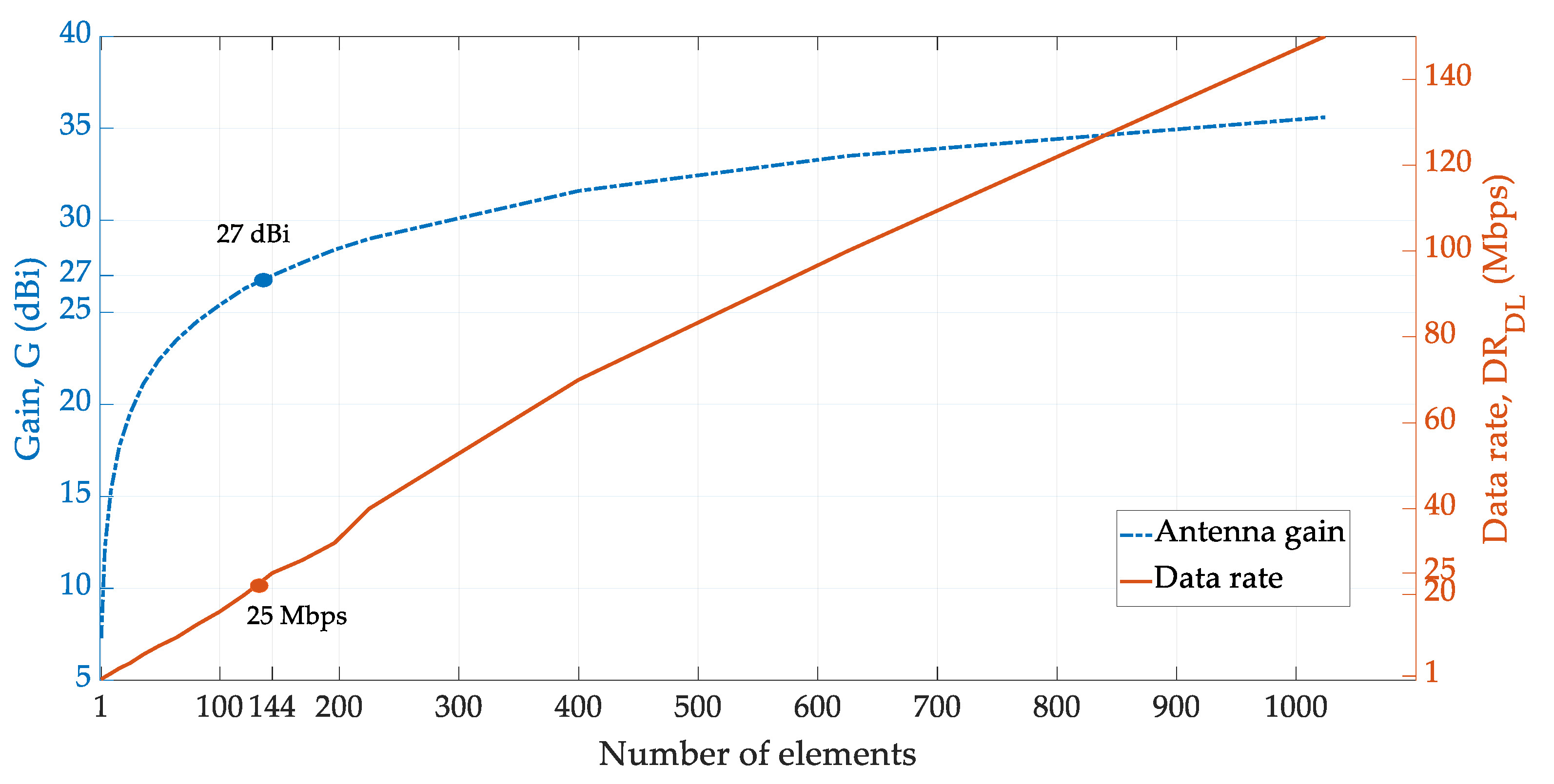
- The calculation of the LEO satellite link budget, which establishes a general relationship between any desired data rate in downlink and the corresponding antenna gain necessary for achieving the same. Several other authors [9,10,11] discuss Ku-band antennas (with frequency range of 12 to 18 GHz and wavelengths of 1.7 to 2.5 cm) and the corresponding link budgets. In this paper, the link budget for broadband internet data rates DR >25 Mbps are consolidated for LEO connectivity in Section 2.
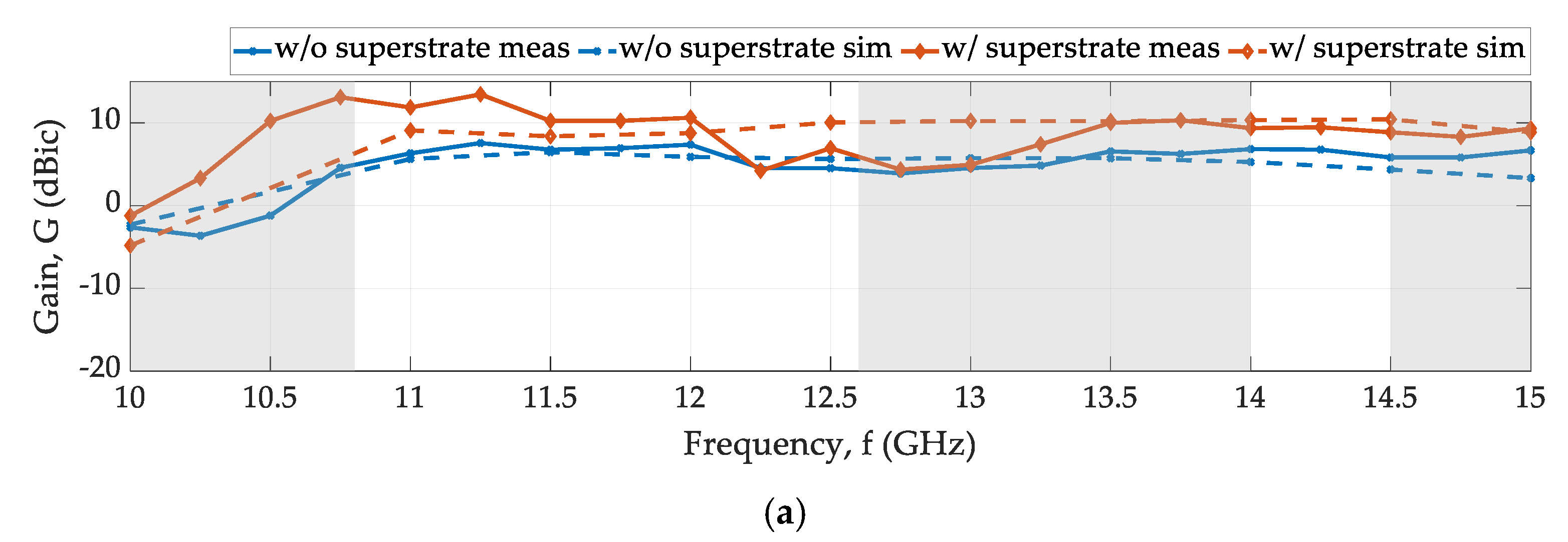
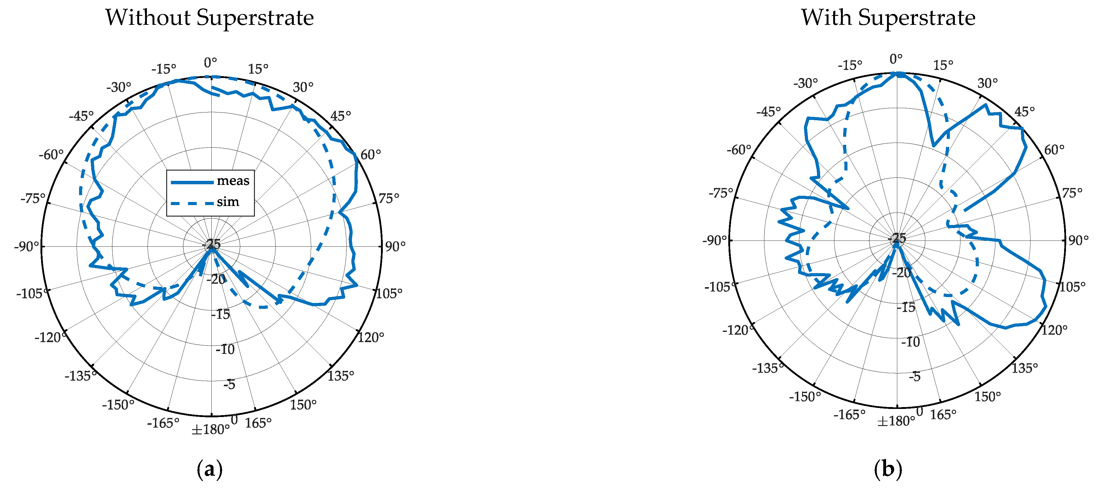
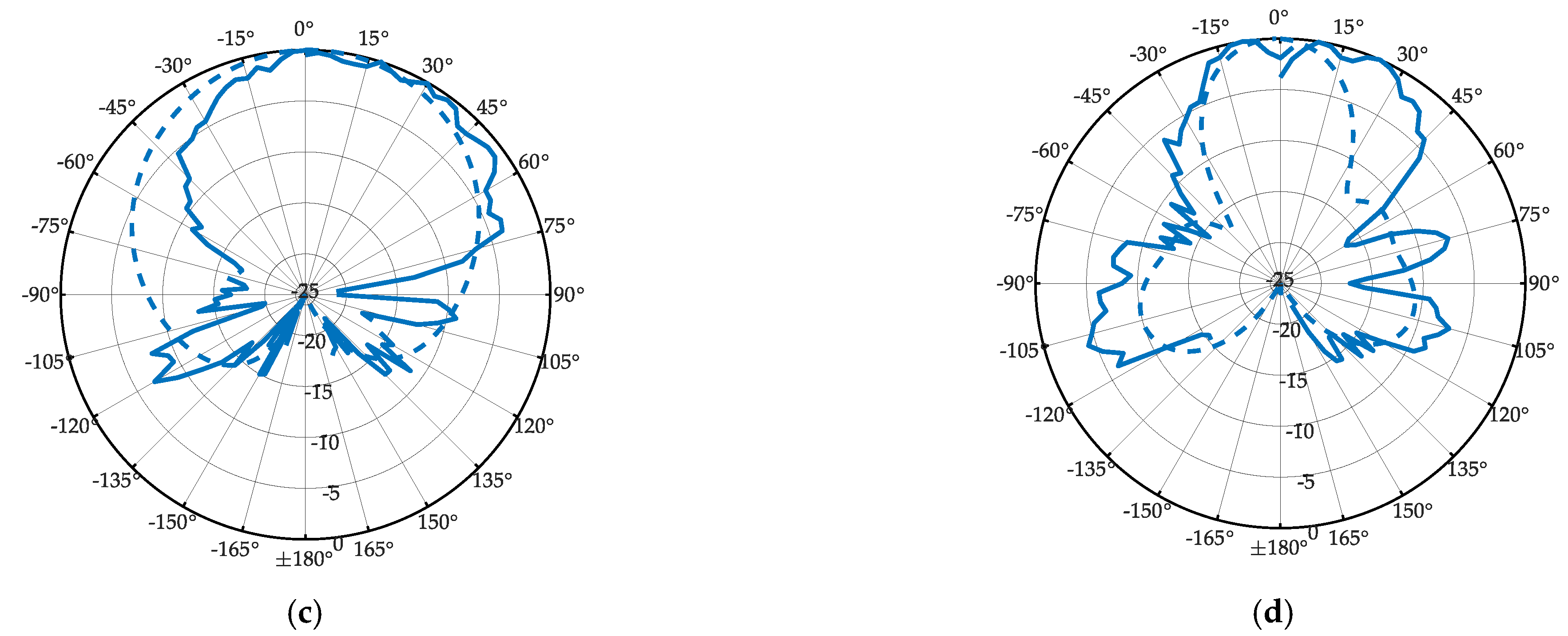
- The simulation and measurement results for the proposed single antenna element with and without superstrate loading are presented and discussed. With the superstrate, the single-element gain was enhanced by more than 3 dB, which has significant consequences for the potential miniaturization of the Ku-band array antenna in that theoretically, the array size could be halved compared to an array without superstrate loading. These results are elucidated in Section 3. Section 4 presents the conclusion and the future work.
2. Antenna Array Specifications Based on Link Budget for LEO Connectivity
3. Proposed Antenna
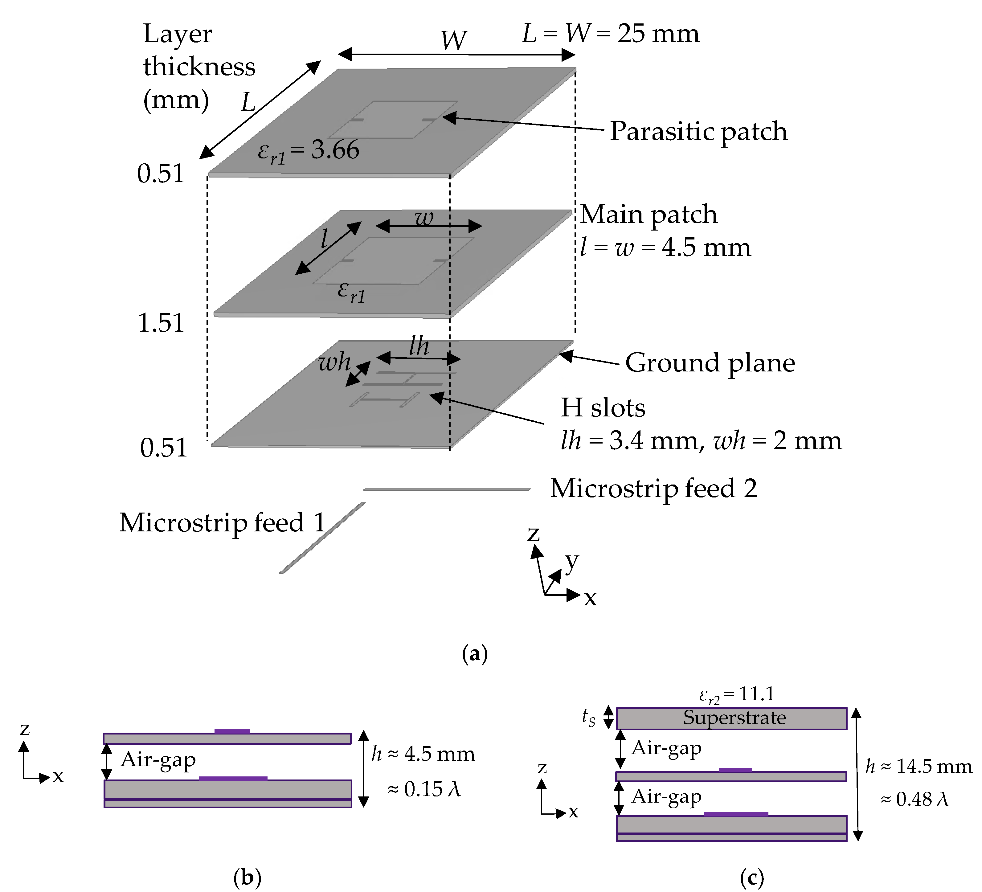
3.1. Design
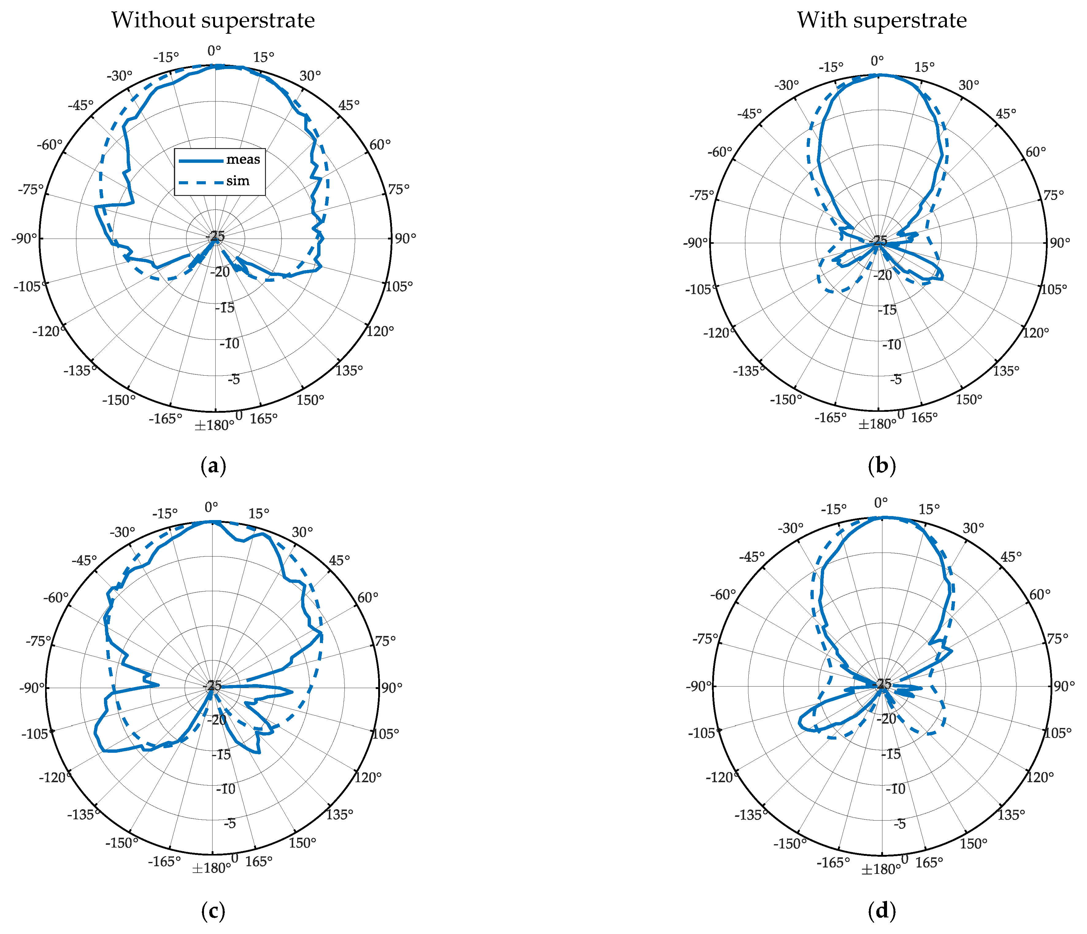
3.2. Measurement Results with and without the Superstrate
4. Conclusions
- The behavior of a superstrate integrated into a 2 × 2 phased array, especially with respect to an analysis of its impact on beam steering. In the measurements, a null was observed in the UL-band for an elevation cut of Φ = 0°. It needs to be determined whether this is caused by the superstrate itself or from measurement artifacts. In order to steer the beam to ± 50° for satellite tracking, such a null would be detrimental to receiving or transmitting the signal as it can cause interferences.
- The dimension of the superstrate is critical for achieving the maximum gain and for achieving a consistent radiation pattern over the frequency range of interest. Properties such as the dielectric constant, thickness, size, and height of superstrate also play a role in gain enhancement. Therefore, they need to be carefully chosen to attain the best advantage in automotive applications. In the antenna, an increased height and multiple layers lead to additional costs which also need to be studied to reach a compromise between performance, size, and cost.
Author Contributions
Funding
Institutional Review Board Statement
Informed Consent Statement
Data Availability Statement
Acknowledgments
Conflicts of Interest
References
- Yastrebova, A.; Ojanperä, T.; Mäkelä, J.; Höyhtyä, M. Hybrid Connectivity for Autonomous Vehicles: Conceptual View & Initial Results. In Proceedings of the 2021 IEEE 93rd Vehicular Technology Conference (VTC2021-Spring), Helsinki, FL, USA, 25–28 April 2021; pp. 1–6. Available online: https://ieeexplore.ieee.org/abstract/document/9448866 (accessed on 28 July 2023).
- 5GAA Position on the Secure Space-Based Connectivity Programme and Focus on the European Communication Satellite Constellation. Available online: https://5gaa.org/content/uploads/2022/10/5GAA_NTN_Position_Paper.pdf (accessed on 28 July 2023).
- Yaacoub, E.; Alouini, M.-S. A Key 6G Challenge and Opportunity—Connecting the Base of the Pyramid: A Survey on Rural Connectivity. Proc. IEEE 2020, 108, 533–582. Available online: https://ieeexplore.ieee.org/document/9042251 (accessed on 28 July 2023). [CrossRef]
- Starlink Phased Array Antenna. Available online: https://www.starlink.com/specifications (accessed on 28 July 2023).
- Amazon’s Project Kuiper Unveils Three Customer Terminals and Custom Chip. Available online: https://www.edgeir.com/amazons-project-kuiper-unveils-three-customer-terminals-and-custom-chip-20230316 (accessed on 28 July 2023).
- ALCAN Announces Electronic Beam Steering Ground Antenna for LEO and MEO Satellite Service Use at a Low Price of EUR 1500. Available online: https://www.alcansystems.com/press-release-ngso-ground-antenna/ (accessed on 28 July 2023).
- Requtech Electronically Scanned Antenna Fully Integrated Satellite Terminal. Available online: https://requtech.com/products/resa-s/ (accessed on 28 July 2023).
- Kymeta Hawk u8–LEO. Available online: https://www.kymetacorp.com/solutions/hawk-u8-leo/ (accessed on 28 July 2023).
- Ding, Y.R.; Cheng, Y.J. Ku/Ka Wide-Band Dual-Band Dual-Polarized Shared-Aperture Phased Array Antenna with High Aperture Efficiency. In Proceedings of the 2021 IEEE International Symposium on Antennas and Propagation and USNC-URSI Radio Science Meeting (APS/URSI), Singapore, 4–10 December 2021; pp. 1189–1190. Available online: https://ieeexplore.ieee.org/document/9703882 (accessed on 28 July 2023).
- Gültepe, G.; Kanar, T.; Zihir, S.; Rebeiz, G.M. A 1024-Element Ku-Band SATCOM Phased-Array Transmitter with 45-dBW Single-Polarization EIRP. IEEE Trans. Microw. Theory Tech. 2021, 69, 4157–4168. Available online: https://ieeexplore.ieee.org/document/9426952 (accessed on 28 July 2023). [CrossRef]
- Khan, M.; Yang, Z.; Warnick, K. Dual-Circular-Polarized High-Efficiency Antenna for Ku-Band Satellite Communication. IEEE Antennas Wirel. Propag. Lett. 2014, 13, 1624–1627. Available online: https://ieeexplore.ieee.org/document/6873213 (accessed on 28 July 2023). [CrossRef]
- How Fast is Broadband? Available online: https://broadbandusa.ntia.doc.gov/about-us/frequently-asked-questions/how-fast-broadband (accessed on 28 July 2023).
- Singh, K.; Nirmal, A.V.; Sharma, S.V. Link Margin for Wireless Radio Communication Link. ICTACT J. Commun. Technol. 2017, 8, 8. Available online: https://www.researchgate.net/publication/320465087_LINK_MARGIN_FOR_WIRELESS_RADIO_COMMUNICATION_LINK/citation/download (accessed on 11 September 2023). [CrossRef]
- AYECKA Gateway and Modem Solution for LEO. Available online: https://www.ayecka.com/leo (accessed on 28 July 2023).
- SatixFy SCPC Modem. Available online: https://www.satixfy.com/wp-content/uploads/2020/01/satixfy_brochure_SCPC_A4_NEW2019_Final.pdf (accessed on 28 July 2023).
- Del Portillo, I.; Cameron, B.G.; Crawley, E.F. A technical comparison of three low earth orbit satellite constellation systems to provide global broadband. Acta Astronaut. 2019, 159, 123–135. Available online: https://www.sciencedirect.com/science/article/pii/S0094576518320368 (accessed on 28 July 2023). [CrossRef]
- ETSI EN 302 307 V1.2.1 (2009-08). Available online: https://www.etsi.org/deliver/etsi_en/302300_302399/302307/01.02.01_60/en_302307v010201p.pdf (accessed on 28 July 2023).
- Daniel, R. Glover, Satellite Radio Communications Fundamentals and Link Budgets. Available online: https://link.springer.com/content/pdf/10.1007/978-1-4419-7671-0_17.pdf (accessed on 28 July 2023).
- Gültepe, G.; Kanar, T.; Zihir, S.; Rebeiz, G.M. A 1024-Element Ku-Band SATCOM Dual-Polarized Receiver with >10-dB/K G/T and Embedded Transmit Rejection Filter. IEEE Trans. Microw. Theory Tech. 2021, 69, 3484–3495. Available online: https://ieeexplore.ieee.org/document/9416306 (accessed on 28 July 2023). [CrossRef]
- ADTR1107 6 GHz to 18 GHz, Front-End IC. Available online: https://www.analog.com/en/products/adtr1107.html#product-overview (accessed on 28 July 2023).
- F6121, 16-Channel Dual-beam Rx Active Beamforming IC, Ku-Band SATCOM. Available online: https://www.renesas.com/us/en/products/rf-products/phased-array-beamformers/f6121-16-channel-dual-beam-rx-active-beamforming-ic-ku-band-satcom?gclid=EAIaIQobChMI16OZrYasgAMVcJCDBx1_9Q1cEAAYASAAEgIn2vD_BwE (accessed on 28 July 2023).
- ADAR1000 8 GHz to 16 GHz, 4-Channel, X Band, Ku Band Beamformer. Available online: https://www.analog.com/en/products/adar1000.html (accessed on 28 July 2023).
- Krauss, A.; Bayer, H.; Stephan, R.; Hein, M. Low-Profile Tracking Antenna for Ka-Band Satellite Communications. 207–210. 2013. Available online: https://www.researchgate.net/publication/261038454_Low-profile_tracking_antenna_for_Ka-band_satellite_communications (accessed on 28 July 2023).
- CST Studio Suite. Available online: https://www.3ds.com/de/produkte-und-services/simulia/produkte/cst-studio-suite/ (accessed on 28 July 2023).
- Chiou, T.-W.; Wong, K.-L. A Compact Dual-Polarized Aperture-Coupled Patch Antenna for GSM 900/1800-MHz Systems. APMC 2001. In Proceedings of the 2001 Asia-Pacific Microwave Conference (Cat. No.01TH8577), Taipei, Taiwan, 3–6 December 2001; Volume 1, pp. 95–98. Available online: https://ieeexplore.ieee.org/abstract/document/985597 (accessed on 28 July 2023).
- RO4000® Series High Frequency Circuit Materials. Available online: https://www.rogerscorp.com/-/media/project/rogerscorp/documents/advanced-electronics-solutions/english/data-sheets/ro4000-laminates-ro4003c-and-ro4350b---data-sheet.pdf (accessed on 28 July 2023).
- A Review of Aperture Coupled Microstrip Antennas: History, Operation, Development, and Applications. Available online: https://people.umass.edu/dpozar/miscfiles/aperture.pdf (accessed on 28 July 2023).
- Design of Wideband Circularly Polarized Aperture-Coupled Microstrip Antennas. Available online: https://ieeexplore.ieee.org/stamp/stamp.jsp?arnumber=214613 (accessed on 28 July 2023).
- Yu, Y.-H.; Zong, Z.-Y.; Wu, W.; Fang, D.-G. Dielectric Slab Superstrate Electrically Small Antennas with High Gain and Wide Band. IEEE Antennas Wirel. Propag. Lett. 2020, 19, 1476–1480. Available online: https://ieeexplore.ieee.org/document/9128031 (accessed on 28 July 2023). [CrossRef]
- Balanis, C.A. Antenna Theory Analysis and Design, 3rd ed.; John Wiley & Sons: Hoboken, NJ, USA, 2005. [Google Scholar]


| Parameter | Symbol | Value | Unit |
|---|---|---|---|
| Eb/N0 required for 16 APSK 2/3 | Eb/N0 | 4.76 | dB |
| Data rate required | DR | 25 | Mbps |
| Channel BW | CBW | 10 | MHz |
| Receiver noise BW | RBW | 36 | MHz |
| Carrier-to-noise ratio required | C/N | 8.74 | dB |
| Carrier-to-noise density required | C/N0 | 84.3 | dB |
| Satellite EIRP | EIRP | 34.6 | dBW |
| Downlink frequency | fd | 12.6 | GHz |
| Path distance | d | 1200 | km |
| Free-space path loss | FSPL | 176.09 | dB |
| Atmospheric losses | Latm | 5.0 | dB |
| System noise temperature | Tsys | 314 | K |
| Roll-off factor | fro | 0.1 | |
| Antenna quality factor required | G/Tsys | −2.31 | dB/K |
| Realized gain required | G | 27.4 | dB |
| 11 GHz | ||||
| Parameter | Without Superstrate | With Superstrate | ||
| Simulated | Measured | Simulated | Measured | |
| Gmax(θ,Φ) (dBic) | 5.6 | 6.3 | 9 | 11.8 |
| η (%) | 77 | 85 | 89 | 97 |
| FBR (dB) | 29 | 42 | 34 | 37 |
| HPBW, Φ = 0° (°) | 77 | 63 | 47 | 42 |
| HPBW, Φ = 90° (°) | 77 | 50 | 48 | 42 |
| 14 GHz | ||||
| Gmax(θ,Φ) (dBic) | 5.28 | 6.8 | 10.35 | 9.4 |
| η (%) | 88 | 76 | 89 | 55 |
| FBR (dB) | 26 | 40 | 27 | 25 |
| HPBW, Φ = 0° (°) | 112 | 114 | 33 | 20 |
| HPBW, Φ = 90° (°) | 94 | 80 | 32 | 60 |
Disclaimer/Publisher’s Note: The statements, opinions and data contained in all publications are solely those of the individual author(s) and contributor(s) and not of MDPI and/or the editor(s). MDPI and/or the editor(s) disclaim responsibility for any injury to people or property resulting from any ideas, methods, instructions or products referred to in the content. |
© 2023 by the authors. Licensee MDPI, Basel, Switzerland. This article is an open access article distributed under the terms and conditions of the Creative Commons Attribution (CC BY) license (https://creativecommons.org/licenses/by/4.0/).
Share and Cite
Francis, R.; Butt, S.I.; Singh, J.; Guelzow, P.; Eimertenbrink, R.; Hein, M.A. Suitability of Dual-Band, Dual-Polarized Patch Antennas with a Superstrate for the Miniaturization of Ku-Band Antenna Arrays for Automotive Applications. Appl. Sci. 2023, 13, 10867. https://doi.org/10.3390/app131910867
Francis R, Butt SI, Singh J, Guelzow P, Eimertenbrink R, Hein MA. Suitability of Dual-Band, Dual-Polarized Patch Antennas with a Superstrate for the Miniaturization of Ku-Band Antenna Arrays for Automotive Applications. Applied Sciences. 2023; 13(19):10867. https://doi.org/10.3390/app131910867
Chicago/Turabian StyleFrancis, Roslin, Safwat Irteza Butt, Jasmeet Singh, Peter Guelzow, Ralf Eimertenbrink, and Matthias A. Hein. 2023. "Suitability of Dual-Band, Dual-Polarized Patch Antennas with a Superstrate for the Miniaturization of Ku-Band Antenna Arrays for Automotive Applications" Applied Sciences 13, no. 19: 10867. https://doi.org/10.3390/app131910867
APA StyleFrancis, R., Butt, S. I., Singh, J., Guelzow, P., Eimertenbrink, R., & Hein, M. A. (2023). Suitability of Dual-Band, Dual-Polarized Patch Antennas with a Superstrate for the Miniaturization of Ku-Band Antenna Arrays for Automotive Applications. Applied Sciences, 13(19), 10867. https://doi.org/10.3390/app131910867