1. Introduction
Soil disturbance caused by pile installation could have significant negative effects on existing engineering structures. High-speed railway, for example, has extremely strict requirements on the deformation of soil foundation. Pile penetration near high-speed rail lines will destabilize the soil mass, thus ruining the subgrade of nearby railways [
1]. The characteristics of foundation soil often determine the magnitude of foundation disturbance, with the most severe and complex problems usually occurring in soft soil strata. For instance, in economically developed regions with high-speed railway networks in central and southern China, soft soil is particularly distributed widely, posing a great threat to the running trains. In this situation, it is essential to conduct an accurate and overall evaluation of the disturbance mechanism of squeezed and non-squeezed soil piles on soft soil foundations.
The most prevalent method for reinforcing the soft soil foundation is installing piles [
2,
3]. Hydrostatic piles, bag grouting piles, and bored piles are mostly adopted for construction. These piles can be classified based on whether the piles would squeeze the surrounding soil during construction. The former two are classified as squeezed soil piles, while the bored pile is classified as a non-squeezed soil pile. As soft soil is a saturated porous medium, the pile driving process usually occurs in unconsolidated and poorly drained soil conditions. If the volume change of soil around the pile is not evident after being squeezed, significant lateral squeezing effects and excess pore water pressure will be generated, resulting in horizontal displacement and vertical uplift of soil [
4,
5]. Non-squeezed piles refer to piles that remove soil of the same volume as the pile body during the driving process while leaving the soil around the pile not compressed. A bored pile is a representative example of such type, whose disturbance to the soil is primarily caused by the radial unloading effect [
6,
7,
8]. Despite advances in the study of the individual disturbance impact of squeezed and non-squeezed soil piles, the optimal problem of which pile to choose for construction has been unsolved, especially for the soft soil foundation.
Quantification of soil disturbance, such as displacement field, stress field, and disturbance range during pile driving is crucial for a comprehensive investigation of the disturbance effects of pile formation on the soil. On-site experiments [
9,
10,
11,
12], model tests [
13,
14,
15,
16], analytical solutions [
17,
18,
19,
20], and numerical simulations [
21,
22,
23,
24] have been carried out to investigate the effect of pile driving on soil disturbance. However, in terms of on-site experiments, current research is limited to the non-visibility of soil and embedded monitoring [
9]; the obtained test results are not the entire displacement field, but rather local discrete points, which also affect the accuracy of the results. With the development of image processing technology, some scholars have conducted model tests to visualize and analyze the two-dimensional deformation field of soil during the piling process. Nonetheless, model tests are limited to the surface and boundary of the model and cannot capture the deformation characteristics inside the soil foundation. Visualization technologies, such as X-ray imaging and CT scanning, can observe the disturbance degree from a microscopic view, although the cost is rather high. Additionally, an analytical solution is a significant mathematical method with high accuracy and strong interpretability; however, its applicability is usually limited as the established mathematical models are usually idealized. In contrast, numerical simulation is an effective and economical method that has been widely used for modeling and simulating pile installations. It provides significant advantages in visualizing the spatiotemporal response characteristics of soil displacement and stress fields, as well as quantifying the soil disturbance caused by pile driving.
However, to make a rational study of the disturbance impact of squeezed and non-squeezed soil piles using numerical simulation, a numerical model applicable to various pile-forming processes must be established, where both boundary conditions and mesh division have an impact on the outcomes of numerical calculations. Therefore, the density and topology of grid division, as well as the boundary conditions of numerical modeling, have to be rather close in order to realize a round comparison and selection. Nonetheless, this uniform modeling approach has not yet been observed in current research.
In this study, squeezed piles, represented by hydrostatic piles and bag grouted piles, and non-squeezed piles, represented by bored piles, were selected to make a round comparison. FLAC3D was employed to simulate the disturbance of a single installed pile on soil respectively for the three pile types. Specifically, a novel construction method for numerical models, which simulates the mechanical processes of different pile types under standard grids, is proposed. Based on the simulated results, the evolution characteristics of displacement and stress fields, as well as disturbance ranges of the soil under the disturbance of piles, are analyzed. Finally, a synthetic comparison is made among the pile types by using proposed disturbance indicators. This study provides important references for pile driving in soft soil foundations.
2. Materials
2.1. Numerical Parameters
Shanghai city, whose high-speed railway lines are the most abundant in China, and whose stratum is characterized as soft soil, is selected as the study area. Before the simulation, selecting appropriate constitutive models to characterize the mechanical behavior of the soil is crucial. The modified Cambridge model is selected as it has been widely used to describe the stress-strain relationship of soft soil due to its few and easy-to-determine parameters [
25,
26,
27].
To obtain the physical and mechanical parameters of the soil, undisturbed soil samples were collected from the study area and then tested. Basic physical parameters, i.e., natural density, natural water content, specific gravity, and water ratio limit were acquired using the ring knife method, drying method (at 107 °C), pycnometer method, and liquid plastic limit joint measuring instrument, respectively. Triaxial shear tests were performed using the TSY10-1 desktop triaxial equipment, manufactured by Yongchang Science and Education Instrument Manufacturing Co., Ltd. in Jiangsu Province of China to obtain the internal friction angle of the soil. The triaxial shear test sample had a diameter of 3.91 cm and a height of 8 cm. It was saturated employing the vacuum saturation method. The test consolidation confining pressure was set at 100, 200, 300, and 400 kPa, and the shear rate was 0.0064 mm/min. The test was ended when the axial strain reached 20%. The employed triaxial test system (
Figure 1a) was controlled by a hydraulic servo con troller for confining pressure, and data, such as axial deformation, axial load, drainage volume, and pore pressure, were automatically collected by the computer. Subsequently, the critical failure ratio (see
Table 1) of the soil was calculated from the obtained internal friction angle.
Other two necessary parameters, the compression index and rebound index of the soil, were obtained from K0 consolidation compression unloading tests on soil specimens. In this test, the employed instrument was a GJY type K0 consolidation meter manufactured by Ningxi Soil Instrument Co., Ltd. in Nanjing City of China; the soil samples diameter was 6.18 cm and the height was 4 cm. The soil samples were saturated by the vacuum saturation method and tested using a lateral pressure gauge, as shown in
Figure 1b. Then vertical loads of 12.5, 25, 50, 100, 200, 300, 400, 300, 200, 100, 50, 25, 12.5, and 0 kPa, respectively, were sequentially applied to the soil. The duration of each load level was controlled at a rate of vertical deformation not less than 0.01 mm per hour. Lateral pressure was provided by water pressure in the closed compression chamber. The vertical deformation was then measured using displacement sensors. Therefore, all parameters for the modified Cambridge model have been acquired, as listed in
Table 1.
2.2. Numerical Modelling
Due to the substantial impact of boundary conditions and grid division differences on the evaluation results of various pile types, a standardized numerical model construction method for pile disturbance evaluation is proposed in this paper. This method generalizes the disturbance dynamics process of static pressure piles, bag piles, and drilled piles into a circular hole expansion/unloading mechanical model and achieves parameterized automatic modeling of a universal hexagonal structured grid through Python- FLAC
3D-based secondary development. Starting from the hemispherical body at the end of the soil compaction pile, reasonable topological segmentation is achieved through auxiliary surfaces to establish a structured mesh of the sphere (
Figure 2a), then achieve structured segmentation of adjacent soil and soil between piles (
Figure 2b,c), and finally stretch the top surface of the pile end as the reference point to form the pile and the surrounding soil (
Figure 2d). Consequently, a universal method for developing pile foundation disturbance evaluation models for various pile types is implemented.
Further, FLAC
3D was used to simulate the squeezing effects of hydrostatic piles and bag grouting piles, as well as the unloading effects of bored piles. For simplifying the computation, the soil foundation was considered a homogeneous layer in the simulation.
Figure 3a–c show the model grids for the three types of piles, all adopting a quarter symmetric model method with the grids centered on the cylindrical pile axis (
Figure 3d). The grids’ density gradually increased from the periphery of the pile to the pile position, in order to effectively simulate the three-dimensional stress state of the soil and significantly reduce the computational workload. The geometric parameters of the numerical model are presented in
Table 2. Based on the aforementioned special properties of soft soil, this study employed an undrained numerical model that ignores the pore water pressure.
This simulation will focus on the displacement field, stress field, and disturbance range of the soil caused by the pile driving process, as these three indicators are representative and can substantially demonstrate the disturbance effects of piling on the soil.
3. Methodologies
3.1. Hydrostatic Pile
(1) Mechanism
Hydrostatic pile driving is realized by concrete precast piles being pushed into the foundation with static pressure. It has numerous advantages including the absence of noise and vibration, rapid construction speed, higher pile quality, and lower economic costs. When the pile tip starts to penetrate the soil, it destroys the original stress condition of the stratum and then makes compression deformation below the pile tip, providing friction resistance to the pile tip. When the soil stress at the pile tip exceeds its shear strength, the soil mass will deform sharply, resulting in plastic failure, lateral compaction, or drag subsidence. During this process, the soil beneath the pile tip will be squeezed downward and laterally. When the pile continues to penetrate the deep soil, the soil around the pile continues to be compressed and crushed, while the pile body is resisted by pile friction and pile tip resistance due to the high normal resistance of the soil.
(2) Assumptions
The theory of cavity expansion is used to model the pile driving process, based on the pile-forming mechanism of the hydrostatic pile [
28,
29,
30]. The simulation involves gradually enlarging circular openings at predetermined pile positions, from top to bottom, to simulate the driving process of the hydrostatic pile. This simulation method is based on the following assumptions:
a. Hydrostatic pile has a slow penetration rate, which is considered a quasi-static process.
b. The difference in deformation modulus between the pile and soil is significant, ignoring the deformation of the pile.
c. The disturbance caused by the vertical compression of the pile tip into the soil is approximately characterized by the oblique lateral soil squeezing process.
d. The influence of pile-soil friction force on soil disturbance is ignored.
(3) Simulative steps
The main steps of the simulation process are as follows:
i. Establishment of hydrostatic pile reservation grids: this component consists of a cylindrical pile body and a hemispherical pile tip with a radius equal to one-third of the actual pile diameter.
ii. Establishment of soil grids around the pile: the vertical and lateral lengths of the model are both twice the length of the pile, and the grids are slightly dense near the pile.
iii. Calculation of initial soil state: define all grids as soil, assign material parameters, set gravity load, and complete the calculation of initial stress as well as initial modulus.
iv. Penetrating and expanding from top to bottom: first, close the grids at the pile position; then, apply horizontal displacement to the hole wall at the penetration position and let the hole expand from the initial radius to the actual pile diameter of the precast pile; and finally, continue expanding downward from the top, as illustrated in
Figure 3.
3.2. Bag Grouting Pile
(1) Mechanism
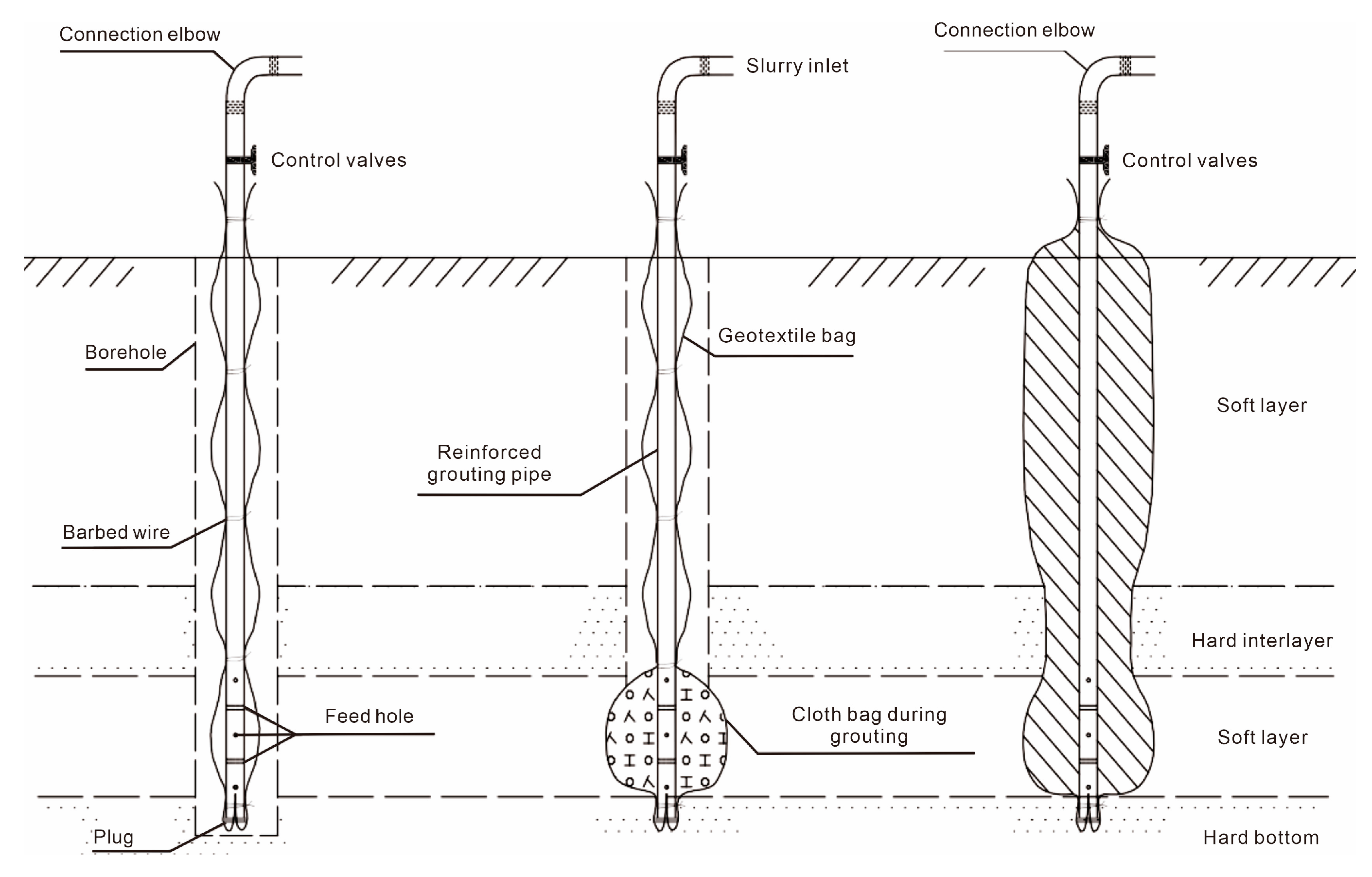
A bag grouting pile is an effective method for strengthening a deep soft soil foundation. It involves the pre-embedding of geotextile bags into the soft soil foundation and then injecting grout from the bottom of the pre-drilled hole. This process causes the hole wall to expand from the bottom, forming regular cylindrical or gourd-shaped stones. These stones interact with the surrounding soil to form a composite foundation, achieving the goal of strengthening the soft soil foundation (
Figure 4). Therefore, the bag grouting pile essentially relies on the compression and expansion of the pre-drilled hole wall to disturb the soil. Bag grouting piles are appropriate for fortifying deep soft soil foundations due to their stable pile performance, convenient construction, and high shear resistance. It has evident benefits for site-restricted or soft-soil foundations with solid interlayers.
(2) Assumptions
Based on the mechanism of bag grouting pile formation and the theory of column (or sphere) expansion, a model is established to simulate the disturbance effect of bag grouting pile formation on the soil by gradually expanding the borehole wall from bottom to top at predetermined pile positions. This simulation method is based on the following assumptions:
a. The process of bag grouting pile formation is quasi-static during soil squeeze.
b. The variation of pile diameter within the vertical range of the pile body is ignored.
c. The variation of pile diameter caused by internal pressure adjustment following grouting expansion is ignored.
(3) Simulative steps
The main steps of the simulation process are as follows:
i. Establishment of bag grouting pile reservation grids: this component consists of a cylindrical pile body and a hemispherical pile tip with a radius equal to one-fourth of the actual pile diameter.
ii. Establishment of soil grids around the pile: the vertical and lateral lengths of the model are both twice the length of the pile, and the grids are slightly dense near the pile.
iii. Calculation of initial soil state: define all grids as soil, assign material parameters, set gravity load, and complete the calculation of initial stress as well as initial modulus.
iv. Gradual grouting and expanding from bottom to top: first, close the grid at the pile location and then apply horizontal displacement to the hole wall at the grouting location. The grouting process should start with an initial radius and gradually expand from bottom to top to achieve the actual pile diameter.
3.3. Bored Pile
(1) Mechanism
The construction process of a bored pile includes several stages, such as drilling, placing a reinforcement cage, and pouring concrete (see
Figure 5). Unlike the two previously mentioned pile types that cause soil squeezing, the bored pile generates significant disturbance to the surrounding soil during the drilling stage, which is caused by the soil unloading effect. Therefore, to investigate the soil disturbance effect caused by the bored pile, a simulation of the drilling process is conducted.
(2) Assumptions
The simulation process is based on the theoretical foundation of circular hole contraction. Under natural stress conditions, the soil elements inside the hole are gradually closed from the top to the bottom. Simultaneously, static water gradient pressure is applied to the hole wall to simulate the support of mud on the hole wall. This approach enables the simulation of the contraction behavior of the drilling hole under the combined effect of natural stress and mud pressure. The simulation method is based on the following assumptions:
a. Ignoring the infiltration of slurry moisture.
b. Ignoring the vibration effects generated by the drilling machine.
(3) Simulative steps
The main steps of the simulation process are as follows:
i. Establishment of bored pile grids consisting of cylindrical pile components with the same diameter as the pile itself.
ii. Establishment of soil grids around the pile: the vertical and lateral lengths of the model are both twice the length of the pile, and the grids are slightly dense near the pile.
iii. Calculation of initial state of soil: define all grids as soil, assign material parameters, set gravity load, and complete the calculation of initial stress and initial modulus.
iv. Drilling from top to bottom: close the grid at the pile location, apply normal pressure to the hole wall at the drilling location with the pressure being distributed in a hydrostatic gradient in the vertical direction, gradually close the grid from top to bottom, and apply pressure.
Further, to quantify the deformation of the soil around the pile during the pile driving process, this study selects four characteristic values at distances of 10R, 20R, 30R, and 50R from the center of the pile, based on the calculation results.
4. Results
4.1. Disturbance Effects of Hydrostatic Pile
(1) Dynamic response characteristics of soil displacement fields during the pile driving process
Figure 6 shows the distribution of horizontal displacement of soil in the depth direction when the horizontal distance from the pile center is 10R. The penetrating procedure is divided into ten steps, with result files saved after each step. As the pile penetrates, the horizontal displacement increases with steps, during which the curves exhibit an L-shape at first and then change to S-shape. The distribution of horizontal displacements in the depth direction of soil is shown in
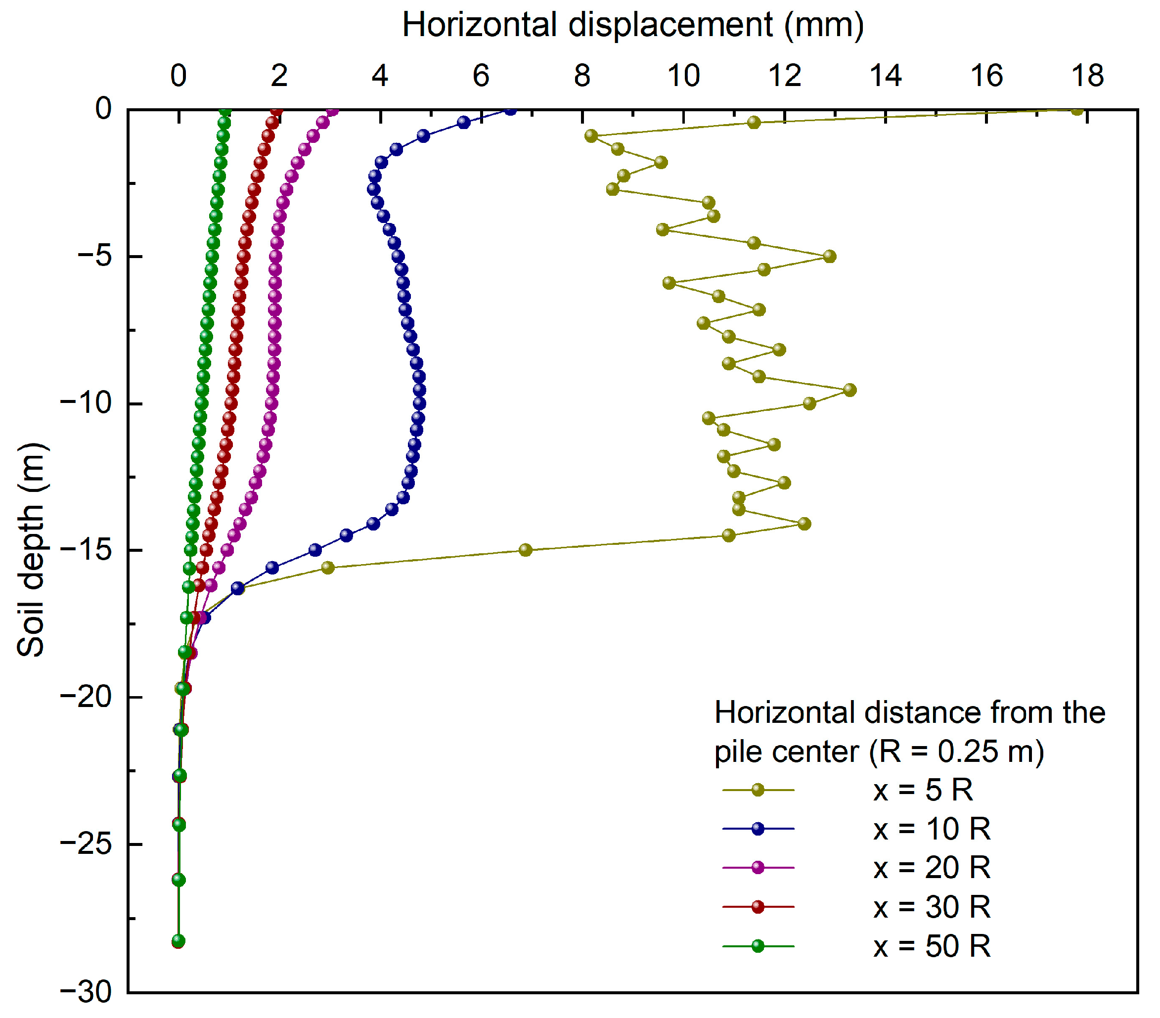
Figure 7. From close to far, the horizontal displacement caused by the penetration of the hydrostatic pile gradually decreases. In the depth direction, the displacement curve displays an S-shaped distribution pattern, namely, large in the shallow part, average in the middle, and small in the lower part. As the horizontal distance from the pile center increases, the S-shaped curve progressively flattens.
As for the vertical displacement field,
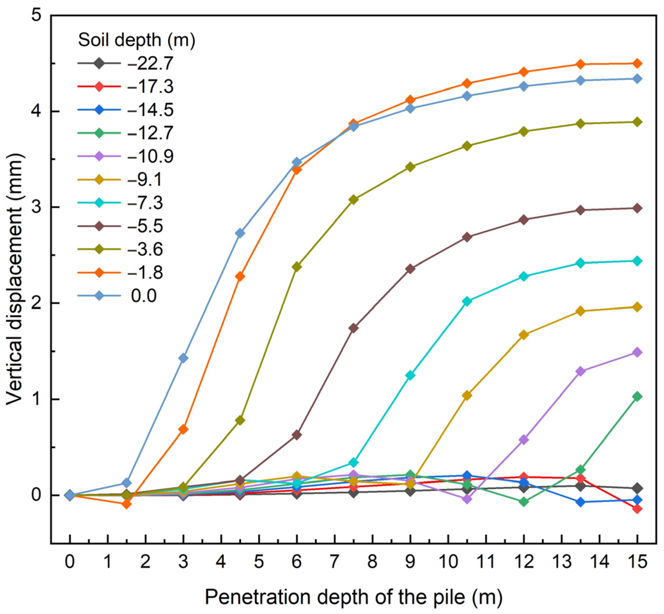
Figure 8 depicts the distribution of vertical displacement with depth at 10R from the pile center, where the disturbance at the surface is the greatest, and the vertical displacement increases progressively with increasing penetration depth and tends to be constant. When the pile tip reaches a particular depth, the vertical deformation of the soil at that depth begins to increase substantially and then tends to be flat.
Figure 9 shows the distribution of vertical displacement in the horizontal direction at different depths, where the vertical displacement is concentrated within a horizontal distance of 5 m from the pile center and decreases substantially with increasing distance, roughly following a logarithmic curve.
(2) Dynamic response characteristics of soil stress field during the pile driving process
Figure 10 presents the variation of horizontal stress at a depth of half the pile length with the penetration. The horizontal stress varies slightly at each horizontal distance as the hydrostatic pile penetrates from the surface z = 0 to the depth z = 6 m. After z = 6 m, the soil stress increases as the horizontal distance from the pile center decreases. The stress diminishes and is maintained at a stress level that is greater than the natural stress.
Figure 11 depicts the distribution of horizontal and vertical stresses of the soil at different depths along the horizontal direction after the completion of pile penetration. The curves of the horizontal and vertical stresses show similar trends. Near the pile, both the horizontal and vertical stresses have a significant increase. As the distance from the pile increases, the disturbance effect of the pile on the soil gradually weakens, and the stress drops and remains steady at a certain level. In general, the disturbance of the horizontal stress is more significant than that of the vertical stress.
(3) Range of pile disturbance
Figure 12 shows the variations in the elastic-plastic region of the pile during the driving process. It can be observed that the pile tip is always in the plastic development zone, and the surface soil undergoes continuous plastic deformation during the driving process. By comparing
Figure 12e,f, it can be found that when the penetration depth exceeds half of the pile length, the elastic-plastic region of the surface soil is no longer affected.
To visually illustrate the spatial distribution and disturbance range characteristics of soil disturbance, 0.1 kPa, and 1.0 mm are selected as characteristic values of the additional stress and deformation of the soil, respectively. If these values are underneath predetermined thresholds, the soil is considered undisturbed.
Figure 13a,b illustrate the contour map of additional stress in the final state. The horizontal additional stress has a range of disturbance of 3.8 m and 13.0 m in the horizontal and vertical directions, respectively. In contrast, additional vertical stress has a smaller range of disturbance, with ranges of 1.9 m and 12.1 m in the horizontal and vertical directions, respectively. In addition,
Figure 13c,d demonstrate the contour map of displacement in the final state. The horizontal displacement has a range of disturbance of 7.6 m in the horizontal direction and reaches its maximum disturbance on the ground in the vertical direction. Meanwhile, the vertical displacement has a smaller range of disturbance, with ranges of 4.3 m and 3.8 m in the horizontal and vertical directions, respectively.
4.2. Disturbance Effects of Bag Grouting Pile
(1) Dynamic response characteristics of the soil displacement field during the pile grouting process
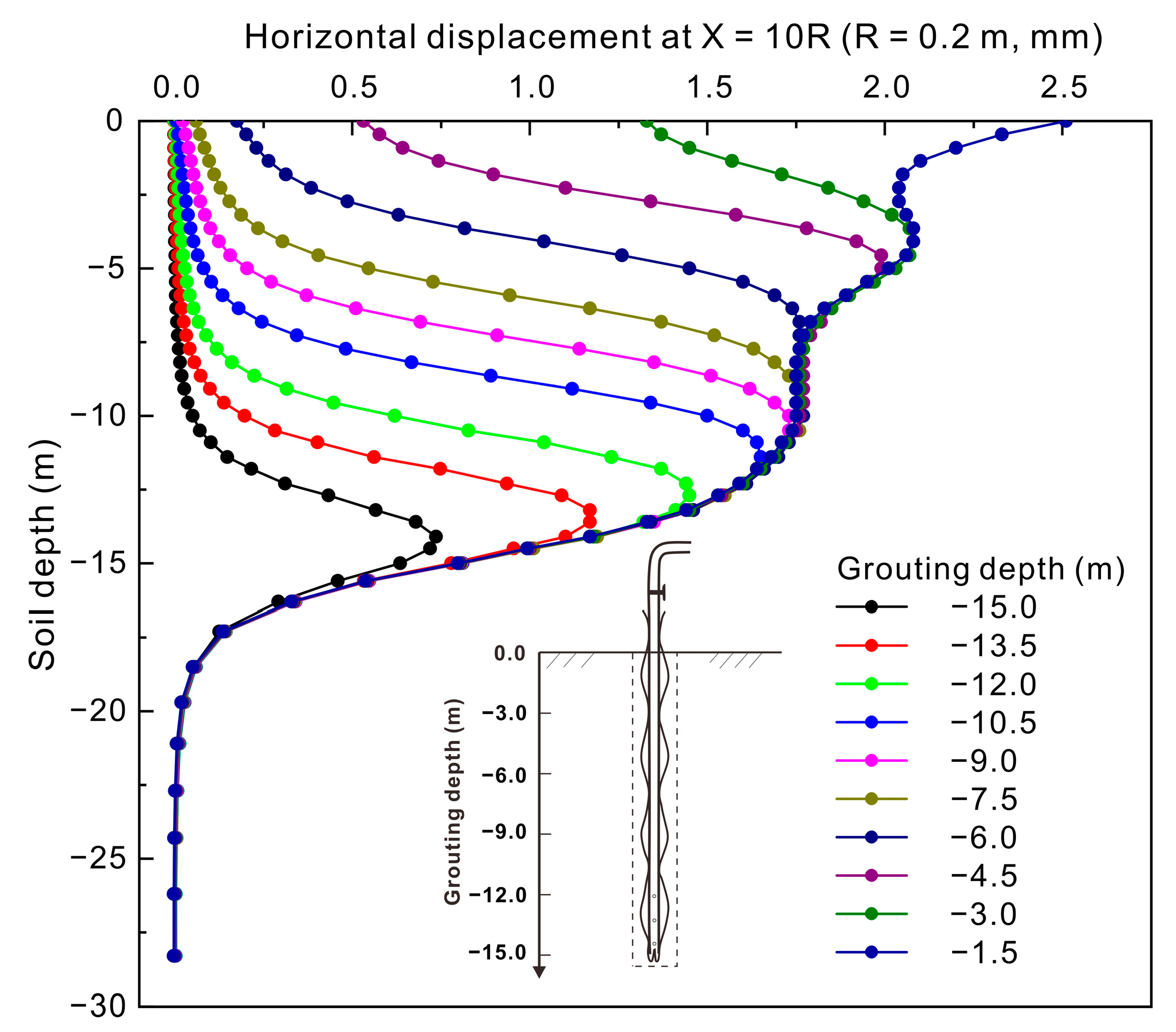
Figure 14 shows the distribution of the soil horizontal displacement in the depth direction when the horizontal distance from the pile center is 10R. When the grouting level rises, the lateral squeeze will occur, causing horizontal displacement of the soil.
Figure 15 displays the distribution of horizontal displacements at various horizontal distances in the depth direction. It can be observed that the horizontal displacements induced by the bag grouting pile decrease progressively from near to far, ultimately conforming to a linear distribution law of “large above and small below”.
Figure 16 shows the distribution characteristics of vertical displacement in the soil at various depths in the horizontal direction. It reveals that the maximum vertical deformation of the soil occurs near the pile position and decreases gradually with increasing distance from the pile center, roughly following a logarithmic curve. Additionally,
Figure 17 demonstrates that when the pile tip reaches a particular depth during the pile grouting process from deep to shallow, the vertical deformation of the soil at that depth begins to increase substantially and then flattens out.
(2) Dynamic response characteristics of the soil stress field during the pile grouting process
Figure 18 shows the variation of horizontal stress of the soil at different horizontal distances from the center of the pile at a depth of half the pile length. As the grouting level increases, the horizontal stress of the soil increases, and the closer the distance to the pile in the horizontal direction, the more significant the increase in stress.
Figure 19 depicts the distribution of horizontal and vertical stresses of the soil at different depths along the horizontal direction after the completion of pile penetration. Near the pile, both the horizontal and vertical stresses have a significant increase. As the distance from the pile increases, the disturbance effect of the pile on the soil gradually weakens, and the stress drops and is maintained at a certain level. It also shows the disturbance of the horizontal stress is more significant than that of the vertical stress.
(3) Range of pile disturbance
Figure 20 shows the variations in the elastic-plastic region of the pile during the grouting process. It can be observed that the pile tip is always in the plastic development zone, while there is no plastic deformation in the surface soil during deep grouting. As the grouting level increases, the bottom hole wall continues to make plastic deformation.
Similarly, characteristic values of 0.1 kPa and 1.0 mm were chosen to represent the additional stress and deformation of the soil, respectively. The contour map in
Figure 21a,b show the distribution of additional stress in the final state, with a disturbance range of 2.2 m and 13.0 m in the horizontal and vertical directions for the additional horizontal stress, and 1.0 m and 12.0 m in the horizontal and vertical directions for the additional vertical stress.
Furthermore,
Figure 21c,d display the final displacement contour map. The horizontal displacement has a disturbance range of 3.0 m in the horizontal direction; the maximum disturbance range in the vertical direction is on the ground. On the other hand, the vertical displacement has a disturbance range of 1.4 m in the horizontal direction, while the maximum disturbance range in the vertical direction is also on the ground.
4.3. Disturbance Effects of Bored Pile
(1) Dynamic response characteristics of the soil displacement field during the hole formation process
Figure 22 illustrates the distribution of horizontal soil displacement in the depth direction at a horizontal distance of 10R from the center of the pile. It is observed that during the drilling process, the soil experiences a progressive increase in horizontal displacement toward the borehole with the advancement of penetration depth. Notably, the ground disturbance is maximal during this process. Furthermore,
Figure 23 presents the distribution of horizontal soil displacement in the depth direction at varying horizontal distances. The disturbance in the horizontal displacement field of the soil increases with the proximity to the pile. In the depth direction, the displacement curve exhibits an S-shape distribution away from the borehole.
As for the vertical displacement distribution pattern,
Figure 24 presents the distribution features of the vertical soil displacement in the horizontal direction at varying depths. It is found that the soil near the pile undergoes minor settlement in the vertical direction, which diminishes significantly as the distance increases. Furthermore, the shallow soil near the borehole undergoes minor relative uplift, while the deep soil experiences two prominent settlement distribution variations, one near the borehole and the other at a horizontal distance of approximately 12 m from it.
(2) Dynamic response characteristics of the soil stress field during the hole formation process.
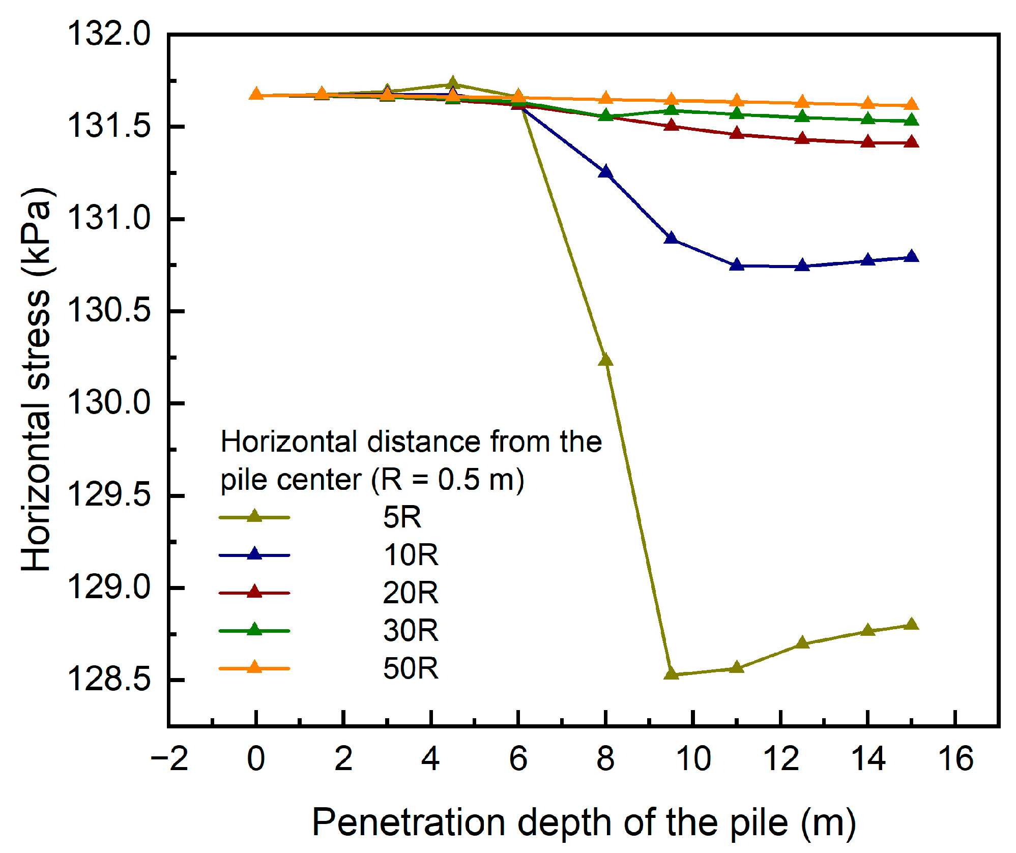
Figure 25 depicts the variation of horizontal stress in the soil at different horizontal distances from the pile center at half the pile length depth. At drilling depths ranging from 0 to 6 m, no significant changes in horizontal stress were observed at different horizontal distances from the pile center. However, as the drilling depth exceeded 6 m, a decrease in soil stress was evident, and the stress reduction was greater with decreasing distance between the soil and the pile.
In
Figure 26, the distribution characteristics of horizontal and vertical stresses in the soil after drilling are presented in the horizontal direction. Both stresses exhibit a consistent trend of increasing with the soil depth. Additionally, there is a slight variation in stress near the drill hole, and it is relatively small compared with the first two types of piles. This indicates that the bored pile induces less soil disturbance compared with the other two types of piles.
(3) Range of pile disturbance
Figure 27 illustrates the variation of the elastic-plastic region of the pile during the drilling process, where the pile tip remains in the plastic development zone. When the drilling reaches one-third of the pile body, the superficial soil no longer undergoes plastic deformation.
In addition, this section employs 0.1 kPa and 1.0 mm to represent the additional stress and deformation characteristic values of the soil, respectively.
Figure 28a presents the contour map of the horizontal additional stress of the soil when the drilling reaches the final state where the disturbance range of additional horizontal and vertical stress is 3.5 m and 13.5 m, respectively. The horizontal direction of the additional vertical stress has almost no effect (not discussed in this model).
Figure 28b shows the contour map of displacement in the final state. The disturbance range of the soil in the horizontal direction is only 1.1 m for a deformation characteristic value of 1.0 mm, while the vertical perturbation depth is at 7.0 m. The horizontal disturbance range of the vertical displacement is also negligible in this model.
5. Discussion
Three important indicators—namely, horizontal displacement, vertical displacement, and horizontal stress—were selected to compare and analyze the disturbance effects on the soil of three types of piles: hydrostatic piles, bag grouting piles, and bored piles (
Figure 29). Regarding horizontal displacement, it is evident that hydrostatic piles cause the greatest disturbance during the pile driving process, followed by bag grouting piles and bored piles. The horizontal expansion of the pile during the pile driving process may be the controlling factor that affects the magnitude of disturbance effects, with hydrostatic pile requiring a nearly zero aperture to be expanded to 500 mm during the piling process, bag grouting pile usually expanding the aperture from 300 mm to 400 mm, and the bored pile not expanding the aperture. In addition, the disturbance of soil horizontal displacement caused by the three types of piles is inversely proportional to the distance between the soil and the pile center. The same conclusion applies to vertical displacement. It is worth noting that the horizontal disturbance of the three types of piles on the soil during the pile driving process is greater than the vertical disturbance. Therefore, a further study on the disturbance characteristics of the horizontal stress field was conducted, and a general rule was obtained that soil stress increases as the horizontal distance from the pile center decreases. Furthermore, the stress changes produced by hydrostatic piles during the pile driving process are the greatest, followed by bag grouting piles and bored piles. These findings provide an important reference for selecting pile foundations.
According to the previously mentioned research, the penetration of piles causes the most disturbance to the soil in the horizontal direction. Therefore, under the same soft soil parameters and pile length conditions, 0.1 kPa and 1.0mm were chosen as the characteristic values of horizontal stress and horizontal displacement, respectively, to visually represent the horizontal disturbance range of the three types of piles on the soil. By standardizing and comparing them, more precise conclusions were reached. Using 0.1kPa as the characteristic value of horizontal stress, the horizontal disturbance ranges of the three are, in order, 3.8 m, 2.2 m, and 3.5 m. The normalized values are 7.6, 5.5, and 3.5, respectively, when divided by the pile diameter. The maximal disturbance range is roughly 1/5 of the pile length above the pile tip. Using 1.0mm as the characteristic value of horizontal displacement, the horizontal disturbance ranges of the three are 7.6 m, 3.0 m, and 1.1 m, respectively. The normalized values are 15.2, 7.5, and 1.1 when divided by the pile diameter, respectively. The horizontal disturbance range is at its greatest near the surface. Consequently, the hydrostatic pile disturbs the soil the most, followed by the bag grouting pile and the bored pile.
It is worth noting that this comparison study by numerical simulation has made some simplifications. For example, for bag grouting piles, the nonlinear process of slurry pressure distribution throughout the hole is not considered, and neither is the expansion degree and sequence of different formation stiffness, which may have affected the calculated results. For the bored piles, it is difficult to use them in soft soil without a steel shield; also, the damage to soft soil structure caused by unloading is not considered. These should be further considered in practical construction.
In order to select the best piling method, it is important to consider both the disturbance effect and engineering practice. Based on practical experience, hydrostatic piles have advantages such as low unit-bearing capacity cost, guaranteed quality, short construction time, adjustable pile positions, and low slurry production. However, their construction requires strict bearing capacity requirements for the site. On the other hand, bag grouting piles offer advantages such as controllable body quality, compaction degree, and feasibility for various geological conditions. Nevertheless, their prolonged construction period limits their practical use. Bored piles offer high bearing capacity, large diameter construction capability, and versatility for various foundations, but they have drawbacks such as slow drilling speeds and the potential for slurry contamination. Thus, in engineering applications, the optimal piling method can be selected by considering factors such as construction difficulty, economic costs, and the allowable range of disturbance. Further, although this study enables a synthetic comparison among three piling patterns on their disturbance to the soft soil foundation, the same conclusion (optimal order) may not be applicable when driving piles into other strata.
6. Conclusions
A comprehensive comparison of the disturbance effects of pile driving on soft soil foundations for both squeezed and non-squeezed soil piles was presented. Based on the analyses of the pile disturbance mechanism and hypothesis, as well as the indoor test results, the numerical simulation of the single pile driving processes for the hydrostatic pile, bag grouting pile, and bored pile were carried out by using FLAC3D. Specifically, a novel construction method for numerical models was proposed and employed to simulate the mechanical processes of different pile types under standard grids. The evolution characteristics of the soil displacement field, stress field, and disturbance range under single-pile disturbance for the three types of piles were compared and studied, thus revealing the disturbance effects of different types of piles on the soil. Specific conclusions are drawn:
(1) An analysis of the disturbance mechanisms associated with squeezed and non-squeezed soil piles indicates that their respective disturbance effects on the soil are the squeezing effect and unloading effect. Based on this, a numerical simulation study on the soil disturbance caused by pile installation is conducted.
(2) Simulative findings demonstrate that there are notable differences in the effects of three types of piles on soil disturbance. The two types of squeezed soil piles have caused significant disturbances to the soil displacement field, particularly in the horizontal direction. However, the impact on the soil stress field is relatively small. Among them, the hydrostatic pile has a larger disturbance magnitude and range than the bag grouting pile. For non-squeezed soil piles, the bored pile causes the smallest variation in the soil displacement field during the pile driving process. Moreover, the stress field of the soil remains mostly unchanged.
(3) The comparison of the disturbance effects of the three types of piles on the soft soil foundations has been carried out by quantifying the disturbance range of the stress field and displacement field of soil. The results reveal that the disturbance range of horizontal stress and deformation is greater than that of vertical stress. Normalization has been performed on the horizontal stress and deformation disturbance ranges of hydrostatic piles, bag grouting piles, and bored piles. The horizontal disturbance values of maximum horizontal stress for all three types of piles are approximately 1/5 of the pile length above the pile tip, with normalized values of 7.6, 5.5, and 3.5, respectively. As for the maximum horizontal deformation disturbance range in the horizontal direction, it occurs near the ground surface, and the normalized values are 15.2, 7.5, and 1.1, respectively. Consequently, the disturbance effect of the hydrostatic pile on soil is found to be the greatest, followed by the bag grouting pile and the bored pile.


