Communication

A Low-Profile Dual-Polarized Magneto-Electric Dipole Antenna for 5G Applications

School of Electronics and Information, Hangzhou Dianzi University, Hangzhou 310018, China
*
Author to whom correspondence should be addressed.
Appl. Sci. 2023, 13(1), 530; https://doi.org/10.3390/app13010530
Submission received: 7 December 2022 / Revised: 17 December 2022 / Accepted: 22 December 2022 / Published: 30 December 2022

Abstract

:
A low-profile dual-polarized magneto-electric dipole (MED) is presented in this communication. The low profile was achieved using meander slots on the vertical magneto dipole, reducing the antenna height to 0.15λ0, where λ0 is the wavelength of the center frequency. Relatively, the proposed MED structure is easier to process and more stable than the traditional low-profile MED structure. The broadband performance for 5G Applications was realized based on MED structure, and the dual-polarization structure has wider coverage area and lower multipath transmission losses. Moreover, the orthogonal feeding structure provides a satisfying isolation between two ports. To verify the simulation results, a prototype of the proposed antenna was fabricated and measured. The results show that the overlapped operating frequency bandwidth with |S11| ≤ −10 dB, |S12| ≤ −20 dB was 36.8% from 3.1 GHz to 4.5 GHz, the peak gain reached 10.2 dBi, and the average gain exceeded 8.5 dBi. The measured 3 dB beamwidth with more than 44 degrees beamwidth was realized in both E-plane and H-plane. In addition, cross-polarization levels below −22 dB that covered the above frequency band were achieved. Compared with other MED antennas, in addition to broadband and high gain, the proposed antenna has the advantages of a low profile, easy processing, and low cost, which make it a competitive candidate for 5G applications.

1. Introduction

With the rapid development of 5G systems, a high-performance antenna is necessary as one of the basic structures of such communication systems. For example, broadband designs were applied in [1,2] to improve system capacity and reduce cost. Low cross polarization and low back radiation [3,4] were designed to reduce external interference. Stable radiation pattern and gain in working frequency band [5,6] were used to improve signal quality, and the miniaturization and easy integration design [7,8] are considered to reduce system costs and save space. The spectrum for 5G communications can be divided into Sub-6 GHz and millimeter wave bands; compared with millimeter wave bands, the Sub-6 GHz band has more advantages in signal attenuation, penetration, coverage, and so on. This also means that to achieve the same wide 5G signal coverage, sub-6 GHz 5G base station deployment density must be lower; the required base station cost can also be made lower [9,10].
In 2006, Kwai-Man Luk proposed a MED antenna based on the complementary principle [11]. In the MED, the magnetic dipole is a U-shaped structure composed of a metal floor and vertical metal walls, and the electric dipole consists of horizontal metal patches. Both of two dipoles are excited in two vertical directions, thus the performance of a stable and symmetrical pattern, low back lobe radiation, and low cross polarization can be realized, making it an optimal choice for many wireless communication systems. However, the disadvantages of the MED, such as its three-dimensional (3D) structure, high profile, and large volume are also obvious. Therefore, with the aim of solving these disadvantages, it is necessary to carry out corresponding miniaturization research, with the emphasis on reducing the profile height of the MED.
The profile height of the MED antenna is determined by the U-shaped structure composed of the vertical metal wall and the floor, which is equivalent to the magnetic dipole antenna. Therefore, if the height of the U-shaped structure was reduced, a low-profile MED will be realized. A method of folding vertical metal wall [12,13] and another method of inclining metal wall [14,15] are used to partially realize a low profile, but the correspondingly structural stability is inferior and the 3D structure of the antenna is more complicated. A number of researchers put emphasis on loading dielectric to achieve a low profile [8,16,17,18]; compared with no dielectric, the waveguide wavelength of the MED antenna can be reduced by adding dielectric between vertical metal walls, which means a lower profile in physical dimension. However, because of the added dielectric, the processing cost and difficulty also increase.
In this study, a low-profile MED antenna was provided by meandering slots on the magnetic dipole antenna. Since the meandering slots were set on the plane structure, this meant that the low-profile structure was more convenient to process. In addition, a dual polarization structure was adopted to achieve a more desirable antenna performance. Compared with the other proposed broadband MED antennas adopting meandering slot, the vertical metal wall was designed to be a lower cost alternative. In Section 2, the structure, the operating principles, and simulated results of the proposed MED antenna are presented. Section 3 introduces the measured results of the fabricated MED. Finally, Section 4 draws a concise conclusion.

2. Materials and Methods

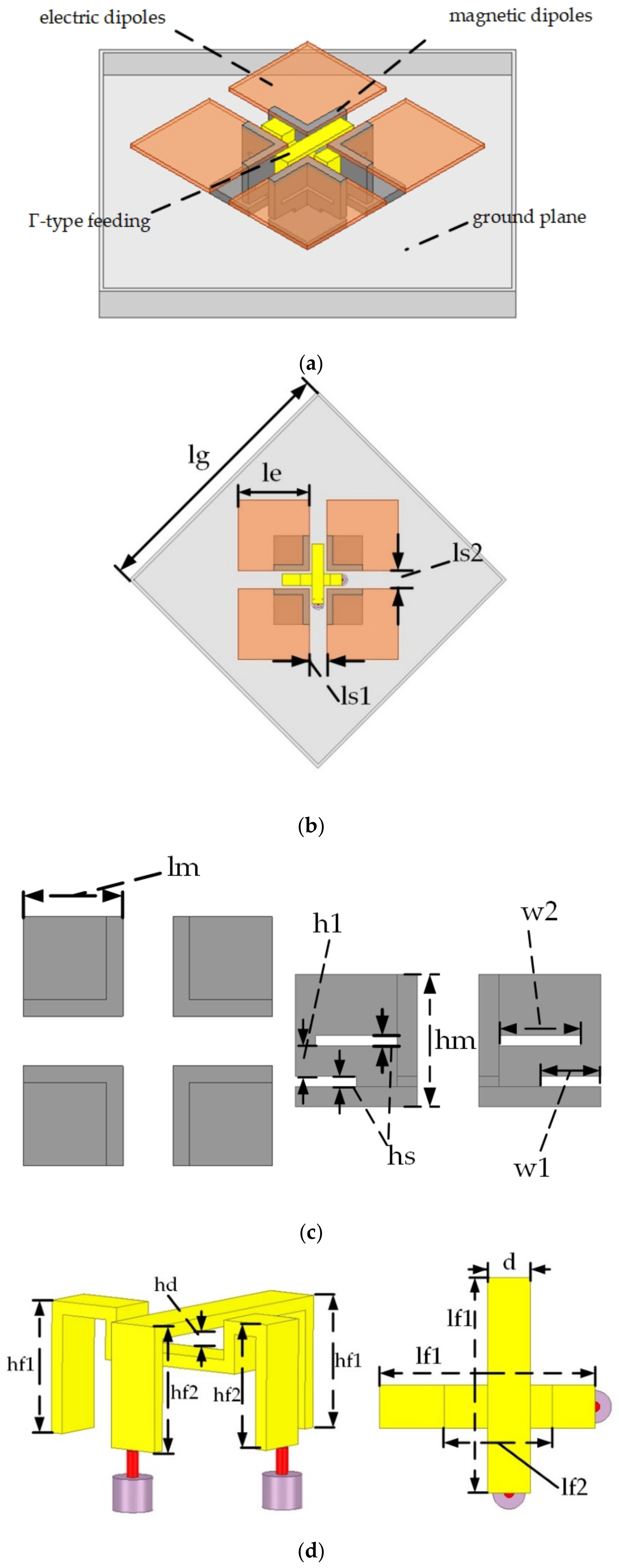
2.1. Antenna Structure

The 3D structure of the low profile broadband dual polarization MED antenna is shown in Figure 1a, which consisted of four parts: (1) horizontal electric dipoles composed of four-square metal patches; (2) magnetic dipoles consisting of four vertical metal structures; (3) two crossed Γ-type feeding structures located in the middle of the antenna; (4) a metal floor with reflective structure. Moreover, the bottoms of the Γ-type feeding structures were connected to the SMA connectors under the ground, and the rectangular slots were etched on the vertical metal wall to reduce the antenna profile. The specific structure is shown in Figure 1b–d.
The center frequency of the proposed antenna was set at 3.8 GHz, and then the antenna was designed and optimized to realize a high gain and a broadband working bandwidth with the commercial software ANSYS High Frequency Structure Simulator (HFSS). The final optimized parameters in Figure 1 are presented in Table 1, and the optimized procedure is provided in Section 2.4. Furthermore, the metal thickness of the electric dipoles, feeding structures, and metal floor were 1mm, and that of the magnetic dipole was 2 mm.

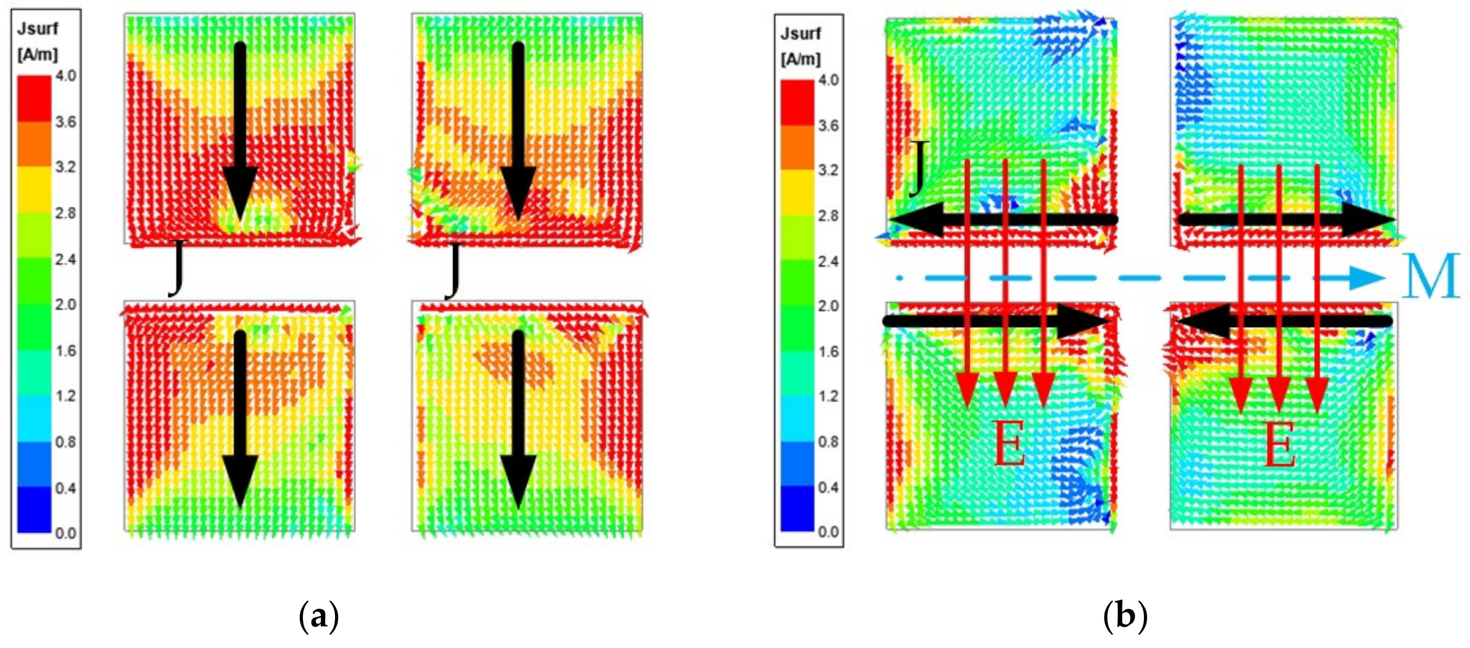
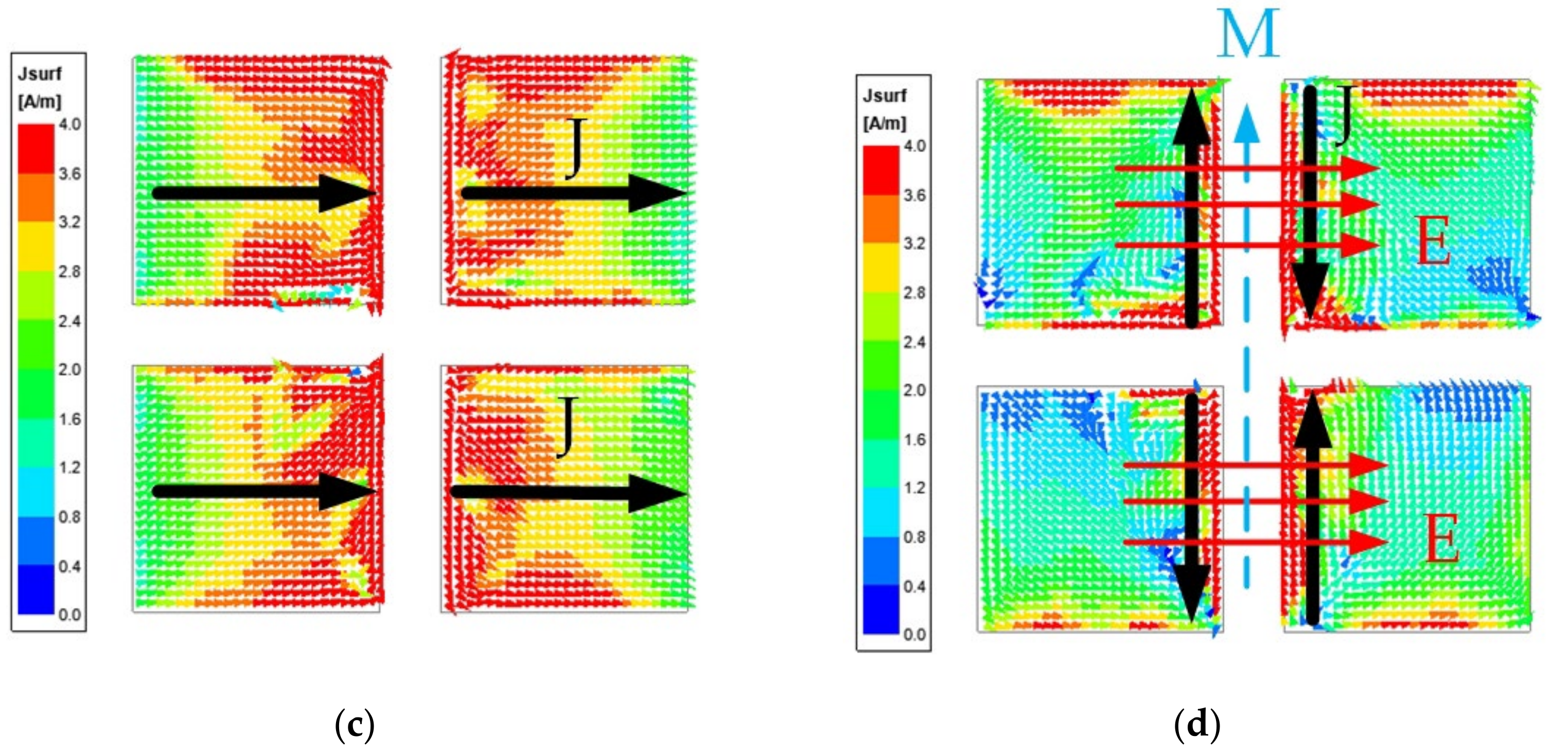
2.2. Dual-Polarized Structure

Compared with single-polarized antennas, dual-polarized antennas can realize duplex transmission and reception, and also expand communication capacity, which means greater advantages in the field of communication. At the same time, the dual-polarized antenna has stronger anti-interference ability, which can effectively resist multipath fading and improve the sensitivity of the system. In the design of dual-polarized antennas, the design of the feed structure counts a great deal.
Some researchers use slot coupling feeds in antenna design [19,20], in order to realize higher isolation between different ports. However, it also results in a higher processing cost and structural complexity. Γ-type feeding structures with simple structures and low processing costs can realize impedance matching in a wide frequency band; hence, Γ-type feeding structures were adopted in the proposed antenna. Figure 1d shows the Γ-type feeding structures consisting of three parts. The first part is the vertical part whose bottom is connected with the coaxial core under the metal ground. The second part, i.e., the horizontal part of the Γ-shaped feeding structures, which is inductive, transmits energy to the horizontal electric dipole and the vertical magnetic dipole by coupling. The vertical part on the other side is the third part of the Γ-shaped feeding structures, which is capacitive. By optimizing the length of the third part, the capacitive part and the inductive part of the second part can cancel each other out. The horizontal part of one feeding structure was bent to improve the isolation of two ports.
Figure 2 depicts the current distributions on the electric dipoles when the two ports are excited separately, and T is one operational period. The current on the electric dipoles reached the maximum intensity at time 0; see Figure 2a,c, which indicate that the horizontal metal patches were strongly excited. Meanwhile, at time T/4, the currents on the horizontal metal patches attained minimum intensity, but the currents on the radiating slot between the patches reached the maximum, as shown in Figure 2b,d. This means that the magnetic dipole was strongly excited. In summary, the electric dipole and the magnetic dipole were alternately excited, in line with the operating characteristics of the MED. The above results show that the two ports excited similar intensity on the MED. Therefore, the feeding structures could be used to excite the dual-polarized MED.

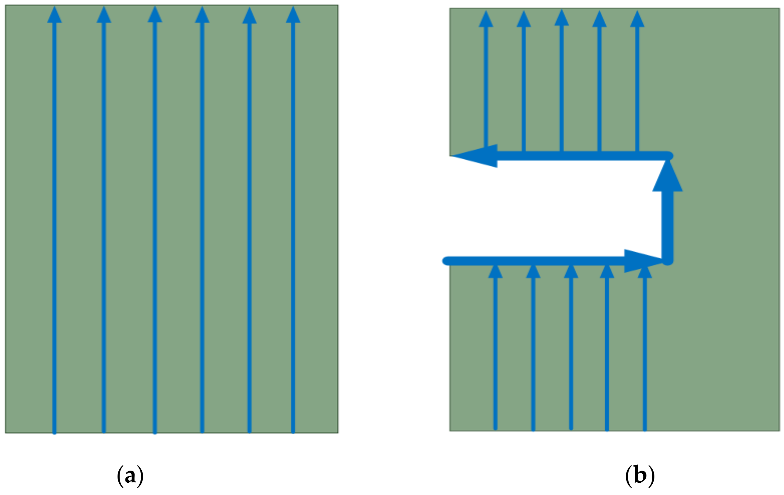
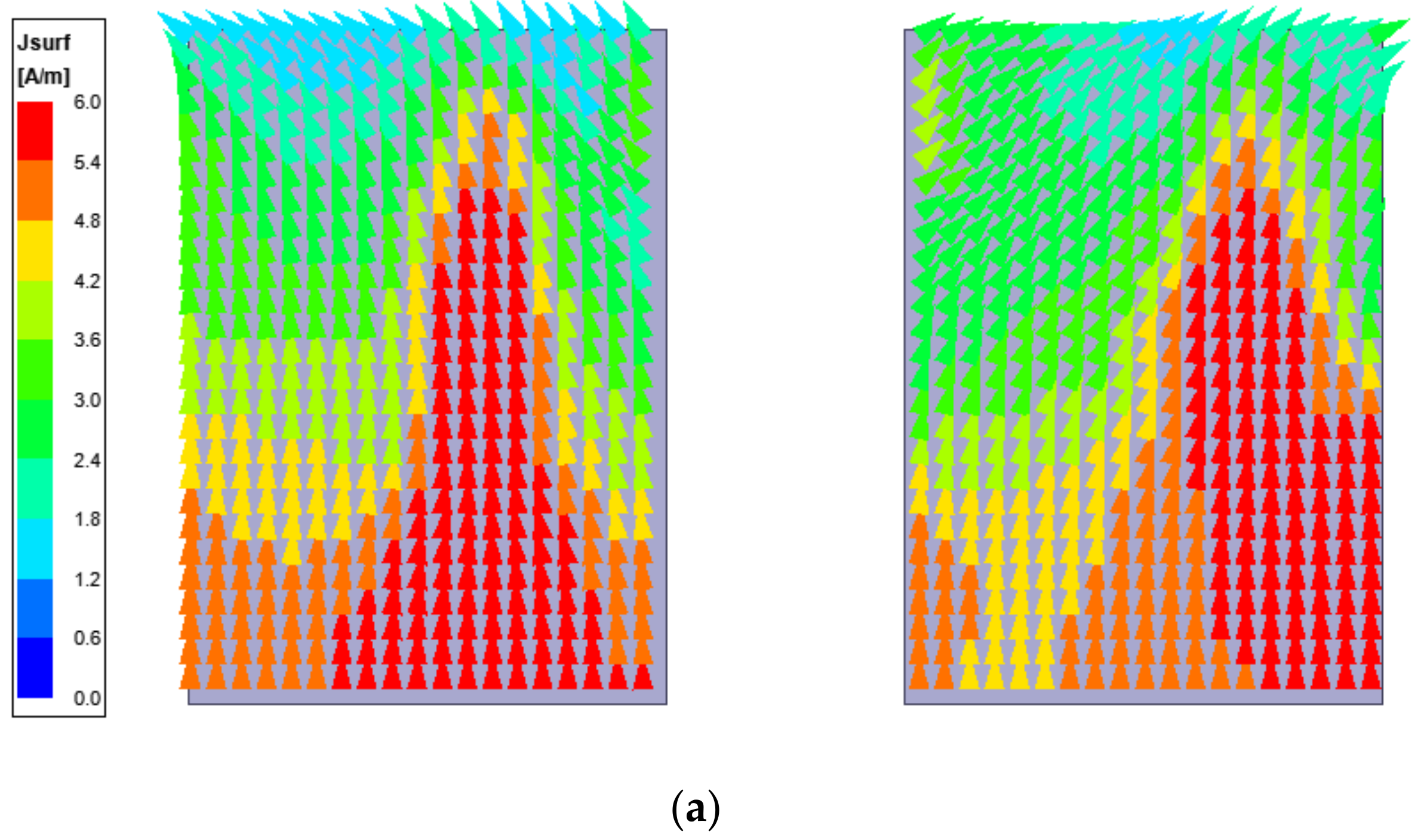
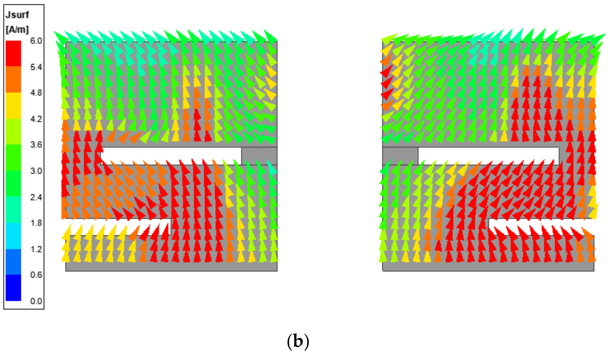
2.3. Magnetic Dipole Structure

In the design of many MEDs, magnetic dipoles and electric dipoles are integrated, which leads to complicated or unstable structures of MEDs. In the proposed antenna, the magnetic dipoles, that is, the vertical metal walls, were separately processed into a stable structure, as shown in Figure 1c. The magnetic dipoles were designed as four three-sided structure units, in addition to the vertical metal wall of each unit as a magnetic dipole; another metal wall was added at the bottom to make the structure of the magnetic dipole more stable.
According to the principles of antenna theory, the antenna usually resonates at about half a wavelength, which is applicable to electric dipole antennas and magnetic dipole antennas. It can be inferred that the magnetic dipole antenna can resonate at the original frequency, as long as the total current path is similar to that of the prototypical antenna, thus realizing the design of a low-profile antenna. The methods of reducing the MED profile were described in Section 1. Here, the meandering slots method adopted by the proposed antenna is introduced in detail.
Figure 3 exhibits the theoretical current distributions on the magnetic dipole, i.e., the vertical metal wall. The total length of the magnetic dipole was close to half a wavelength; that is, the total length of the current path on the magnetic dipole was close to half wavelength. Slots were added to the magnetic dipole, as slots prevent the conductive current from passing through; the conductive current bypasses the slots and continues to flow after encountering the metal slots, as shown in Figure 3b. The path length of the current increases, which is equivalent to prolonging the length of the magnetic dipole, and the purpose of meandering can be achieved by etching the slots. That is, the slots can reduce the profile of the antenna when the center frequency is constant. Next, it is necessary to explain how and where the slots were etched.
First of all, the current distribution must be analyzed when selecting the slot position, and the best meandering effect can be obtained when the slot is opened at the position with the maximum current. As shown in Figure 4a, the maximum current distribution of the slotless magnetic dipole tended to be distributed closer to the vertical part of the feeding structure. Therefore, the location of the slots was preferentially chosen according to the specific current distribution in the actual design. Taking the proposed low-profile MED obtained after etching slots as an example, the current distribution on the vertical wall is shown in Figure 4b. It can be seen that when the currents flowed from bottom to top after the slots were etched, the currents of the vertical wall flowed along the meandering slots, thus realizing meandering. The purpose of extending the current path with the meandering current was eventually achieved.

2.4. Parametric Analysis
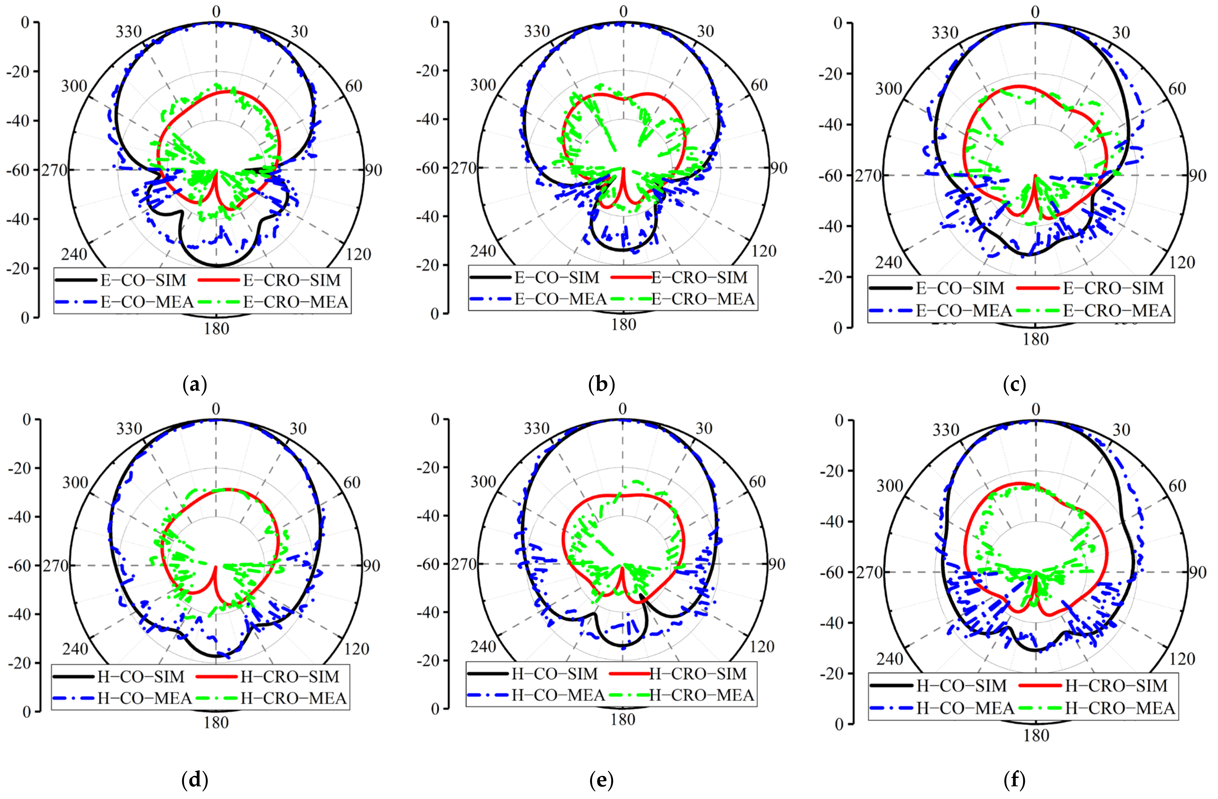
The working principle and structural advantages of the proposed MED were introduced above. The electric dipole structure adopted the common square patch structure, and the metal floor structure adopted the fence structure, which is described in detail here. This part focuses on the influence of parameter dimensions on the proposed MED performance. Antenna models with different parameter dimensions were modeled and simulated by HFSS; then, the influence of parameter dimensions on the proposed MED performance was analyzed, and finally the optimal parameter dimensions were compared and selected from the simulation results.
The simulation results of different parameter dimensions are shown in Figure 5. As we can see, the length of the electric dipole affected the second resonance at around 4.3 GHz, with an increase in the length, the resonance and the peak gain moved to a lower frequency, the reflection coefficients became better, but the working bandwidth became narrower. In order to balance the performance of the MED, a suitable length le = 24 mm was chosen.
Figure 5b shows that the height of the magnetic dipole affected the first resonance at around 3.5 GHz. With an increase in the height, the resonance moved to a lower frequency, the working bandwidth became wider, but the reflection coefficients became worse. In order to balance the performance of the MED, a suitable length hm = 13 mm was chosen. The influence of the length of the magnetic dipole is shown in Figure 5c. As we can see, as the length of the magnetic dipole increased, both of the two resonances and gain peaks moved to lower frequencies. Therefore, the appropriate magnetic dipole length should be selected according to the set center frequency, i.e., 3.8 GHz.
Figure 5d depicts the effect of the height of the feeding structure, as we analyzed earlier. The height of the feeding structure was mainly designed to adjust the impedance matching with the horizontal structure of the feeding source, i.e., it showed an effect on the reflection coefficients, and had basically no effect on the gain.
Figure 5e,f introduce the effect of meandering slots length and height on MED performance. We can see that the effect of both is similar to that of magnetic dipole height, i.e., it mainly affects the first resonance point. This is consistent with our previous analysis that the main effect of meandering slots is to extend the current path and lower the MED profile, which is equivalent to changing the magnetic dipole height.
In addition to the above-mentioned parameter dimensions, other parameter dimensions also have an impact on the MED performance, such as the floor size (lg), the width of the feed structure (d), etc., whose analysis process is not be introduced due to the length of this study. Through the analysis of parameters and comprehensive consideration of the performance of various MEDs, the final parameter dimensions were selected and listed in Table 1.

3. Results

To verify the performance of the designed MED, a prototype of the proposed MED was fabricated and measured. The gain and radiation patterns of the fabricated MED were measured in an anechoic chamber; see Figure 6a. Simulated and measured reflection coefficients (S11 and S22), along with the measured isolation (S12) between the two ports, are depicted in Figure 6b. We can find that the operating bandwidth of the proposed MED was 36.8% (from 3.1 to 4.5 GHz), within the operating frequency range; the isolation between the two ports was about −22 dB. In Figure 6c, the measured gain of port 1 varied between 8.1 and 10.1 dBi, and that of port2 varies between 7.9 and 10.2 dBi, which also agreed well with the simulation. As a result of the symmetric geometry of the proposed design, almost identical gains were realized for the two ports.
Figure 7 and Figure 8 depict the comparison between the measured and simulated normalized radiation patterns of port 1 and port 2 at 3.3, 3.8, and 4.3 GHz, respectively. Stable and symmetrical radiation patterns were realized, which meant that the measured radiation patterns were well in agreement with the simulated ones. The antenna possessed good unidirectional radiation performance in both E- and H-plane. Meanwhile, the measured cross-polarization levels of the two ports were all below −22 dB. In addition, Table 2 lists the measured 3 dB beamwidth results of both ports, which show that the 3 dB beam width in E-plane and H-plane decreased with an increase in frequency, due to the electrical dimensions of the MED structure.
Table 3 lists the comparison with other proposed low-profile MED antennas. It can be concluded that the antenna proposed in this study is simpler than these pre-existing low-profile MEDs. At the same time, the independent design and processing of the vertical magnetic dipole makes the overall structure of MED more stable; meanwhile, a lower processing cost was achieved. The aforementioned advantages make the proposed antenna more competitive in practical applications.

4. Conclusions

A low-profile dual-polarization MED antenna was proposed for 5G applications. With meandering slots on the vertical magnetic dipole, a low-profile MED was realized. Moreover, the magnetic dipole based on a three-sided structure was designed and processed independently, which made the antenna structure simpler and more stable. The proposed antenna achieved the following performances: (1) the common frequency bandwidth with S11 ≤ −10 dB, S12 ≤ −20 dB was 36.8% from 3.1 GHz to 4.5 GHz; (2) the peak gain reached 10.2 dBi, and the average gain exceeded 8.5 dBi; (3) a 3 dB beamwidth with more than 45 degrees was realized in both E-plane and H-plane; (4) the cross-polarization levels were lower than −22 dB, covering the above frequency band. In other words, the proposed antenna has significant application value.

Author Contributions

Conceptualization, Y.Z. and Q.T.; methodology, Y.Z.; software, Y.Z. and Q.T.; validation, K.F., Q.T. and Y.Z.; formal analysis, Q.T.; investigation, Y.Z.; resources, Y.Z.; data curation, Y.Z.; writing—original draft preparation, Y.Z.; writing—review and editing, K.F. and Q.T.; visualization, Q.T.; supervision, K.F.; project administration, K.F.; funding acquisition, K.F. All authors have read and agreed to the published version of the manuscript.

Funding

This research was supported by the Open Fund of the State Key Lab of Millimeter Waves of China under Grant K202329.

Institutional Review Board Statement

Not applicable.

Informed Consent Statement

Not applicable.

Data Availability Statement

Not applicable.

Conflicts of Interest

The authors declare no conflict of interest.

References

  1. Ge, L.; Luk, K.M. A Wideband Magneto-Electric Dipole Antenna. IEEE Trans. Antennas Propag. 2012, 60, 4987–4991. [Google Scholar] [CrossRef]
  2. Wu, B.Q.; Luk, K. A Magneto-Electric Dipole with a Modified Ground Plane. IEEE Antennas Wirel. Propag. Lett. 2009, 8, 627–629. [Google Scholar]
  3. Zhu, Y.; Chen, Y.; Yang, S. Decoupling and Low-Profile Design of Dual-Band Dual-Polarized Base Station Antennas Using Frequency-Selective Surface. IEEE Trans. Antennas Propag. 2019, 67, 5272–5281. [Google Scholar] [CrossRef]
  4. Zhao, Z.; Lai, J.; Feng, B.; Sim, C. A Dual-Polarized Dual-Band Antenna with High Gain for 2G/3G/LTE Indoor Communications. IEEE Access 2018, 6, 61623–61632. [Google Scholar] [CrossRef]
  5. An, W.X.; Wong, H.; Lau, K.L.; Li, S.F.; Xue, Q. Design of Broadband Dual-Band Dipole for Base Station Antenna. IEEE Trans. Antennas Propag. 2012, 60, 1592–1595. [Google Scholar] [CrossRef]
  6. Yan, S.; Soh, P.J.; Vandenbosch, G.A.E. Wearable Dual-Band Magneto-Electric Dipole Antenna for WBAN/WLAN Applications. IEEE Trans. Antennas Propag. 2015, 63, 4165–4169. [Google Scholar] [CrossRef]
  7. Feng, B.; An, W.; Yin, S.; Deng, L.; Li, S. Dual-Wideband Complementary Antenna with a Dual-Layer Cross-ME-Dipole Structure for 2G/3G/LTE/WLAN Applications. IEEE Antennas Wirel. Propag. Lett. 2015, 14, 626–629. [Google Scholar] [CrossRef]
  8. Zhang, Z.Y.; Wu, K.L. A wideband dual-polarized dielectric magnetoelectric dipole antenna. IEEE Trans. Antennas Propag. 2018, 66, 5590–5595. [Google Scholar] [CrossRef]
  9. Bayarzaya, B.; Hussain, N.; Awan, W.A.; Sufian, M.A.; Abbas, A.; Choi, D.; Lee, J.; Kim, N. A Compact MIMO Antenna with Improved Isolation for ISM, Sub-6 GHz, and WLAN Application. Micromachines 2022, 13, 1355. [Google Scholar] [CrossRef]
  10. Rafique, U.; Khan, S.; Abbas, S.M.; Dalal, P. Uni-planar MIMO Antenna for Sub-6 GHz 5G Mobile Phone Applications. In Proceedings of the 2022 IEEE Wireless Antenna and Microwave Symposium (WAMS), Rourkela, India, 5–8 June 2022; pp. 1–5. [Google Scholar]
  11. Luk, K.M.; Wong, H. A new wideband unidirectional antenna element. Int. J. Microw. Opt. Technol. 2006, 1, 35–44. [Google Scholar]
  12. Ge, L.; Luk, K.M. A Magneto-Electric Dipole Antenna with Low-Profile and Simple Structure. IEEE Antennas Wirel. Propag. Lett. 2013, 12, 140–142. [Google Scholar] [CrossRef]
  13. He, K.; Gong, S.; Gao, F. A Wideband Dual-Band Magneto-Electric Dipole Antenna with Improved Feeding Structure. IEEE Antennas Wirel. Propag. Lett. 2014, 13, 1729–1732. [Google Scholar] [CrossRef]
  14. Ding, C.; Luk, K. Low-Profile Magneto-Electric Dipole Antenna. IEEE Antennas Wirel. Propag. Lett. 2016, 15, 1642–1644. [Google Scholar] [CrossRef]
  15. Ding, C.; Luk, K. Compact differential-fed dipole antenna with wide bandwidth- stable gain and low cross-polarization. Electron. Lett. 2017, 53, 1019–1021. [Google Scholar] [CrossRef]
  16. Siu, L.; Wong, H.; Luk, K. A Dual-Polarized Magneto-Electric Dipole with Dielectric Loading. IEEE Trans. Antennas Propag. 2009, 57, 616–623. [Google Scholar] [CrossRef]
  17. Zhu, C.; Wang, B.; Luo, W.; Wen, X. Dual-wideband dual-polarized magnetoelectric dipole antenna for 4G/5G microcell base station. Electron. Lett. 2020, 56, 269–271. [Google Scholar] [CrossRef]
  18. Lai, H.W.; Wong, H. Substrate Integrated Magneto-Electric Dipole Antenna for 5G Wi-Fi. IEEE Trans. Antennas Propag. 2015, 63, 870–874. [Google Scholar] [CrossRef]
  19. Yang, S.J.; Pan, Y.M.; Zhang, Y.; Gao, Y.; Zhang, X.Y. Low-Profile Dual-Polarized Filtering Magneto-Electric Dipole Antenna for 5G Applications. IEEE Trans. Antennas Propag. 2019, 67, 6235–6243. [Google Scholar] [CrossRef]
  20. Xu, J.; Hong, W.; Jiang, Z.H.; Zhang, H. Millimeter-Wave Broadband Substrate Integrated Magneto-Electric Dipole Arrays with Corporate Low-Profile Microstrip Feeding Structures. IEEE Trans. Antennas Propag. 2020, 68, 7056–7067. [Google Scholar] [CrossRef]
  21. Le Thi, C.H.; Ta, S.X.; Nguyen, X.Q.; Nguyen, K.K.; Dao-Ngoc, C. Design of compact broadband dual-polarized antenna for 5G applications. Int. J. RF Microw. Comput.-Aided Eng. 2021, 31, e22615. [Google Scholar] [CrossRef]
  22. Trinh-Van, S.; Yang, Y.; Lee, K.-Y.; Hwang, K.C. Low-Profile and Wideband Circularly Polarized Magneto-Electric Dipole Antenna Excited by a Cross Slot. IEEE Access 2022, 10, 52154–52161. [Google Scholar] [CrossRef]
  23. Feng, B.; Li, L.; Chung, K.L.; Li, Y. Wideband Wide Beam Dual Circularly Polarized Magnetoelectric Dipole Antenna/Array with Meta-Columns Loading for 5G and beyond. IEEE Trans. Antennas Propag. 2021, 69, 219–228. [Google Scholar] [CrossRef]
  24. Cao, W.; Zhou, M. A Novel Wideband Dual-Polarized Magneto-Electric Dipole Antenna. In Proceedings of the 2021 IEEE International Conference on Consumer Electronics and Computer Engineering (ICCECE), Guangzhou, China, 15–17 January 2021; pp. 47–50. [Google Scholar]
Figure 1. Antenna geometry: (a) configuration of the proposed MED; (b) top view of the proposed MED; (c) configuration of the proposed MED’s magnetic dipoles; (d) configuration of the proposed MED’s feeding structures.
Applsci 13 00530 g001
Figure 2. Simulated current distributions on the electric dipoles: (a) port1 at time = 0; (b) port1 at time = T/4; (c) port2 at time = 0; (d) port2 at time = T/4.
Applsci 13 00530 g002aApplsci 13 00530 g002b
Figure 3. Theoretical current distributions on the metal wall (a) without meandering slots and (b) with meandering slots.
Applsci 13 00530 g003
Figure 4. Current distributions on the metal wall (a) without slots and (b) with slots.
Applsci 13 00530 g004aApplsci 13 00530 g004b
Figure 5. Parametric analyses of different parameter dimensions: (a) length of the electric dipole; (b) height of the magnetic dipole; (c) length of the magnetic dipole; (d) height of the feeding structure; (e) height of the meandering slots; (f) length of the meandering slots.
Applsci 13 00530 g005
Figure 6. (a) Photograph of the prototype in measuring; (b) simulated and measured S parameters; (c) simulated and measured gain of port1 and port2.
Applsci 13 00530 g006
Figure 7. Simulated and measured normalized radiation patterns of port 1: (a) E−plane@ 3.3GHz; (b) E−plane@ 3.8 GHz; (c) E−plane@ 4.3GHz; (d) H−plane@ 3.3GHz; (e) H−plane@ 3.8GHz; (f) H−plane@ 4.3GHz.
Applsci 13 00530 g007
Figure 8. Simulated and measured normalized radiation patterns of port 2: (a) E−plane@ 3.3 GHz; (b) E−plane@ 3.8GHz; (c) E−plane@ 4.3GHz; (d) H−plane@ 3.3GHz; (e) H−plane@ 3.8GHz; (f) H−plane@ 4.3 GHz.
Applsci 13 00530 g008aApplsci 13 00530 g008b
Table 1. The specific dimensions of the antenna (units: mm).
lglels1ls2lmhmhs
90246612131
h1w1w2hdhf1hf2lf1
3682109.520
lf2d
104
Table 2. Results of measured 3 dB beamwidth. (Units: deg).
FrequencyE−Plane@port1H−Plane@port1E−Plane@port2H−Plane@port2
3.3 GHz57535654
3.8 GHz47484748
4.3 GHz45444746
Table 3. Comparison with other low-profile MEDs. (λ0 is the wavelength at the center frequency).
Ref.Low-Profile
Design
Low-Profile
Structure
Designed
Polarization
Overall
Volume
Gain
[11]nonoSingle-polarization1 × 1 × 0.24 (λ0)38 dBi
[21]Aperture coupled
feed
complexDual-
polarization
0.58 × 0.58 × 0.15 (λ0)38.5 dBi
[22]Fold the vertical
shorted patch
complexCircular-polarization0.93 × 0.93 × 0.18 (λ0)39.7 dBi
[23]Load dielectriccomplexCircular-polarization0.83 × 0.83 × 0.18 (λ0)36.9 dBi
[24]Tilted the vertical
shorted patch
complexDual-
polarization
1.44 × 1.44 × 0.25 (λ0)39 dBi
This studySet meander
slot
simpleDual-
polarization
1.13 × 1.13 × 0.15 (λ0)310.2 dBi
Disclaimer/Publisher’s Note: The statements, opinions and data contained in all publications are solely those of the individual author(s) and contributor(s) and not of MDPI and/or the editor(s). MDPI and/or the editor(s) disclaim responsibility for any injury to people or property resulting from any ideas, methods, instructions or products referred to in the content.

