
mmWave Four-Element MIMO Antenna for Future 5G Systems

 ,
,  ,
,  ,
,  ,
,  and
and
Abstract
:1. Introduction
2. Antenna Design
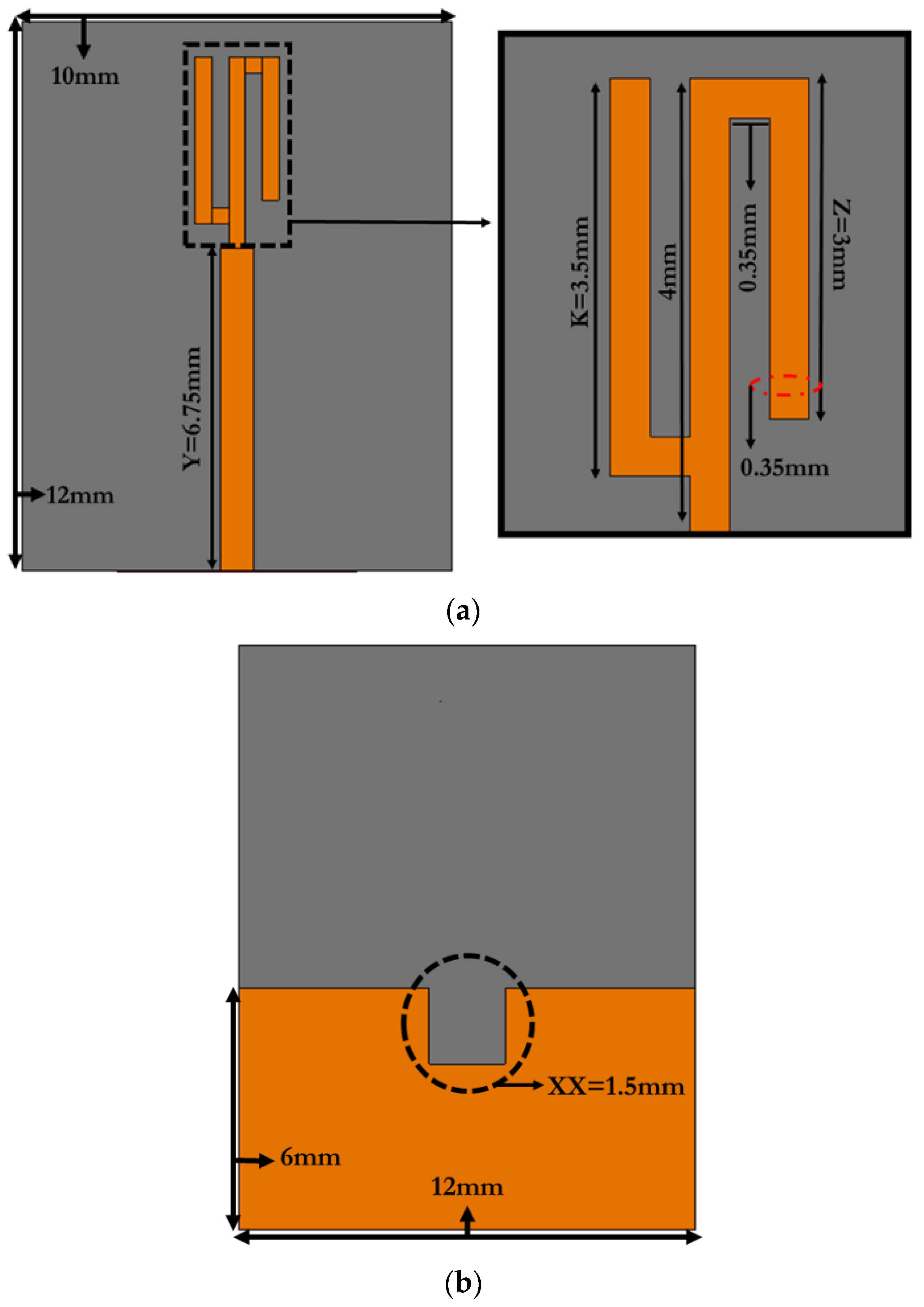
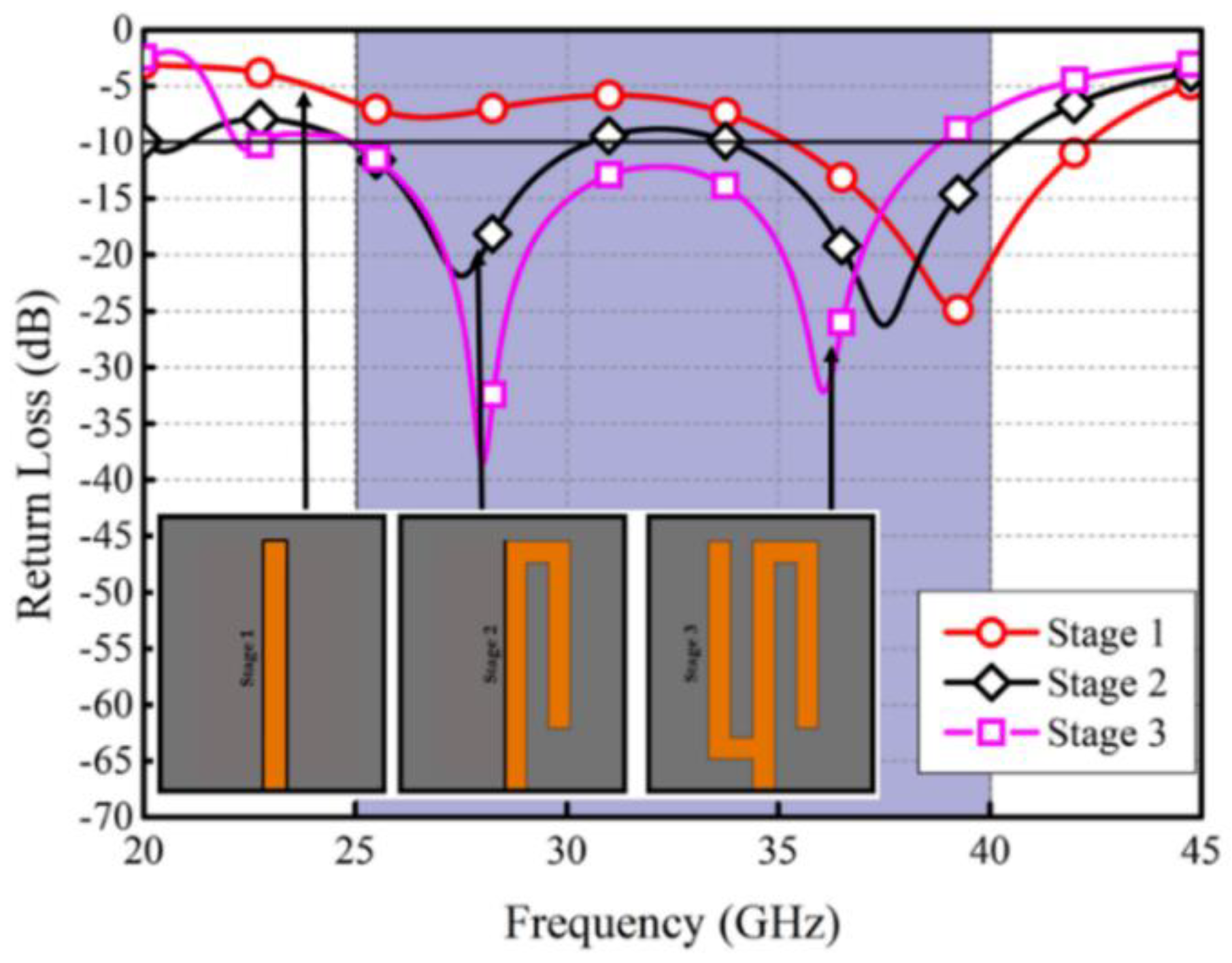
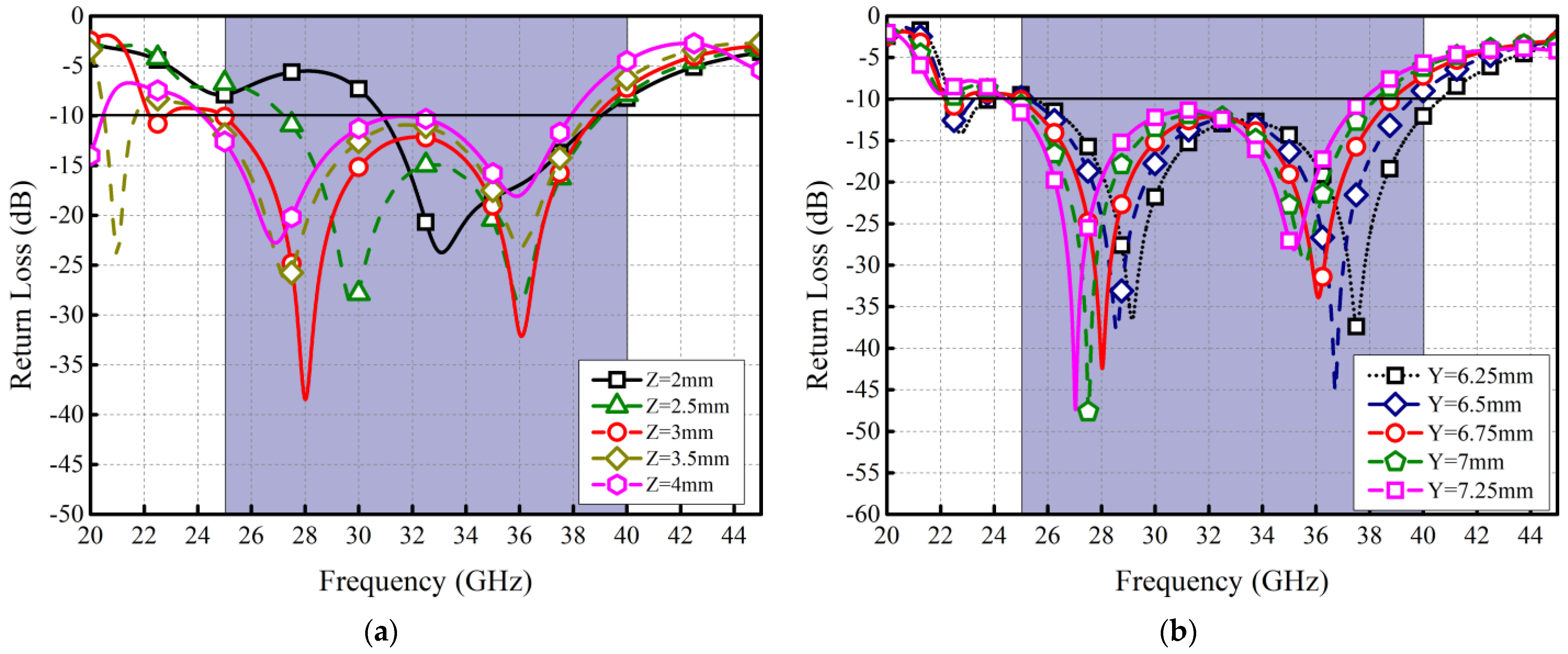
2.1. Single Element
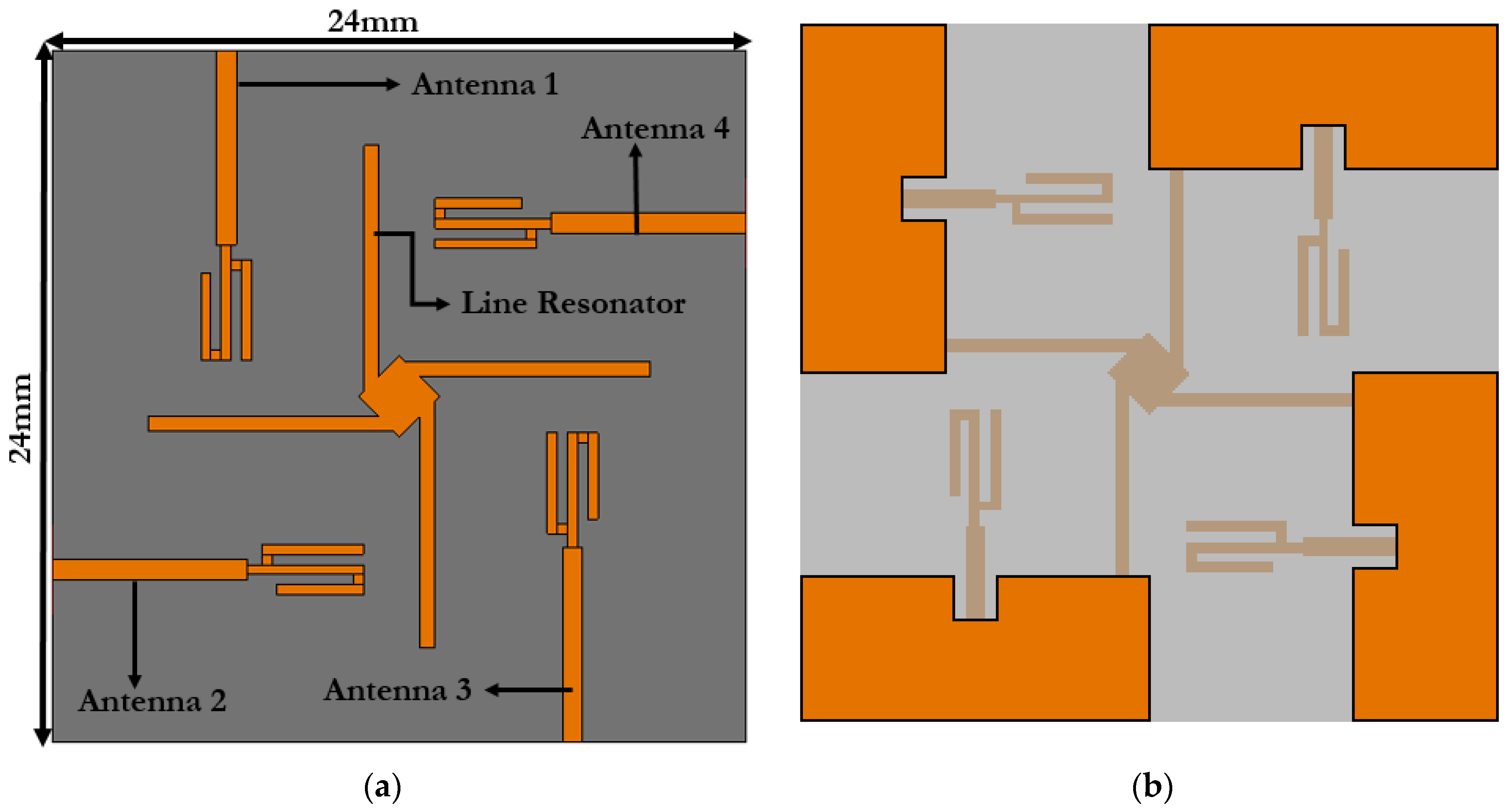
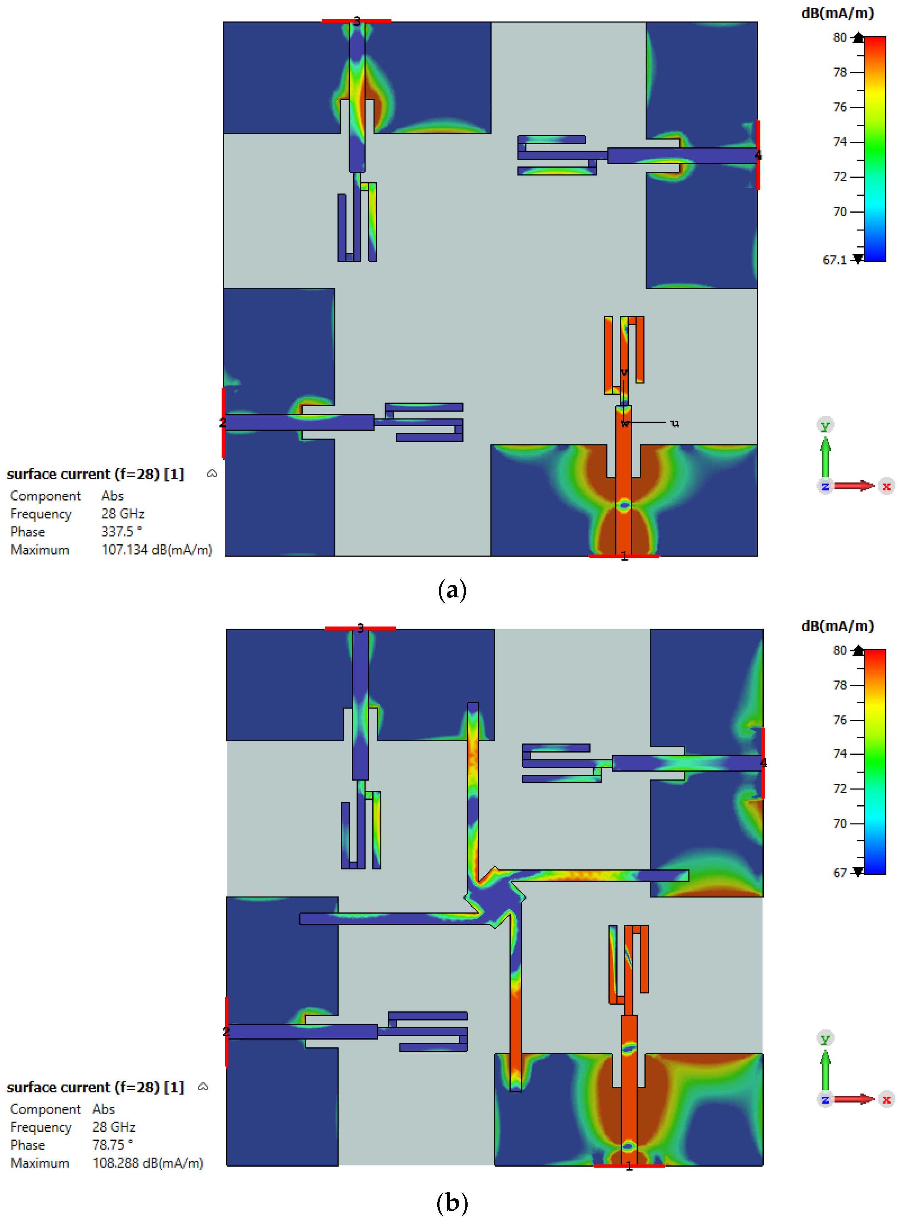
2.2. MIMO Antenna Configuration
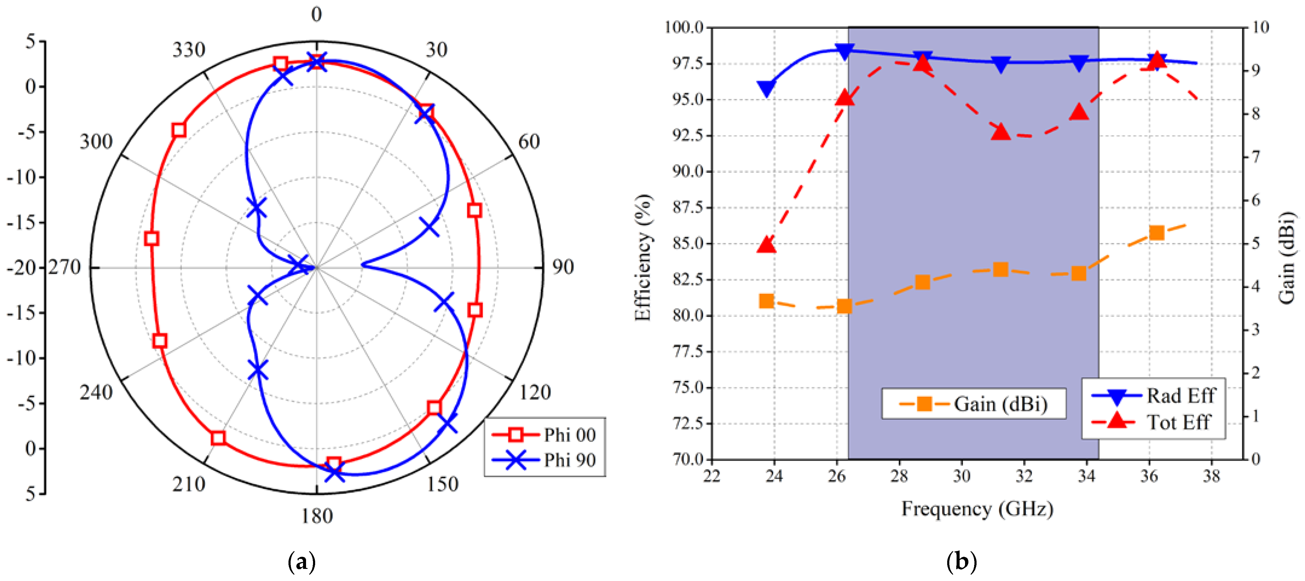
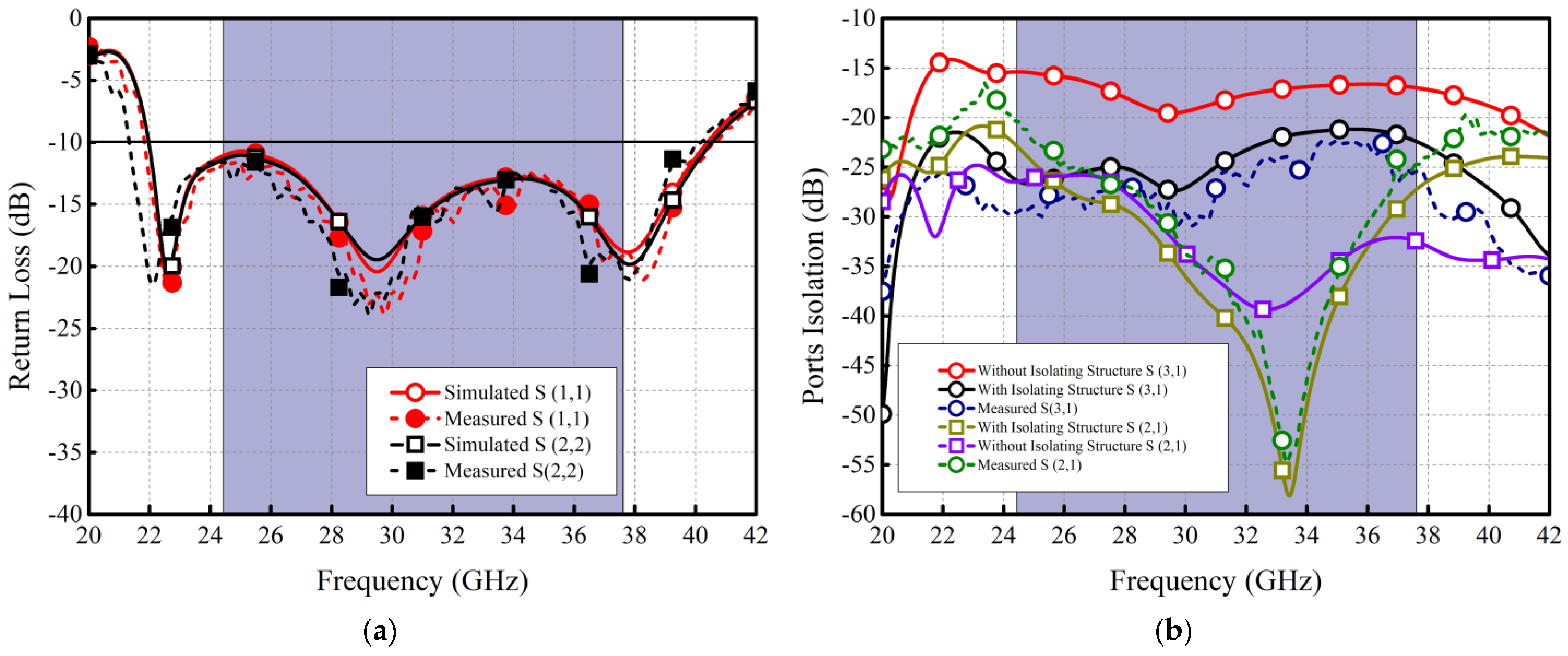
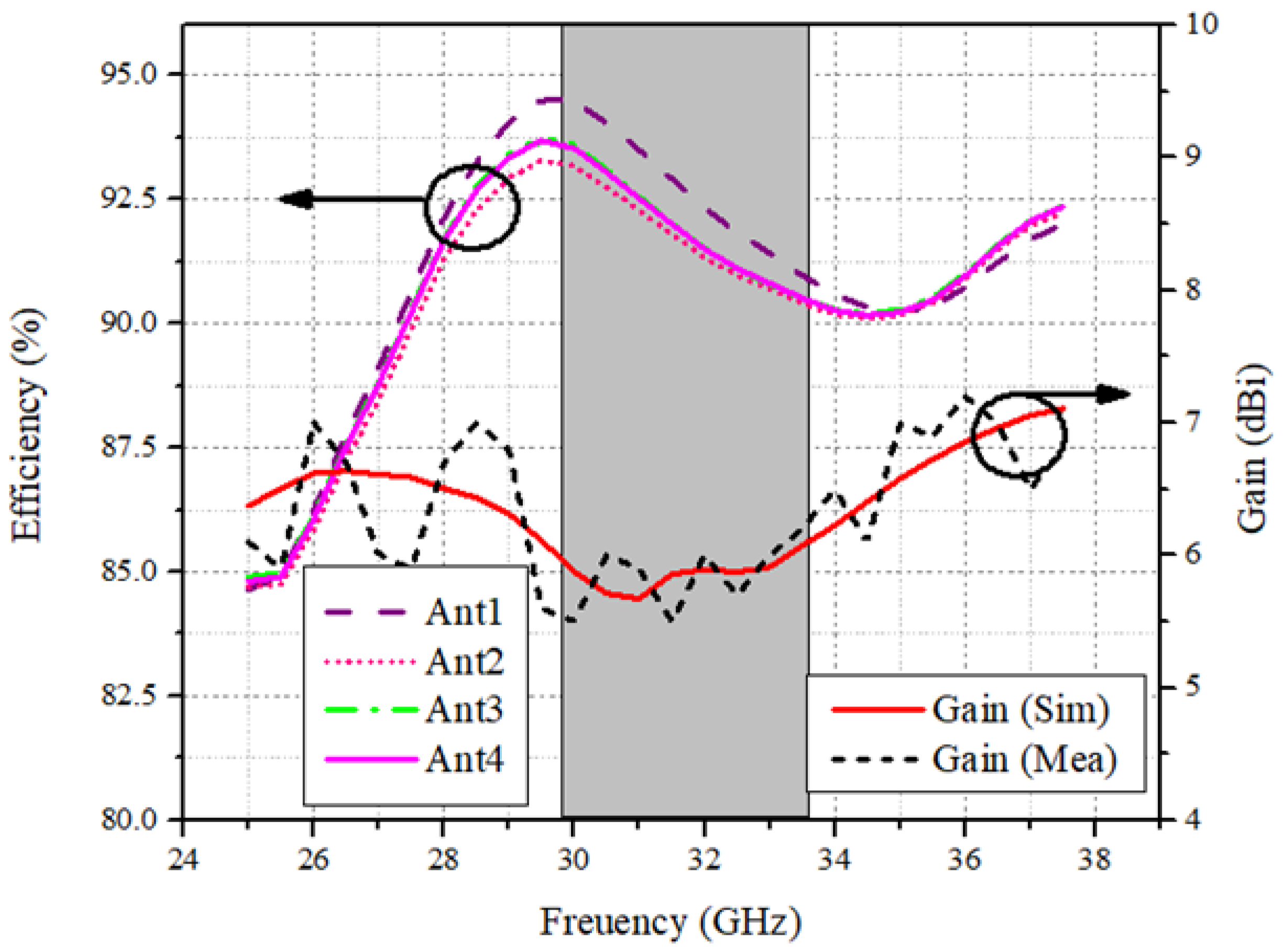
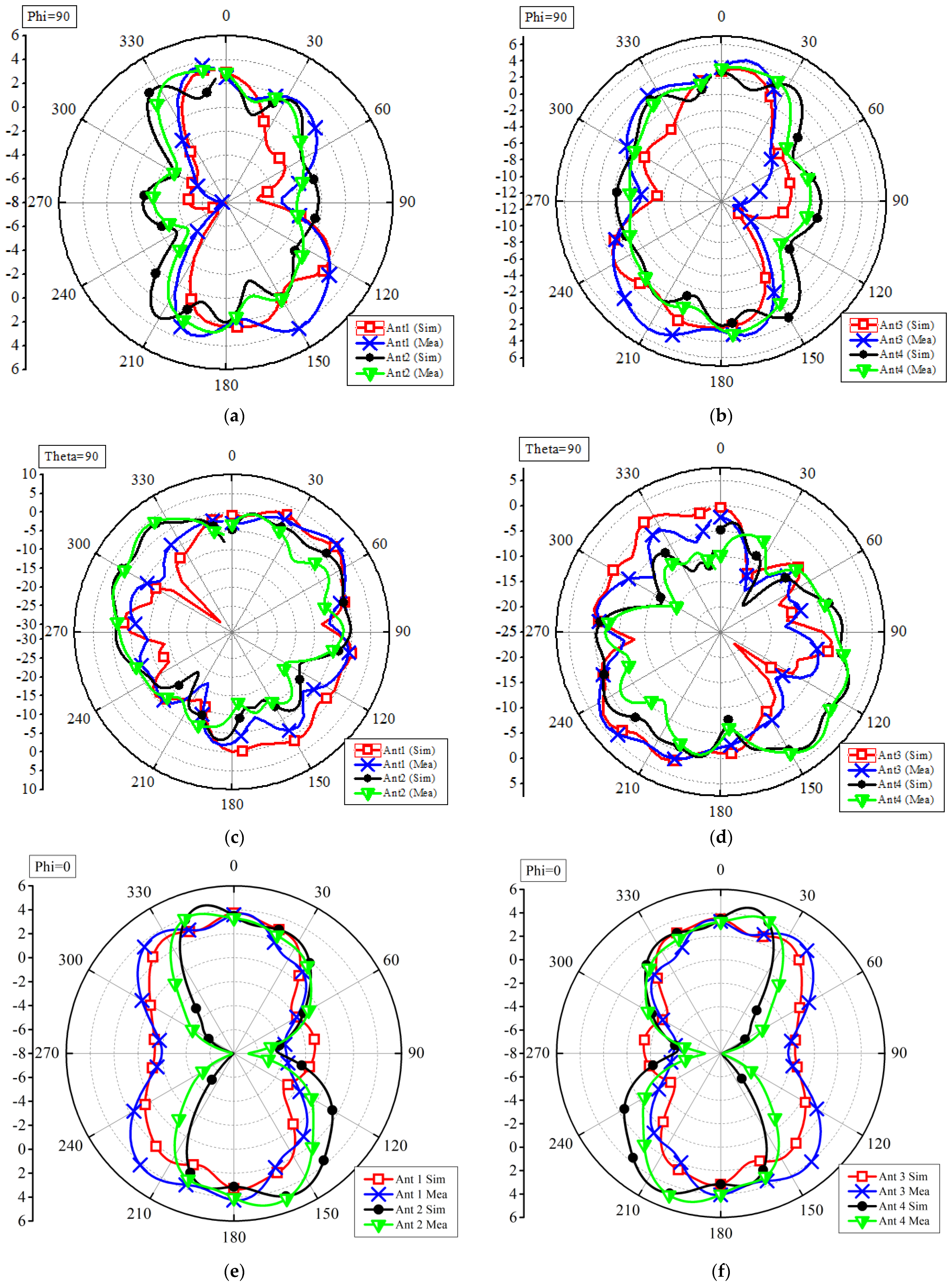
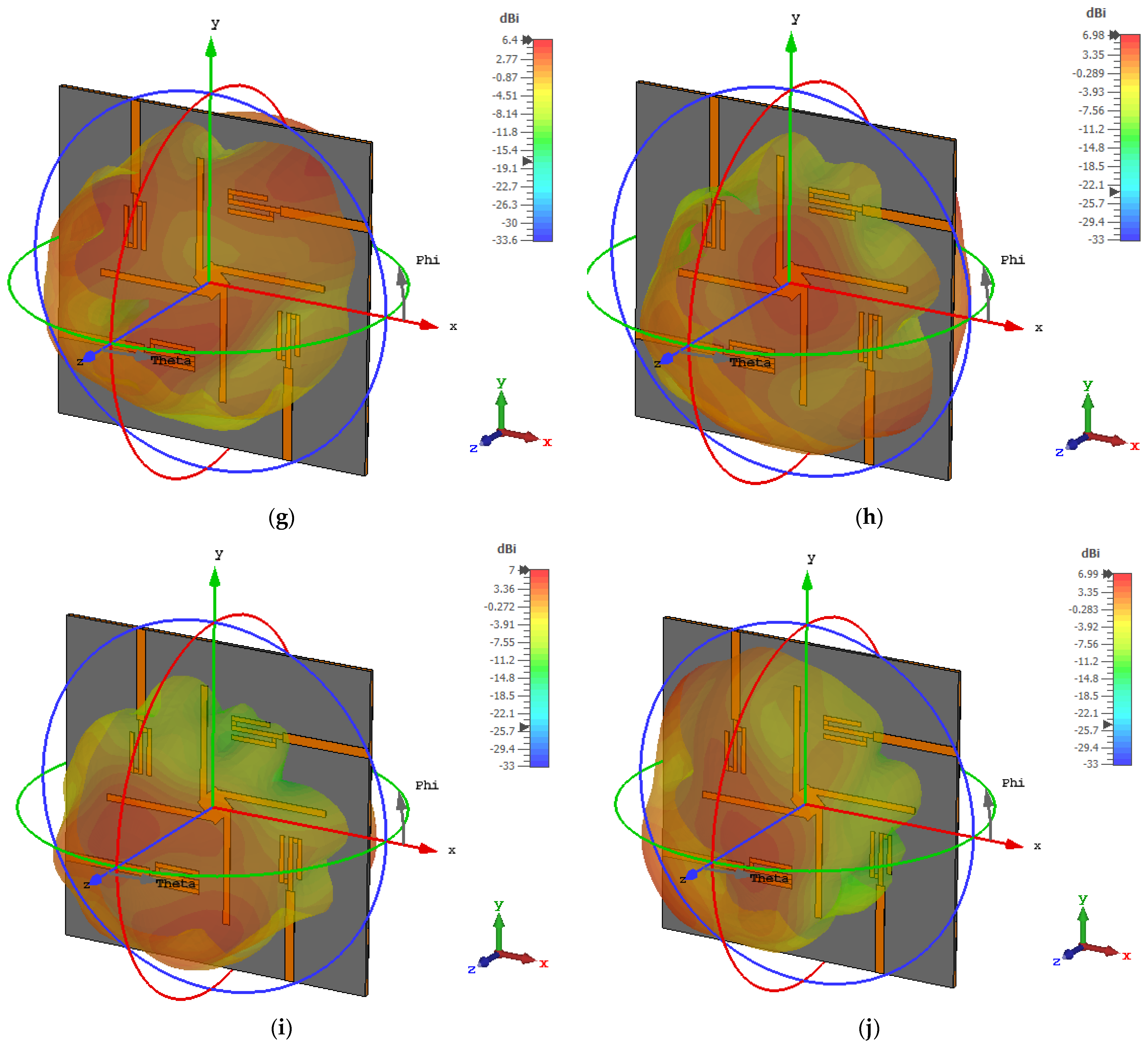
3. Experimental Results
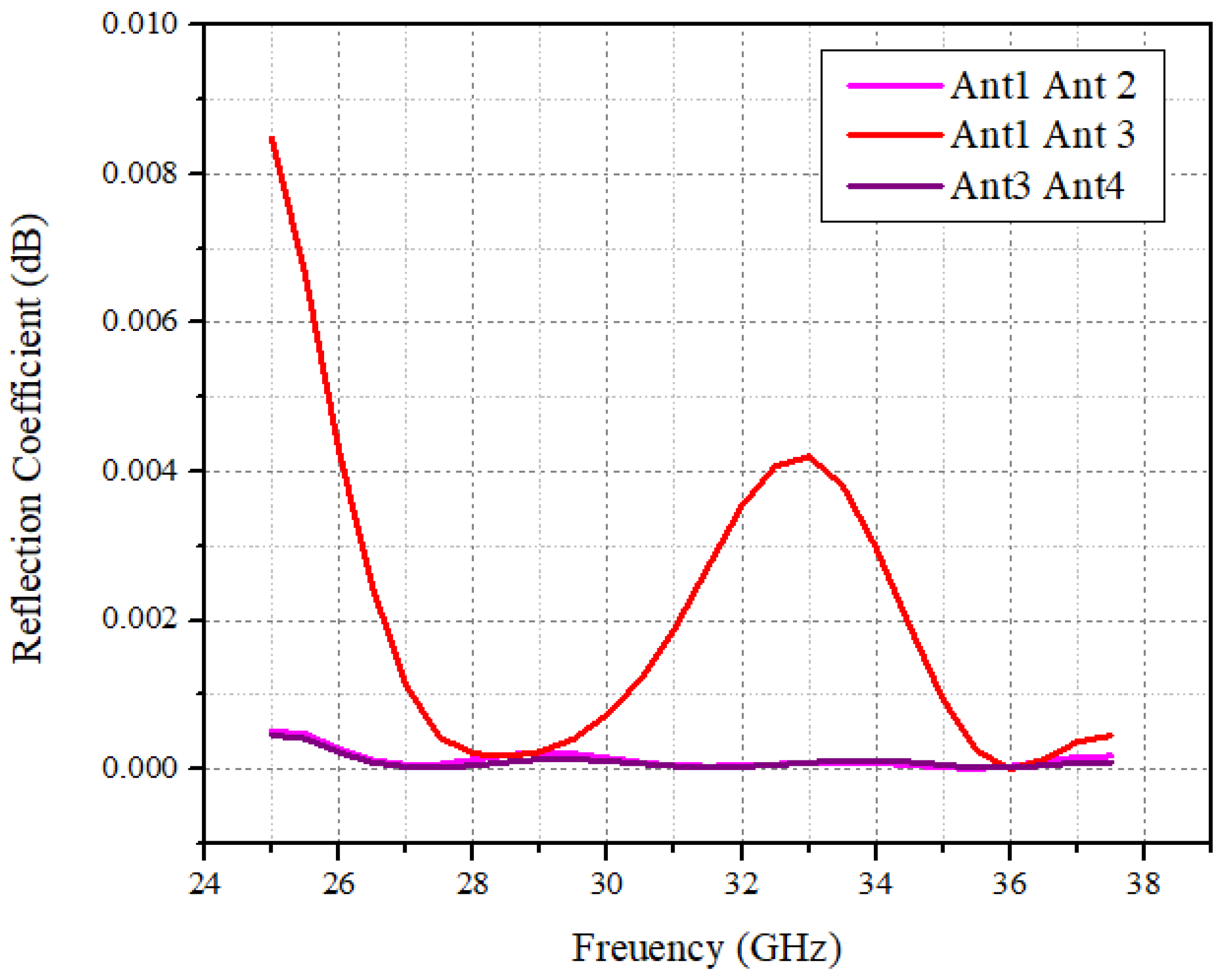
MIMO Parameters
4. Conclusions
Author Contributions
Funding
Institutional Review Board Statement
Informed Consent Statement
Data Availability Statement
Conflicts of Interest
References
- Yang, Q.; Gao, S.; Luo, Q.; Wen, L.; Ban, Y.L.; Ren, X.; Wu, J.; Yang, X.; Liu, Y. Millimeter-wave dual-polarized differentially fed 2-D multibeam patch antenna array. IEEE Trans. Antennas Propag. 2020, 68, 7007–7016. [Google Scholar] [CrossRef]
- Park, S.J.; Shin, D.H.; Park, S.O. Low side-lobe substrate-integrated-waveguide antenna array using broadband unequal feeding network for millimeter-wave handset device. IEEE Trans. Antennas Propag. 2015, 64, 923–932. [Google Scholar] [CrossRef]
- Abdullah, M.; Kiani, S.H.; Iqbal, A. Eight element multiple-input multiple-output (MIMO) antenna for 5G mobile applications. IEEE Access 2019, 7, 134488–134495. [Google Scholar] [CrossRef]
- Kiani, S.H.; Altaf, A.; Abdullah, M.; Muhammad, F.; Shoaib, N.; Anjum, M.R.; Damaševičius, R.; Blažauskas, T. Eight element side edged framed MIMO antenna array for future 5G smart phones. Micromachines 2020, 11, 956. [Google Scholar] [CrossRef] [PubMed]
- Guo, J.; Cui, L.; Li, C.; Sun, B. Side-edge frame printed eight-port dual-band antenna array for 5G smartphone applications. IEEE Trans. Antennas Propag. 2018, 66, 7412–7417. [Google Scholar] [CrossRef]
- Zhu, Q.; Ng, K.B.; Chan, C.H.; Luk, K.M. Substrate-integrated waveguide-fed array antenna covering 57–71 GHz band for 5G applications. IEEE Trans. Antennas Propag. 2017, 65, 6298–6306. [Google Scholar] [CrossRef]
- Kamal, M.M.; Yang, S.; Ren, X.C.; Altaf, A.; Kiani, S.H.; Anjum, M.R.; Iqbal, A.; Asif, M.; Saeed, S.I. Infinity Shell Shaped MIMO Antenna Array for mm-Wave 5G Applications. Electronics 2021, 10, 165. [Google Scholar] [CrossRef]
- Rahman, S.; Ren, X.C.; Altaf, A.; Irfan, M.; Abdullah, M.; Muhammad, F.; Anjum, M.R.; Mursal, S.N.F.; AlKahtani, F.S. Nature inspired MIMO antenna system for future mmWave technologies. Micromachines 2020, 11, 1083. [Google Scholar] [CrossRef] [PubMed]
- Sehrai, D.A.; Abdullah, M.; Altaf, A.; Kiani, S.H.; Muhammad, F.; Tufail, M.; Irfan, M.; Glowacz, A.; Rahman, S. A Novel High Gain Wideband MIMO Antenna for 5G Millimeter Wave Applications. Electronics 2020, 9, 1031. [Google Scholar] [CrossRef]
- Murthy, N. Improved isolation metamaterial inspired mm-Wave MIMO dielectric resonator antenna for 5G application. Prog. Electromagn. Res. C 2020, 100, 247–261. [Google Scholar] [CrossRef] [Green Version]
- Sehrai, D.A.; Asif, M.; Shoaib, N.; Ibrar, M.; Jan, S.; Alibakhshikenari, M.; Lalbakhsh, A.; Limiti, E. Compact Quad-Element High-Isolation Wideband MIMO Antenna for mm-Wave Applications. Electronics 2021, 10, 1300. [Google Scholar] [CrossRef]
- Raheel, K.; Altaf, A.; Waheed, A.; Kiani, S.H.; Sehrai, D.A.; Tubbal, F.; Raad, R. E-Shaped H-Slotted Dual Band mmWave Antenna for 5G Technology. Electronics 2021, 10, 1019. [Google Scholar] [CrossRef]
- Kiani, S.H.; Altaf, A.; Anjum, M.R.; Afridi, S.; Arain, Z.A.; Anwar, S.; Khan, S.; Alibakhshikenari, M.; Lalbakhsh, A.; Khan, M.A.; et al. MIMO Antenna System for Modern 5G Handheld Devices with Healthcare and High Rate Delivery. Sensors 2021, 21, 7415. [Google Scholar] [CrossRef] [PubMed]
- Luo, Y.; Shen, Y.; Cai, X.; Qian, F.; Xu, S.; Cui, H.; Yang, G. Substrate integrated coaxial line design for mmWave antenna with multilayer configuration. Int. J. RF Microw. Comput. Aided Eng. 2022, 32, e23090. [Google Scholar] [CrossRef]
- Abdullah, M.; Kiani, S.H.; Abdulrazak, L.F.; Iqbal, A.; Bashir, M.A.; Khan, S.; Kim, S. High-performance multiple-input multiple-output antenna system for 5G mobile terminals. Electronics 2019, 8, 1090. [Google Scholar] [CrossRef] [Green Version]
- Ojaroudi, M.; Ojaroudi, N.; Ghadimi, N. Dual band-notched small monopole antenna with novel coupled inverted U-ring strip and novel fork-shaped slit for UWB applications. IEEE Antennas Wirel. Propag. Lett. 2013, 12, 182–185. [Google Scholar] [CrossRef]
- Mishra, S.K.; Gupta, R.K.; Vaidya, A.; Mukherjee, J. A compact dual-band fork-shaped monopole antenna for Bluetooth and UWB applications. IEEE Antennas Wirel. Propag. Lett. 2011, 10, 627–630. [Google Scholar] [CrossRef]
- Dong, Y.; Li, Y.; Yu, K.; Wang, Y. High Isolation Design of a Two-Element Planar UWB-MIMO Monopole Antenna; International Applied Computational Electromagnetics Society Symposium: Firenze, Italy, 2017. [Google Scholar] [CrossRef]


| Frequency (GHz) | MEG1 | MEG2 | MEG3 | MEG4 |
|---|---|---|---|---|
| 28 | −3.50 | −3.21 | −3.26 | −3.10 |
| 29 | −2.99 | −3.06 | −3.61 | −3.11 |
| Refs. | Ant. Elements | Single Element (mm2) | Array (mm2) | Bandwidth | Isolation (dB) | Efficiency (%) | ECC |
|---|---|---|---|---|---|---|---|
| [7] | 4 | 12 × 10 | 30 × 30 | 27–30 | 28 | 84 | <0.1 |
| [8] | 4 | 12 × 10 | 30 × 30 | 26–30 | 24 | 82 | <0.2 |
| [9] | 4 | 20 × 20 | 80 × 80 | 23–40 | 26 | 85 | <0.01 |
| [12] | 4 | 15 × 10 | 20 × 20 | 27.5–28.5/37.5–38.5 | 24 | 80 | <0.1 |
| [16] | 1 | 12 × 18 | N/A | 3–12 | N/A | N/A | N/A |
| [17] | 1 | 42 × 24 | N/A | 3–12 | N/A | N/A | N/A |
| [18] | 2 | N/A | 35 × 52 | 3.28–12 | 20 | N/A | N/A |
| Proposed | 4 | 10 × 12 | 24 × 24 | 24–39 | 26 | 92 | <0.05 |
Publisher’s Note: MDPI stays neutral with regard to jurisdictional claims in published maps and institutional affiliations. |
© 2022 by the authors. Licensee MDPI, Basel, Switzerland. This article is an open access article distributed under the terms and conditions of the Creative Commons Attribution (CC BY) license (https://creativecommons.org/licenses/by/4.0/).
Share and Cite
Khan, M.A.; Al Harbi, A.G.; Kiani, S.H.; Nordin, A.N.; Munir, M.E.; Saeed, S.I.; Iqbal, J.; Ali, E.M.; Alibakhshikenari, M.; Dalarsson, M. mmWave Four-Element MIMO Antenna for Future 5G Systems. Appl. Sci. 2022, 12, 4280. https://doi.org/10.3390/app12094280
Khan MA, Al Harbi AG, Kiani SH, Nordin AN, Munir ME, Saeed SI, Iqbal J, Ali EM, Alibakhshikenari M, Dalarsson M. mmWave Four-Element MIMO Antenna for Future 5G Systems. Applied Sciences. 2022; 12(9):4280. https://doi.org/10.3390/app12094280
Chicago/Turabian StyleKhan, Muhammad Abbas, Abdullah G. Al Harbi, Saad Hassan Kiani, Anis Nurashikin Nordin, Mehr E Munir, Sohail Imran Saeed, Javed Iqbal, Esraa Mousa Ali, Mohammad Alibakhshikenari, and Mariana Dalarsson. 2022. "mmWave Four-Element MIMO Antenna for Future 5G Systems" Applied Sciences 12, no. 9: 4280. https://doi.org/10.3390/app12094280
APA StyleKhan, M. A., Al Harbi, A. G., Kiani, S. H., Nordin, A. N., Munir, M. E., Saeed, S. I., Iqbal, J., Ali, E. M., Alibakhshikenari, M., & Dalarsson, M. (2022). mmWave Four-Element MIMO Antenna for Future 5G Systems. Applied Sciences, 12(9), 4280. https://doi.org/10.3390/app12094280