Article

Quasi-Isotropic Hybrid Dielectric Resonator Antenna—Bow-Tie Patch with Harmonic Suppression

Department of Electrical and Computer Engineering, Sungkyunkwan University, Suwon 16419, Korea
*
Author to whom correspondence should be addressed.
Appl. Sci. 2022, 12(8), 3842; https://doi.org/10.3390/app12083842
Submission received: 19 March 2022 / Revised: 8 April 2022 / Accepted: 8 April 2022 / Published: 11 April 2022

Abstract

:
This paper proposes a quasi-isotropic hybrid dielectric resonator antenna (DRA) and bow-tie patch with harmonics suppression. The suggested antenna consists of a DRA, a bow-tie patch, and a microstrip seventh-order Chebyshev low-pass filter. By loading a bow-tie patch on the designed DRA, a quasi-isotropic pattern is realized. The seventh-order Chebyshev low-pass filter was applied to the feed line, and harmonics were reduced in the section separate to the operating band to remove harmonics generated by the proposed antenna. The simulated S 11 that satisfies below −10 dB is 3.09–3.3 GHz (6.25%), and the measured S11 is 3.10–3.28 GHz (5.64%). The simulated gain difference considering all radiating regions ( 0 φ 360 and 0 θ 180 ) is 7.211 dB. Compared with the antenna without a filter, the harmonic gain was reduced by 10.847 and 15.774 dB. The measured gain isolation of the operating band and the second and third harmonics are 10.10 and 18.94 dB, respectively. The proposed antenna is considered to be applicable to applications that require radio wave reception in all directions such as wireless point access points, internet of things and radio frequency identification, and is expected to contribute to reducing the size of the RF system.

1. Introduction

Because the isotropic pattern can be transmitted to and received from all directions, it can be applied to various communication fields, such as radio frequency identification, wireless access points, and the internet of things, thereby increasing interest in isotropic antennas. However, realistically, it is impossible to realize an ideal isotropic radiation pattern that covers all directions; therefore, various studies have been conducted to implement a quasi-isotropic pattern [1,2,3,4,5,6,7]. Two omnidirectional patterns that have an orthogonal relationship are required to implement a quasi-isotropic pattern. A method of implementing a quasi-isotropic pattern by placing two electric field dipole antennas in a mechanically orthogonal state exists [2,3,4]. Furthermore, a method of implementing a quasi-isotropic pattern using an electric field dipole and a magnetic field dipole having a complementary relationship exists [5,6,7]. In previous studies [2,3,4], a quasi-isotropic pattern was realized by physically crossing two electric field dipoles. In another study [5], a quasi-isotropic pattern was implemented by making orthogonal electric and magnetic field dipoles using loops formed on the folded dipole and ground. An electric field dipole was implemented in the feeding structure of the loop antenna, and a quasi-isotropic pattern is implemented using a magnetic field dipole in the loop antenna in a previous study [6]. In the literature [7], a quasi-isotropic pattern was implemented using a dielectric resonator antenna (DRA) and a small ground. Here, DRA is equivalent to a magnetic field dipole. The small ground is equivalent to an electric field dipole, and the quasi-isotropic pattern is realized by synthesizing these two radiation patterns. However, since the study mentioned above has not considered radiation by harmonics other than the operating band, interference with other communication equipment may occur.
In general, a filter structure is also used outside the antenna to suppress interference with communication equipment at other frequencies. However, this additional structure increases the system size, fabrication cost, and insertion loss [8]. Various research projects focusing on antennas with a harmonic suppression function are being conducted to solve this problem. For example, studies on integrating harmonic filters into antennas [9,10,11,12,13], using impedance transformers [14,15], using harmonic canceling techniques [16], and using defected ground structures (DGS) [17,18,19] have been conducted. The authors of [9] used a coaxial line-type sixth-order Chebyshev low-pass filter as the feed structure for the cavity-back patch antenna to eliminate the generated harmonics. In [10], harmonics generated in a section other than the operating band were eliminated by implementing a coupled line-type bandpass filter in the ground region of the DRA. The authors of the paper [11] designed a multilayer consisting of a radiator, filtering, and slot stage and integrated a filter and antenna to suppress harmonics. In studies [12,13], suppressing harmonics by implementing a notch filter in a T-shaped feeding structure and suppressing harmonics using a low-pass filter with ferrite are presented. The study [14] suppressed the harmonics of the patch antenna using a λ / 4 transformer and a shorting pin. The author of the thesis [15] removed the harmonics by integrating an impedance transformer that matches the impedance in the operating band and mismatches the impedance in the harmonic band into the antenna. In the study [16], harmonics were canceled by adding a λ / 4 stub of harmonic frequency to generate a field with an inverse phase of harmonics. In References [17,18,19], harmonics are suppressed by adding a slit or stub to the ground and feed line of the antenna.
However, since the harmonic suppression function is implemented for an antenna with a unidirectional or omnidirectional pattern, research on an antenna with a quasi-isotropic pattern and a harmonic suppression function is required.
In this paper, a quasi-isotropic hybrid DRA and bow-tie patch with harmonic suppression is proposed. DRA and bow-tie patch antennas were used to implement the quasi-isotropic pattern. The seventh-order Chebyshev low-pass filter was designed in the feed line of the proposed antenna to remove harmonics. This paper is organized as follows: Section 2 first explains the principle of implementing the quasi-isotropic pattern, the configuration of the proposed antenna, and the antenna design parameters. Second, the filter design method and changes in filter characteristics for the filter order are described. Finally, when the filter and the antenna are integrated, a study was conducted on how much the filter affects the realization of a quasi-isotropic pattern. CST of a microwave studio was utilized to design the proposed antenna and analyze the radiation pattern and distribution of the electric field. Section 3 shows the comparison between the measured and simulated results after the proposed antenna is fabricated. The conclusion is presented in Section 4.

2. Design of Proposed Quasi-Isotropic Hybrid Dielectric Resonator Antenna-Bow-Tie Patch with Harmonics Suppression

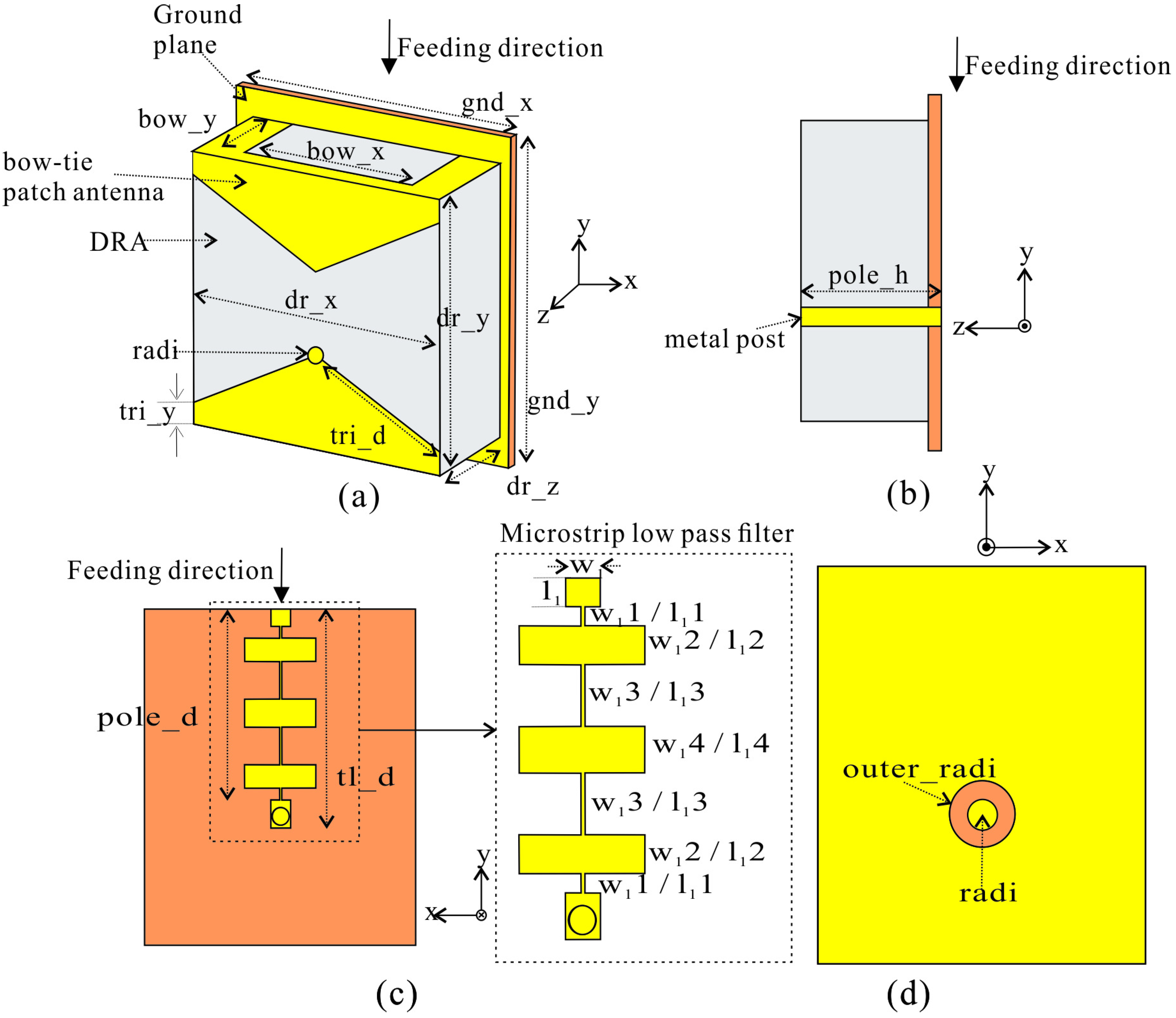
2.1. Design of Proposed Antenna Having a Quasi-Isotropic Pattern

Figure 1 shows the configuration of the proposed antenna. The bow-tie patch is loaded into the DRA to implement the quasi-isotropic pattern. The microstrip seventh-order Chebyshev low-pass filter is used in the feed line to suppress harmonics. Here, the DRA and bow-tie patch antenna is simultaneously fed by the metal post located at pole_d from the feeding direction and has a length of pole_h and is electrically connected to the microstrip filter located in the feeding line. Operating in the TM01 mode, the DRA is equivalent to a vertical dipole and the bow-tie patch is equivalent to a horizontal dipole to realize a quasi-isotropic pattern. The DRA and the ground size were 39 × 40.18 × 16.76 mm 3 and 40.6 × 49.4 mm 2 , respectively. The substrate used was Taconic RF-35 ( ε = 3.5, t a n δ = 0.0025), and the thickness was 1.52 mm. The alumina ( ε = 9.6, t a n δ = 0.0002) was used to design DRA. The design parameters are presented in Table 1.
Figure 2 shows the principle of implementing the quasi-isotropic pattern of the proposed antenna. As mentioned above, to implement a quasi-isotropic pattern, two omnidirectional patterns that have an orthogonal relationship are required. Figure 2a shows the DRA and bow-tie patch antenna used to implement the quasi-isotropic pattern in this paper. The metal post inside the DRA feeds the DRA and the bow-tie patch antenna, creating E 1 and E 2 fields, respectively. The E 1 and E 2 fields are orthogonal to each other, and as shown in Figure 2b, an omnidirectional pattern that has an orthogonal relationship is implemented. Therefore, two omnidirectional patterns that have an orthogonal relationship are synthesized to realize a quasi-isotropic pattern.

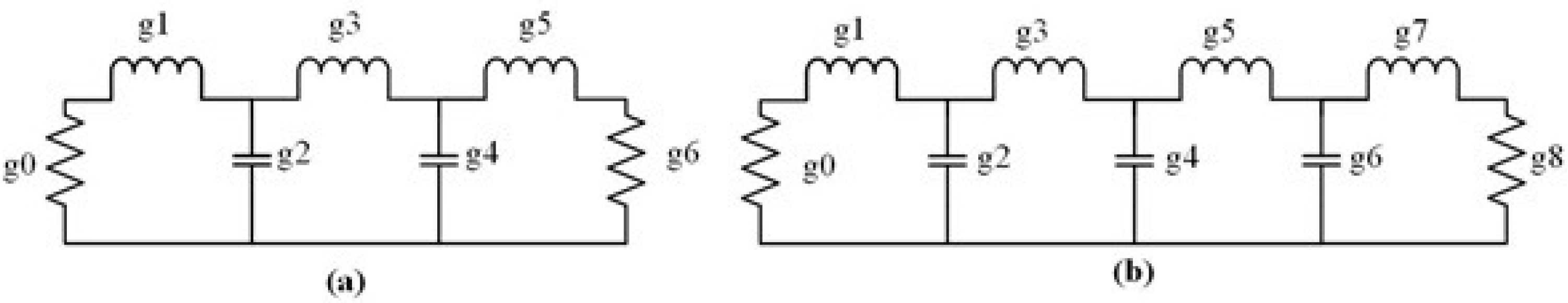
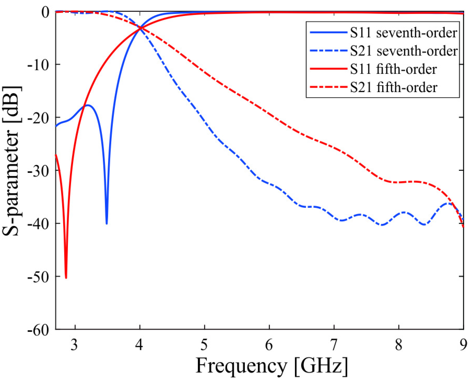
2.2. Design of the Filter for Harmonic Suppression

Figure 3 shows the configuration of the fifth- and seventh-order Chebyshev low-pass filters designed to suppress harmonics generated by the proposed antenna and the location where the filter is to be integrated with the feeding part of the proposed antenna. Therefore, the low-pass filter was designed in consideration of the feed line of the proposed antenna. Chebyshev coefficients must be derived to design a Chebyshev filter. We derived the fifth- and seventh-order Chebyshev low-pass filters response coefficients by referring to the literature [20], and the Chebyshev response coefficients are presented in Table 2.
Figure 4 shows the equivalent circuit of the Chebyshev low-pass filter, and the response coefficient of Chebyshev can be equivalent to a resistor, an inductor, or a capacitor. To convert the inductor and capacitor into a distributed component, an electrical line length that satisfies the Chebyshev response coefficients of the inductor and capacitor is derived by using Equations (1) and (2) [21]. Based on the induced electrical line length, a physical transmission line length corresponding to the Chebyshev response coefficient of each lumped component is derived. Here, β is the wavenumber ( 2 π / λ g ), and L and C are Chebyshev response coefficients corresponding to inductors and capacitors, respectively. R 0 was defined as 50 Ω as a characteristic impedance, and Z h and Z l were defined as 120 and 20 Ω , respectively. The λ g was set so that the cutoff frequency was 4 GHz, and the filter design parameters were derived by using Equations (1) and (2). Table 3 shows the design parameters of the fifth- and seventh-order Chebyshev low-pass filters with the cutoff frequency set to 4 GHz.
β l = L R 0 Z h ( i n d u c t o r )
β l = C Z l R 0 ( c a p a c i t o r ) .
Figure 5 shows the simulated S parameters ( S 11 and S 21 ) of the fifth- and seventh-order Chebyshev low-pass filters. As a result of comprehensively examining the filter characteristics presented in Figure 5, the seventh-order Chebyshev low-pass filter is larger than the fifth-order Chebyshev low-pass filter. However, the filter has excellent skirt characteristics and high isolation between bands. In this paper, harmonics are suppressed using a seventh-order Chebyshev low-pass filter. A high-order filter is required to suppress harmonics in the operating band’s adjacent region and has high isolation between bands. Since the filter size increased when the filter order increased, the filter was designed so that the size of the filter coincides with the size of the feed line of the proposed antenna.

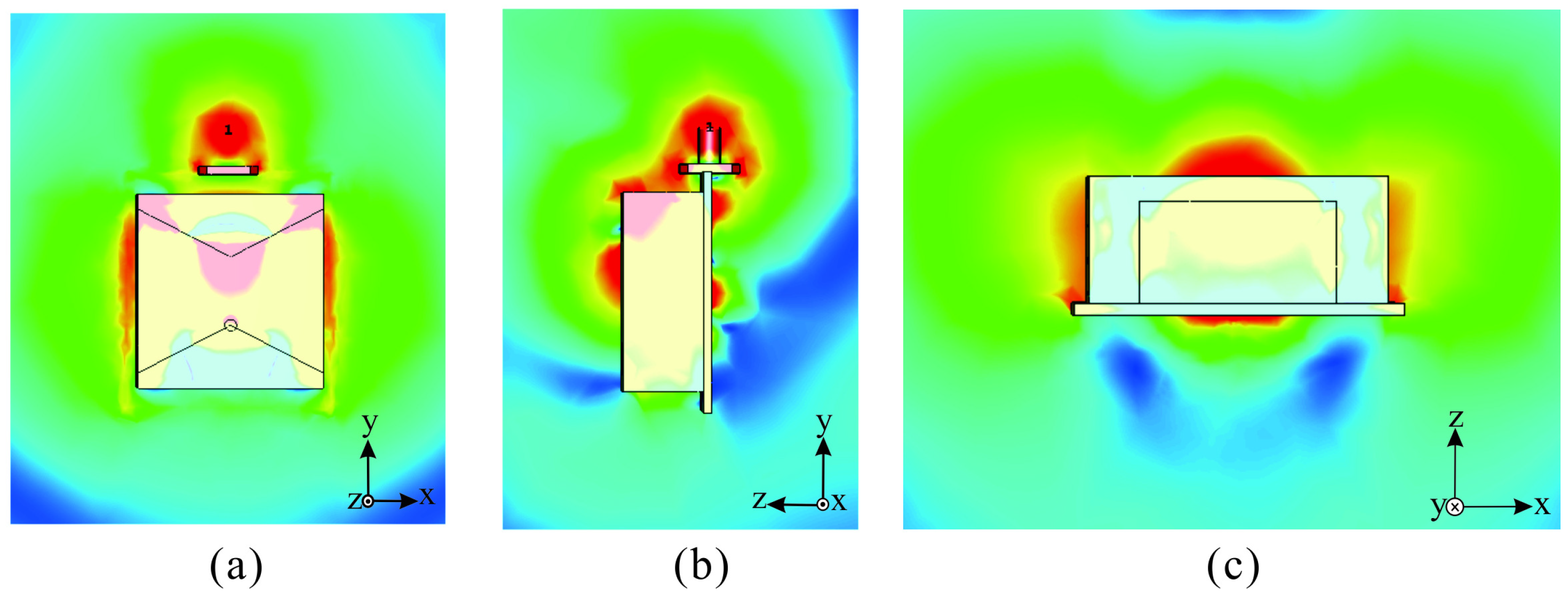
2.3. Simulated Result Analysis of the Proposed Antenna

Figure 6 shows the comparison of S 11 and the maximum gain of the proposed antenna with harmonic suppression and the antenna without harmonic suppression. The simulated S11 (≤−10 dB) bands of the antenna without a filter and the proposed antenna are 3.06–3.33 GHz (8.45%) and 3.09–3.3 GHz (6.25%), respectively. The gain in the operating band of the proposed antenna is the same as that of the antenna without a filter, and the maximum gain difference is prominent in the harmonic region, confirming that the filter effectively suppresses harmonics. In addition, it can be confirmed that the harmonics outside the operating band are sufficiently suppressed in the proposed antenna.
Table 4 shows the gain concerning the operating band and harmonics of the antenna without a filter and the proposed antenna. The gain of the proposed antenna in the operating band is approaching that equal to the antenna’s gain without a filter. Compared with the antenna without a filter, the operating band and isolation from harmonics were 9.781 and 13.272 dB, respectively. In addition, the gain of the second and third harmonics of the proposed antenna decreased by 10.847 and 15.774 dB, respectively, compared with the antenna without a filter. Therefore, it can be confirmed that the filter sufficiently suppresses harmonics.
Figure 7 is an analysis of the effect of the integrated filter on realizing the quasi-isotropic pattern. After the filter was integrated, the band realizing the quasi-isotropic pattern was reduced. The reason is that the minimum gain from 3.2 to 3.3 GHz is reduced while the filter’s cutoff frequency is reduced to suppress harmonics adjacent to the operating band. The gain difference of the proposed antenna is increased in the 3.2–3.3 GHz band compared with the antenna without a filter. When the cutoff frequency of the filter is set to high, the band of the quasi-isotropic pattern increases; however, the suppression of adjacent harmonics is weakened, so an appropriate tradeoff is required in designing the antenna with a filter.
In this paper, the proposed antenna was designed so that the gain difference from 3.1 to 3.18 GHz had a value less than 10 dB. The simulated gain difference ( 0 φ 360 and 0 θ 180 ) at 3.1, 3.13, and 3.15 GHz of the proposed antenna is 7.211, 7.422, and 8.24 dB, respectively.
The radiation pattern of the antenna without a filter and the proposed antenna were compared to analyze whether the integrated filter affects the radiation pattern. Figure 8 displays the radiation patterns of the proposed antenna at 3.1, 3.13, and 3.15 GHz. Since the two antennas implemented a quasi-isotropic radiation pattern covering all areas, it was confirmed that the filter’s effect on implementing the quasi-isotropic pattern was minimal.
Figure 9 shows the electric field distribution of the proposed antenna. The electric field is radiated in all areas, and it can be seen that the electric field is particularly concentrated in the +y-axis direction. This is because the electric field is scattered by the SMA port of the conductor component located in the +y-axis direction. On the other hand, it can be seen that the magnitude of the electric field in the −y-axis direction without the SMA port is relatively low. In addition, it can be seen that the magnitude of the electric field in the −z axis direction is relatively low. This is because some electric fields are reflected by the ground of the proposed antenna.

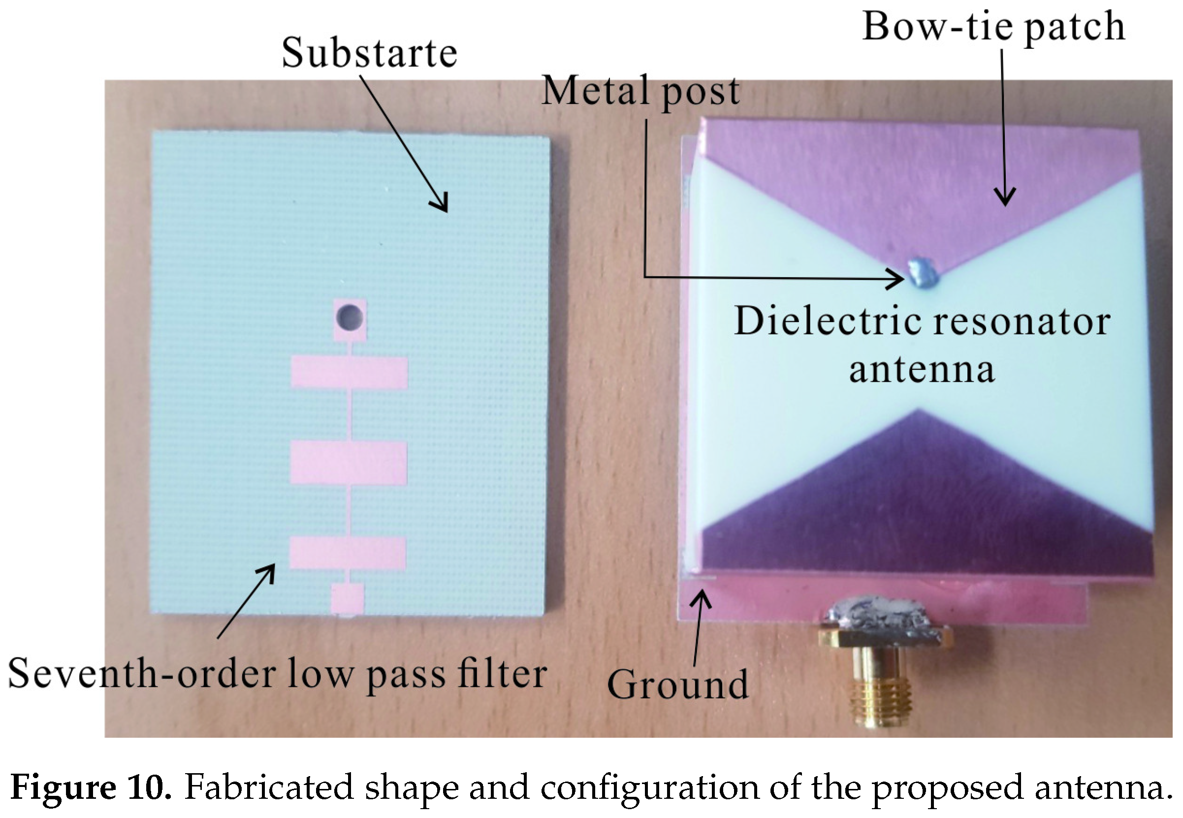
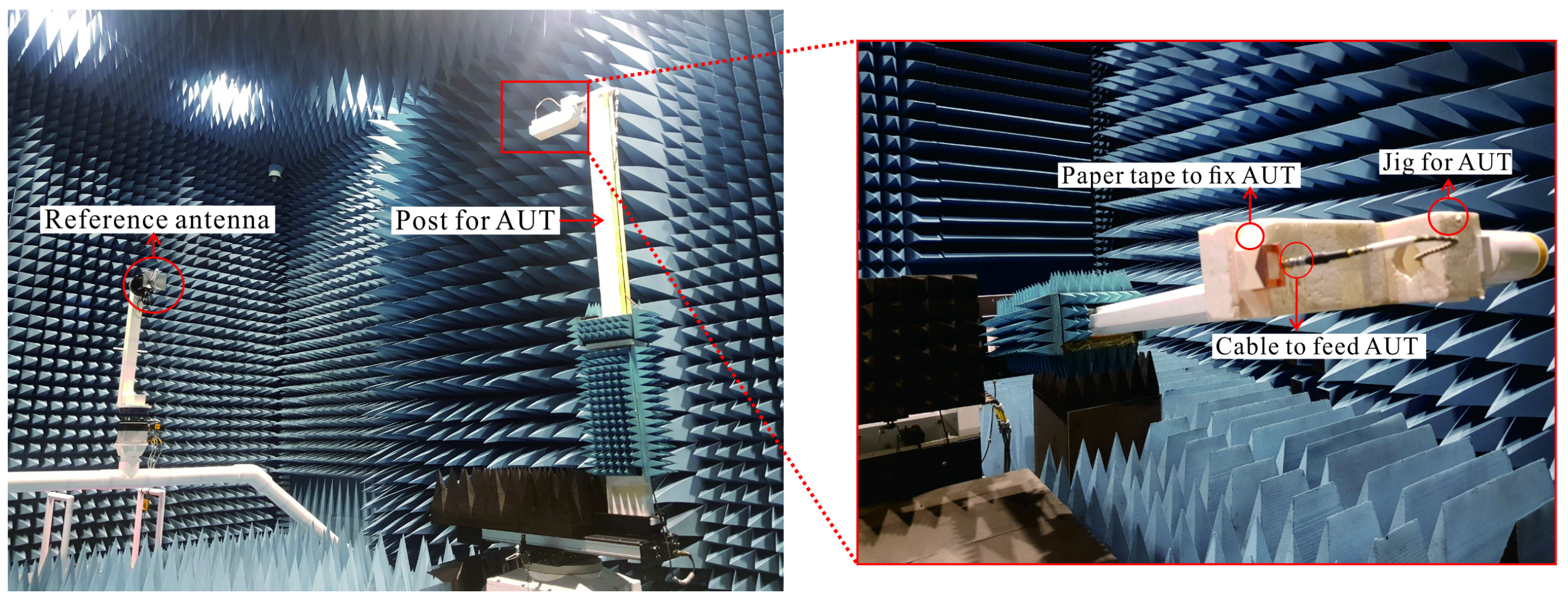
3. Fabrication and Measurement

Figure 10 shows the fabricated shape and configuration of the proposed antenna, which consists of a DRA, a bow-tie patch, and a low-pass filter. The DRA is attached to the ground and the substrate’s upper surface, then power is fed through a low-pass filter located on the lower surface of the substrate. The bow-tie patch is applied with copper tape and attached to the DRA. A hole is drilled in the DRA, and a metal post is inserted to power the bow-tie and DRA simultaneously. It is electrically connected to the low-pass filter located on the lower surface of the substrate.
Figure 11 is a graph comparing the measured and simulated S11 of the fabricated antenna. For the S11 measurement of the proposed antenna, the HP8510C network analyzer was used; the measured S11 band satisfying −10 dB or less was 3.10–3.28 GHz (5.64%) and the simulated S11 band was 3.09–3.3 GHz (6.25%). The simulated S11 and the measured S11 results agree. In addition, it was confirmed that the integrated filter sufficiently suppresses harmonics other than the operating band.
Figure 12 shows the measurement environment of the anechoic far-field chamber to measure the radiation pattern of the manufactured antenna. The manufactured antenna is loaded on the jig, and paper tape is used to fix the antenna during the measurement process. The antenna fabricated through the feed cable is excited, and the radiation pattern is measured while the post and the jig are mechanically rotated. In the pattern measurement section, φ ranges from 0 to 360 , θ ranges from 0 to 180 .
Figure 13 shows the radiation patterns of the xz, yz, and xy planes at 3.1, 3.13, and 3.15 GHz, respectively, in the anechoic far-field chamber. The post and jig’s presence on the −z axis causes a slight difference in the shape of the measured and simulated radiation patterns of the back radiation of the proposed antenna. However, it was confirmed that a sufficiently uniform gain was secured to cover all directions in the measured and simulated radiation patterns.
Table 5 shows the simulated and measured gain difference. To remove the influence of post and jig on the −z axis on the radiation pattern, the range of the radiation pattern was set as 0 φ 360 and 0 θ 90 . In the case of the maximum gain, it was confirmed that the simulated and measured results had similar values, but in the case of the minimum gain, a difference of approximately 2 dB occurred. The reason is the influence of the unshielded feed cable and tools for measuring the radiation patterns. However, both results display a sufficiently uniform gain in the presented radiation section.
Figure 14 shows the comparison between the measured and simulated maximum gain according to frequency. The measurement and simulation results agree, and harmonics are suppressed in the section other than the operating band. The simulated gain isolation between the operating band and the second and third harmonics are 11.20 and 14.69 dB, respectively, and the measured gain isolation is 10.10 and 18.94 dB, respectively. Therefore, it was confirmed that radiation by harmonics was sufficiently suppressed.

4. Conclusions

In this paper, a quasi-isotropic hybrid DRA and bow-tie patch with harmonic suppression is proposed. The DRA and bow-tie patch antenna were utilized to implement the quasi-isotropic pattern. The quasi-isotropic pattern was realized by combining two omnidirectional patterns with an orthogonal relationship. For harmonic suppression, a seventh-order Chebyshev low-pass filter was designed in the feed line of the proposed antenna. In the case of the antenna without a filter, harmonic radiation occurred in a section separate from the operating band. However, the proposed antenna effectively removed harmonics generated in a section away from the operating band, suppressing the radiation due to harmonics. The measured gain isolations of the second and third harmonics of the proposed antenna are 10.10 and 18.94 dB, respectively, and the simulated gain difference considering all radiation areas ( 0 φ 360 and 0 θ 180 ) is at least 7.211 dB. Therefore, the proposed antenna applies to various wireless communication fields and is expected to improve the size and performance of the RF-system.

Author Contributions

Conceptualization, T.J. and K.C.H.; methodology, T.J. and J.H.K.; software, T.J.; validation, T.J. and J.S.L.; formal analysis, T.J. and J.P.; investigation, T.J., D.H.H.; filter analysis T.J., D.G.L. and K.C.H.; resources, T.J.; data curation, T.J.; draft preparation, T.J.; writing—review and editing, T.J. and K.C.H.; supervision, K.C.H.; project administration, K.C.H.; funding acquisition, K.C.H. All authors have read and agreed to the published version of the manuscript.

Funding

This work was supported by the Defense Challenge Future Technology program of Agency for Defense Development (UD200035RD).

Institutional Review Board Statement

Not applicable.

Informed Consent Statement

Not applicable.

Data Availability Statement

Data sharing is not applicable.

Conflicts of Interest

The authors declare no conflict of interest.

References

  1. Liang, L.; Hum, S.V. A Low-Profile Antenna With Quasi-Isotropic Pattern for UHF RFID Applications. IEEE Antennas Wirel. Propag. Lett. 2013, 12, 210–213. [Google Scholar] [CrossRef]
  2. Pan, G.; Li, Y.; Zhang, Z.; Feng, Z. Isotropic Radiation From a Compact Planar Antenna Using Two Crossed Dipoles. IEEE Antennas Wirel. Propag. Lett. 2012, 11, 1338–1341. [Google Scholar]
  3. Deng, C.; Li, Y.; Zhang, Z.; Feng, Z. A Wideband Isotropic Radiated Planar Antenna Using Sequential Rotated L-Shaped Monopoles. IEEE Trans. Antennas Propag. 2014, 62, 1461–1464. [Google Scholar] [CrossRef]
  4. Ryu, H.; Jung, G.; Ju, D.; Lim, S.; Woo, J. An Electrically Small Spherical UHF RFID Tag Antenna With Quasi-Isotropic Patterns for Wireless Sensor Networks. IEEE Antennas Wirel. Propag. Lett. 2010, 9, 60–62. [Google Scholar] [CrossRef]
  5. Ouyang, J.; Pan, Y.M.; Zheng, S.Y.; Hu, P.F. An Electrically Small Planar Quasi-Isotropic Antenna. IEEE Antennas Wirel. Propag. Lett. 2018, 12, 303–306. [Google Scholar] [CrossRef]
  6. Kim, J.H.; Nam, S. A compact quasi-isotropic antenna based on folded split-ring resonators. IEEE Antennas Wirel. Propag. Lett. 2016, 16, 294–297. [Google Scholar] [CrossRef]
  7. Pan, Y.; Leung, K.W.; Lu, K. Compact Quasi-Isotropic Dielectric Resonator Antenna With Small Ground Plane. IEEE Trans. Antennas Propag. 2014, 62, 577–585. [Google Scholar] [CrossRef]
  8. Nguyen, N.; Ahmad, R.; Im, Y.; Shin, Y.; Park, S. A T-Shaped Wide-Slot Harmonic Suppression Antenna. IEEE Antennas Wirel. Propag. Lett. 2007, 6, 647–650. [Google Scholar] [CrossRef]
  9. Yun, J.; Trinh-Van, S.; Park, J.Y.; Yang, Y.; Lee, K.Y.; Hwang, K.C. Cavity-Backed Patch Filtenna for Harmonic Suppression. IEEE Access 2020, 8, 221580–221589. [Google Scholar] [CrossRef]
  10. Xiang, K.R.; Chen, F.C.; Tan, Q.; Chu, Q.X. Design of Novel Printed Filtering Dipole Antennas. IEEE Trans. Antennas Propag. 2021, 69, 2537–2545. [Google Scholar] [CrossRef]
  11. Mao, C.X.; Gao, S.; Wang, Y.; Sanz-Izquierdo, B.; Wang, Z.; Qin, F.; Chu, Q.X.; Li, J.; Wei, G.; Xu, J. Dual-Band Patch Antenna with Filtering Performance and Harmonic Suppression. IEEE Trans. Antennas Propag. 2016, 64, 4074–4077. [Google Scholar] [CrossRef]
  12. Ojaroudi, M.; Ghobadi, C.; Nourinia, J. Small Square Monopole Antenna With Inverted T-Shaped Notch in the Ground Plane for UWB Application. IEEE Antennas Wirel. Propag. Lett. 2009, 8, 728–731. [Google Scholar] [CrossRef]
  13. Lee, W.; Hong, Y.K.; Choi, M.; Won, H.; Lee, J.; Park, S.O.; Bae, S.; Yoon, H.S. Ferrite-Cored Patch Antenna With Suppressed Harmonic Radiation. IEEE Trans. Antennas Propag. 2018, 66, 3154–3159. [Google Scholar] [CrossRef]
  14. Zhang, J.; Zhu, L.; Wu, Q.; Liu, N.; Wu, W. A Compact Microstrip-Fed Patch Antenna With Enhanced Bandwidth and Harmonic Suppression. IEEE Trans. Antennas Propag. 2016, 64, 5030–5037. [Google Scholar] [CrossRef]
  15. Liu, Z.X.; Zhu, L.; Liu, N.W. A Compact Omnidirectional Patch Antenna With Ultrawideband Harmonic Suppression. IEEE Trans. Antennas Propag. 2020, 68, 7640–7645. [Google Scholar] [CrossRef]
  16. Zang, Y.; Zhai, H.; Xi, L.; Li, L. A Compact Microstrip Antenna With Enhanced Bandwidth and Ultra-Wideband Harmonic Suppression. IEEE Trans. Antennas Propag. 2019, 67, 1969–1974. [Google Scholar] [CrossRef]
  17. Sung, Y.J.; Kim, M.; Kim, Y.S. Harmonics reduction with defected ground structure for a microstrip patch antenna. IEEE Antennas Wirel. Propag. Lett. 2003, 2, 111–113. [Google Scholar] [CrossRef]
  18. Ma, W. A Microstrip Patch Antenna Design with Harmonic Rejection Using Defected Ground Structure. In Proceedings of the 2019 IEEE MTT-S International Wireless Symposium (IWS), Guangzhou, China, 19–22 May 2019; pp. 1–3. [Google Scholar]
  19. Fan, J.; Lin, J.; Cai, J. Ultra-Wideband Harmonic Suppression of Microstrip Antennas Using Compact Defected Ground Structure. In Proceedings of the 2020 IEEE MTT-S International Conference on Numerical Electromagnetic and Multiphysics Modeling and Optimization (NEMO), Online, 7–9 December 2020; pp. 1–3. [Google Scholar]
  20. Cameron, R.J.; Kudsia, C.M.; Mansour, R.R. Microwave Filters for Communication Systems: Fundamentals, Design, and Applications; John Wiley & Sons, Inc.: Hoboken, NJ, USA, 2018. [Google Scholar]
  21. Pozar, D.M. Microwave Engineering, 4th ed.; John Wiley & Sons, Inc.: Hoboken, NJ, USA, 2011. [Google Scholar]
Figure 1. Configuration of the proposed antenna: (a) overall view; (b) side-cut view (yz plane); (c) back side-cut view of ground (xy plane); and (d) front side-cut view of ground.
Applsci 12 03842 g001
Figure 2. Concept of the quasi-isotropic pattern: (a) direction of field; (b) three-dimensional radiation pattern.
Applsci 12 03842 g002
Figure 3. The low-pass filter configuration is designed to suppress the harmonics of the proposed antenna: (a) fifth-order Chebyshev low-pass filter and (b) seventh-order Chebyshev low-pass filter.
Applsci 12 03842 g003
Figure 4. Low-pass filter equivalent circuit: (a) fifth-order Chebyshev low-pass filter and (b) seventh-order Chebyshev low-pass filter.
Applsci 12 03842 g004
Figure 5. S-parameters of simulated fifth- and seventh-order Chebyshev low-pass filters.
Applsci 12 03842 g005
Figure 6. Comparative analysis with and without filter: (a) simulated S11 and (b) simulated maximum gain.
Applsci 12 03842 g006
Figure 7. Comparative analysis with and without filter: (a) simulated minimum gain and (b) simulated gain difference.
Applsci 12 03842 g007
Figure 8. Simulated radiation pattern with and without filter: (a) 3.1, (b) 3.13, and (c) 3.15 GHz.
Applsci 12 03842 g008
Figure 9. The simulated electric field distribution of the proposed antenna: (a) xy, (b) yz, and (c) xz plane.
Applsci 12 03842 g009
Figure 10. Fabricated shape and configuration of the proposed antenna.
Applsci 12 03842 g010
Figure 11. Simulated and measured S11 of the proposed antenna.
Applsci 12 03842 g011
Figure 12. Photograph of the anechoic far-field chamber for measuring the radiation pattern of the proposed antenna.
Applsci 12 03842 g012
Figure 13. Comparison of simulated and measured radiation patterns of the proposed antenna: (a) 3.1, (b) 3.13, and (c) 3.15 GHz.
Applsci 12 03842 g013
Figure 14. Comparison of the simulated and measured maximum gain of the proposed antenna.
Applsci 12 03842 g014
Table 1. Design parameters of the proposed antenna (unit: mm).
ParameterValueParameterValueParameterValue
gnd_x40.6tri_d22.29l 1 1 1.5
gnd_y49.4radi2.5w 1 2 11.77
dr_x39outer_radi8.28l 2 3.30
dr_y40.18pole_d28.19w 1 3 0.425
dr_z16.76pole_h18.28l 1 3 5.40
bow_x25w 1 3.344w 1 4 11.77
bow_y14l 1 3.29l 1 4 4.5
tri_y3.28w 1 1 0.425l 1 8 4.33
Table 2. The fifth- and seventh-order Chebyshev response coefficient.
g 0 g 1 g 2 g 3 g 4 g 5 g 6 g 7 g 8
Fifth-order10.7561.3051.5771.3050.561
Seventh-order10.7971.3921.7481.6331.7481.3920.7971
Table 3. Design parameters of fifth- and seventh-order Chebyshev low-pass filters with a cutoff frequency of 4 GHz (unit: mm).
ParameterValueParameterValueParameterValueParameterValue
w 5 3.3l 5 2 3.35w 7 1 0.49l 7 3 4.73
l 5 5w 5 3 0.49l 7 1 2.24w 7 4 11.58
w 5 1 0.49l 5 3 4.79w 7 2 11.59l 7 4 3.93
l 5 1 2.03w 7 3.3l 7 2 3.14
w 5 2 11.59l 7 5w 7 3 0.49
Table 4. Comparison of simulated maximum gain in the harmonic section of the antenna without a filter and the proposed antenna.
Without a FilterWith the Seventh-Order Filter
3.1 GHz1.854 dBi2.092 dBi
6 GHz (second harmonic)3.158 dBi−7.689 dBi
9 GHz (third harmonic)4.594 dBi−11.18 dBi
Table 5. Comparison of the simulated and measured gain difference of the proposed antenna ( 0 φ 360 and 0 θ 90 ).
Simulated GainMeasured Gain
3.13.133.153.13.133.15
Frequency (GHz)3.13.133.153.13.133.15
Maximum gain (dBi)2.0802.3582.4282.1451.9082.282
Minimum gain (dBi)−4.254−5.061−5.812−6.396−7.449−8.798
Gain difference (dB)6.3347.4198.2408.5419.35711.080
Publisher’s Note: MDPI stays neutral with regard to jurisdictional claims in published maps and institutional affiliations.

