1. Introduction
Increasing utilization of composite materials and recent advancements in composite materials have dramatically raised material requirements, resulting in an increasing need for lighter, stronger end-user equipment across a wide range of industries [
1]. Composites have been used to replace conventional materials such as wood, aluminium, and steel, in a variety of industrial sectors. Carbon fiber materials, on the other hand, are more expensive than legacy materials, thus recent rises in popularity are in sectors where the expense is compensated by enhanced performance.
Delamination appears to be the primary cause of failure in composites [
1]. However, a comparison research on approaches for composite failure detection systems given in [
2] indicates that the development of a unique live failure detection system is clearly needed. In the past few years, a lot of research has been conducted in live delamination failures detection of materials including composites [
3,
4,
5,
6,
7,
8,
9,
10,
11,
12,
13,
14,
15,
16,
17,
18,
19]. Some of the methods for live delamination detection in composites and other materials include electrical resistance method, electrical potential method [
20,
21], electromagnetic damage detection method [
22,
23], hybrid electromagnetic method [
24], self-sensing electrical resistance-based damage detection method [
25,
26].
Both the consumer and the producer would benefit from research into ways for better monitoring the fracture point of composites [
2]. The manufacturer will profit from better material selection and application; the user will be able to anticipate composite fracture and therefore avoid failure. A lack of failure analysis data has hampered substantial advancements in carbon fiber composites during the last two decades. This is especially true for continuous carbon fiber composites [
27]. Therefore, the main focus of this research is to give more information on the use of continuous carbon fiber composites, along with concept low-cost failure detection methods which will allow system engineers to reap additional benefits currently not taken to date. Some benefits include, for example: (1) early detection of fracture failures and wear of carbon fibre based machinery with the intention to minimize downtimes and operational costs; (2) probabilistic forecast of the future conditions or the remaining useful life of the carbon fibre based equipment [
1].
It has been suggested that live failure detection techniques may be useful in the field of carbon fiber composites and other frequently used materials [
2]. These approaches offer an early indicator and potential warning of a material’s impending fracture point. In the subsequent sections, we provide a quick overview of composite materials’ properties and behaviour, as well as a list of the most prevalent faults.
2. Composite Structures
Composite material is formed by combining two or more distinctly different materials. The characteristics of this combination of components are superior to that of the separate materials; it is frequently desirable for composites to have lighter and mechanically stronger properties, though requirements may necessitate improved thermal or electrical insulation; as such, the composite would be designed for the specific applications. All the constituent materials of the composites have distinct characteristics. The matrix (or binder) and the reinforcement are generally the two elements that make up composites. To make a composite, at least one of each element is necessary. The reinforcing material considered in the case study presented in this article for continuous CF laminate is CF, which may be tweaked to modify the desirable traits of the resultant composite. The epoxy resin matrix protects the reinforcing material from chemical and environmental influences while also maintaining its structural integrity. Reinforcement is held in place by resin in order to properly transfer force [
28].
Polyepoxides commonly known as epoxy is class of reactive prepolymers and polymers which comprise epoxide groups. A thermosetting polymer which during the curing phase turns from a liquid to a solid. There are many properties of epoxy resin in different product variations that offer desired parameters such as viscosity, curing time duration, adhesion and varying degrees of hardness when fully cured.
Epoxies are probably the most versatile group of adhesives, and this is demonstrated by its enormous range of applications from small jewellery to aviation. The US fighter aircrafts F-14 and F-15 dating back approximately 40 years used epoxy for the skins of the empennages, originally used in secondary structures, the benefits were soon realised and become more common in primary structures such as the wings and fuselage. The F-15 used around 2% composite material whereas the modern F22 now utilises 24% composite material. More impressively, the European Eurofighter exterior skin of CF in which 40% of its structural weight is made up of composite material [
29]. The epoxy resin market is forecast to reach a staggering 12 Billion USD by 2027 [
30].
Following is a comparison between epoxy resin and polyester resin to demonstrate its superiority:
Bond strength: As compared to polyester resin (3.44 MPa), epoxy has a bonding strength of up to 13.7 MPa. In comparison, epoxy resin and polyester resin can resist up to 13.7 MPa and 3.4 MPa respectively. Polyester resin does not sure well as a thin film and so is less than ideal as an adhesive. In terms of bonding, epoxy will not bond to polyethylene, polypropylene, ethylene propylene diene monomer known as EPDM synthetic rubber, Teflon or Tedlar.
Resistance: Chemicals and environmental conditions do not affect the durability of epoxy resin. It is also resistant to cracking and peeling. Furthermore, due to its great moisture resistance, epoxy resin is well suitable for water submerged applications. Whereas, moisture resistance is limited in polyester resin, which is also prone to fracture. There are however marine grade versions of polyester resins available.
Durability: Compared to polyester resins, epoxies have a couple of year shelf life, with little potency loss, provided that the resin and hardener have not been mixed or exposed to contamination. However, polyester resins are significantly become more brittle over the course of time.
Cost: As a result of high strength of epoxy resin and the extreme requirements of formulation, they can be more expensive than conventional adhesives and this frequently offers a legitimate cause to choose other adhesives over epoxy resins. Epoxy resin’s higher cost of on low-cost products, for instance jewellery, makes it harder to justify its use, thus adhesives with lesser requirements are regarded more acceptable.
Safety: Polyester resin off gassing of volatile organic compounds (VOCs), especially its catalyst methyl ethyl ketone peroxide (MEKP), is high explosive, similar to acetone peroxide, and acts as a strong oxidising agent and is corrosive and hazardous to health. Epoxy resins are associated with contact dermatitis through irritation or sensitisation effects, photodermatitis can also occur.
Using the tensile modulus known as Young’s modulus (E), which estimates the rigidity of a flexible material; CF composites are classified. It is important to note that the Young’s modulus may vary depending on the orientation so can be used to characterize the isotropicity of the material, where isotropic indicates that the material’s mechanical characteristics are same in all directions. A high value of the Young’s modulus is the characteristics property of stiffer materials. In CF materials, when the force is applied, due to directional fibre nature of CF and high value of Young’s Modulus, it possesses anisotropic property.
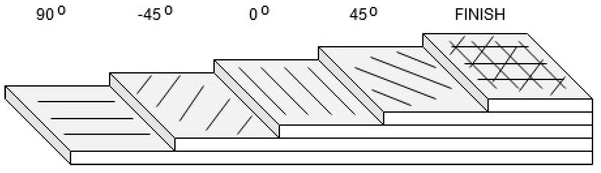
CF is classified into five types: ultra-high modulus (>450 GPa), high modulus (350–450 GPa), intermediate modulus (200–350 GPa), low modulus and high tensile (100 GPa, tensile strength > 3.0 GPa), and super high tensile modulus (modulus > 450 GPa). High-performance composites are created from the layer of the fiber sheet. These sheets have adhered together. The layer from which composite is constructed is known as a ply. Plies are a collection of layers that are piled on top of one another in carbon composite constructions as shown in
Figure 1. In order to transfer the load force, each layer is attached to the next layer. The structural stability is greatly compromised if this bond is disrupted; it is also typical for the plies orientation to shift from those directly above and below. This increases strength in a desired direction which is deemed suitable for the application. It is also preferable to have symmetrical stacked ply make up as this reduces the chances of warping during the curing process. It is, however, also common for non-symmetrical layer makeups, although extra skill is required as to ensure the structure is as intended after the curing process [
28].
During the production process, composites might develop defects as a due to improper use or poor quality. The most prevalent types of failure includes; deamination of plies, debonding of fibre matrix, cracking of the matrix and fibre breakage [
31]. Stress concentrations caused by thermal shrinking create matrix fractures. Debonding can happen when the bonding forces (physical, mechanical, or chemical) that hold the bond together are weakened.
Whereas the most common type of failure between the above stated ones is the delamination (as discussed in
Section 1). It can manifest itself in a variety of ways such as a fracture inside the resin or adhesive or reinforcement, and de-bonding of the resin from the reinforcement. Process-related material flaws may include voids or areas of high fibre content and/or high matrix content as well as fibre misalignment and/or laminate stacking problems. The composite material may eventually fracture as a result of these processes [
32].
3. Methodology
Wet lay-up and pre-preg manufacturing techniques were used to examine the performance of continuous CF laminates and the fracture point by examining samples with 4 and 7-ply. Pre-preg is when the fabric in this case carbon is pre impregnated with resin whereas with wet lay-up, each ply is coated usually by hand with resin and debulked after it is placed.
There were five of each ply variant manufactured, for a total of 20 samples. These ply variants were evaluated to compare the two; normal applications require structural parts to be both rigid and flexible depending on the region or orientation to fit the application; hence, a suggestion can be given. To better understand manufacturing failures, several production processes were examined. The continuous CF laminate utilized in the tests was made up of 2 × 2 twill weave continuous carbon fibres. The weave can be improved for such applications due to its flexibility and capacity to prevent stress concentrations when employed at an angle. To improve anisotropic strength, the first set of samples was produced using a wet lay-up manufacturing process with alternating 90° orientation [
33]. Carbon cloth was coated with 100-part epoxy resin and 30-part hardener according to technical specifications in a wet lay-up technique. Sections of the cloth were then cut and layered to achieve the necessary ply thickness. The stacks were positioned on permeated release material that was coated in PTFE glass fibre fabric, punctured release film and bleeder breather. The composite was then vacuumed for 24 h to support the expulsion of surplus resin and to ensure that the resin was evenly dispersed throughout the whole structure. In order to achieve better uniformity, temperature annealing/curing cycle has been applied for the pre-preg samples that generated CF laminates [
28].
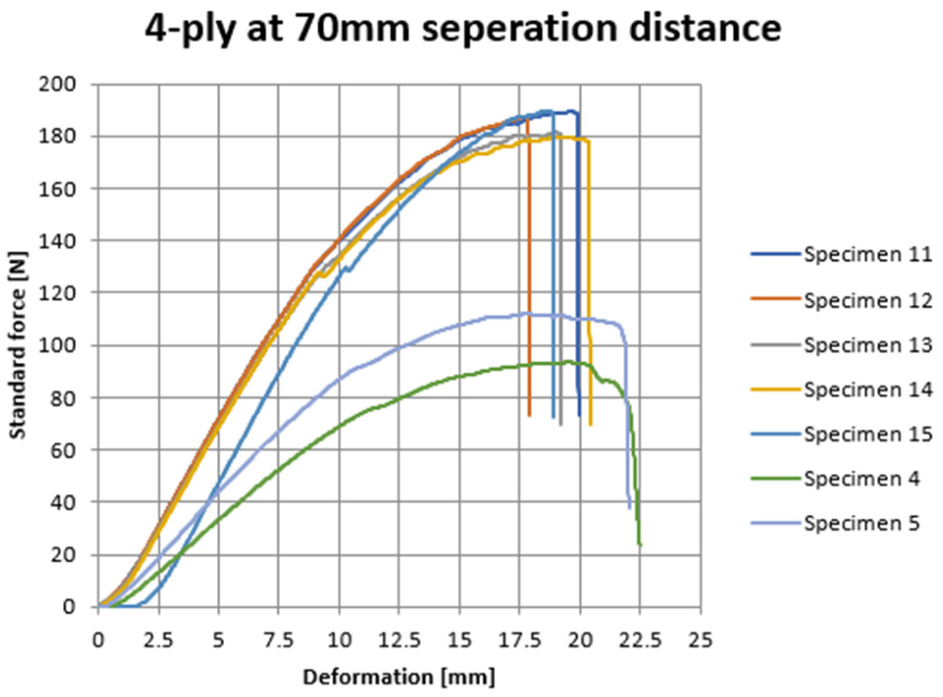
Test samples for Zwick Z010 machine were prepared by slicing composite material into suitable sample sizes of 300 × 300 mm, after the curing. Each sample was put through a three-point flexural test. It was determined that varying the separation distance would offer the best test criteria for comparing batches, while varying the strain rate would allow an examination of how stiffness vary with strain rate.
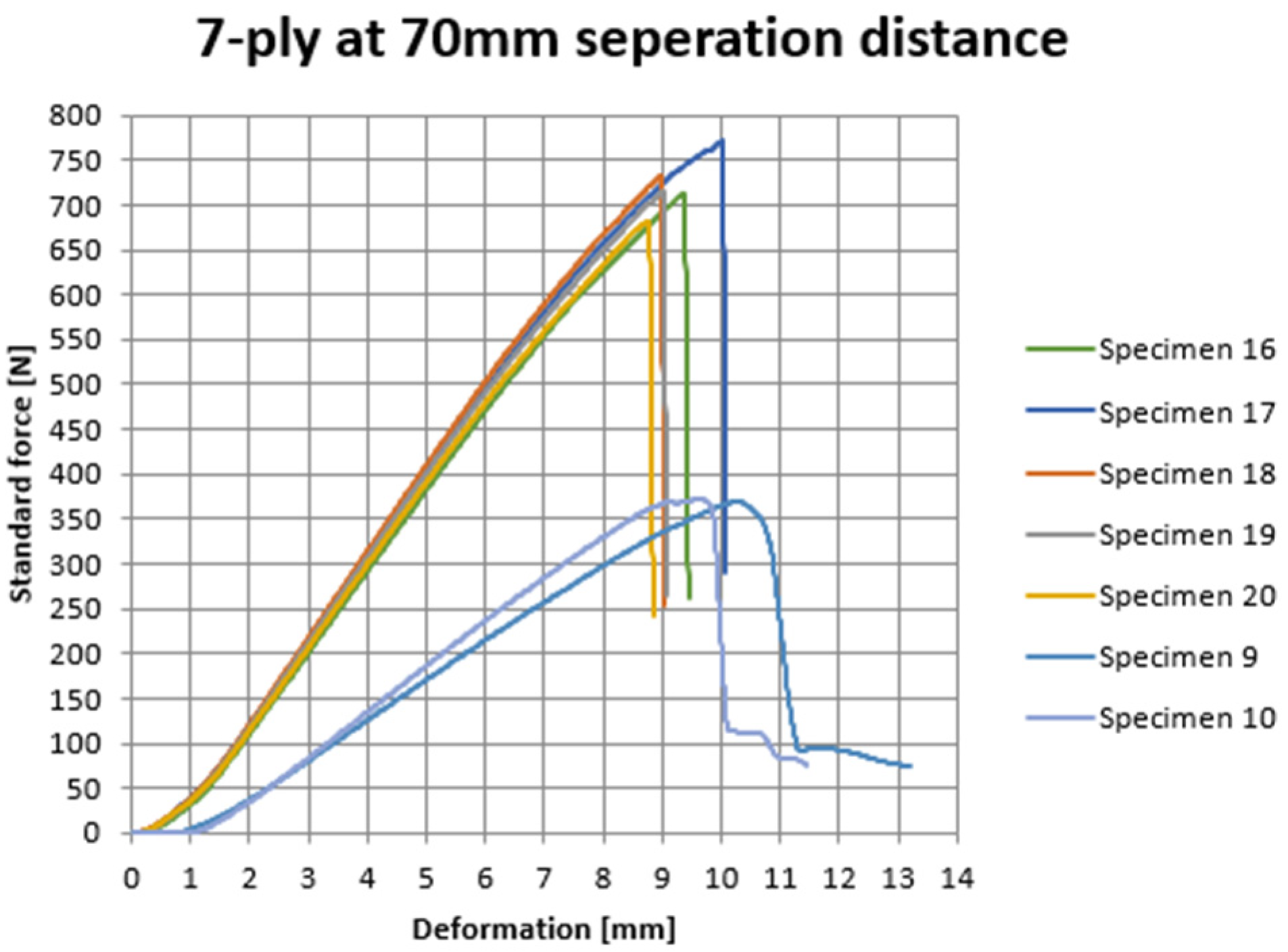
Figure 2 and
Figure 3 show the results of each test, which were completed till failure. For the 4-ply samples, the graph of force against deformation is shown in
Figure 3. For the 7-ply samples,
Figure 3 exhibits the same results.
Table 1 and
Table 2 contain the specimen number, number of plies, manufacturing technique, speed of force, and other data needed to identify the precise test parameters for individual specimens in
Figure 2 and
Figure 3 [
28].
In the three-point flexural test, the maximum separation distance for Specimens 1–3 was established at 70 mm to prevent observed specimen sliding when the sample spacing was more than this value. This distance was used to test the following specimens.
4. Discussion
Since mechanical characteristics can be used to build structures or components using predetermined materials in order to prevent unacceptable amounts of failure and/or deformation, a variety of mechanical properties must be measured and documented properly. Since the force-deformation properties of a CF composite are reliant on specimen shape, studying the stress–strain relationship will shed light on the composite’s issues.
According to expectations, the stiffness value of the CF specimens is inversely proportional to the speed with which force is applied. It has been observed that the 7-ply specimens had a far higher stiffness value than the 4-ply specimens.
Wet lay-up samples had an average flexural strength of 566.7 MPa ± 27.3 MPa, whereas pre-preg generated specimens had an average flexural strength of 680.8 MPa ± 13.4 MPa, indicating that the wet lay-up samples had a 16.7% drop in flexural strength.
This was deemed acceptable as it is very difficult to maintain a consistent resin to fabric ratio of the wet layup as the resin content is added by hand, showing how many variables there are and the difficulty of consistent repeatability in the process, even down to the single sample piece. The reduction in strength could be attributed to the lower weight across pre-preg and wet layup samples, although the reinforcement is near identical the reduction in epoxy resin matrix is reduced as seen in
Table 3.
5. Failure Scenarios
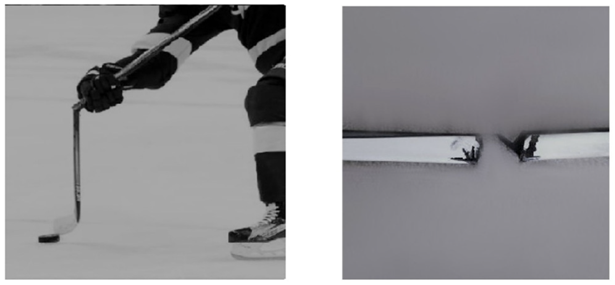
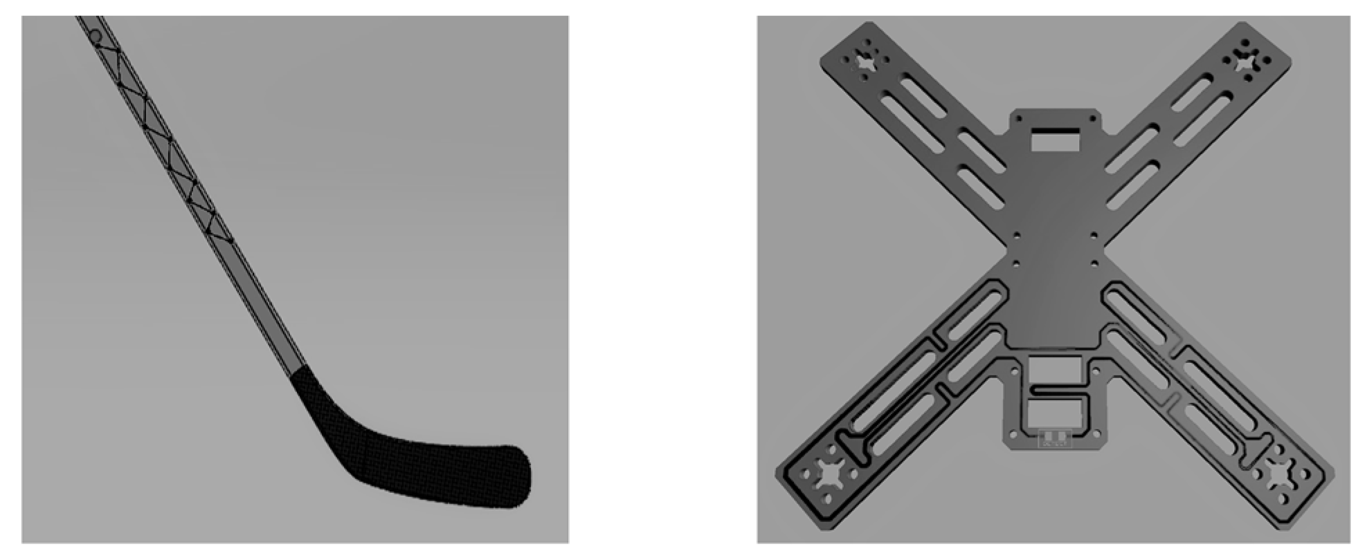
The mechanics of a composite hockey stick’s breakage is explained in an experiment performed by SmarterEveryDay [
34]. Slap shots, when the player bends the stick against the surface of the ice and then transfers the energy onto the puck, are the common cause of hockey stick fracture. CF composite samples were subjected to a three-point bend test, which replicates the mechanism that leads to fracture. In fact, the mid-point of the test replicates the hand of the player during a slap shot, when tension builds at shaft location. Fractures in hockey sticks often occur around where the player holds the stick (
Figure 4) [
35].
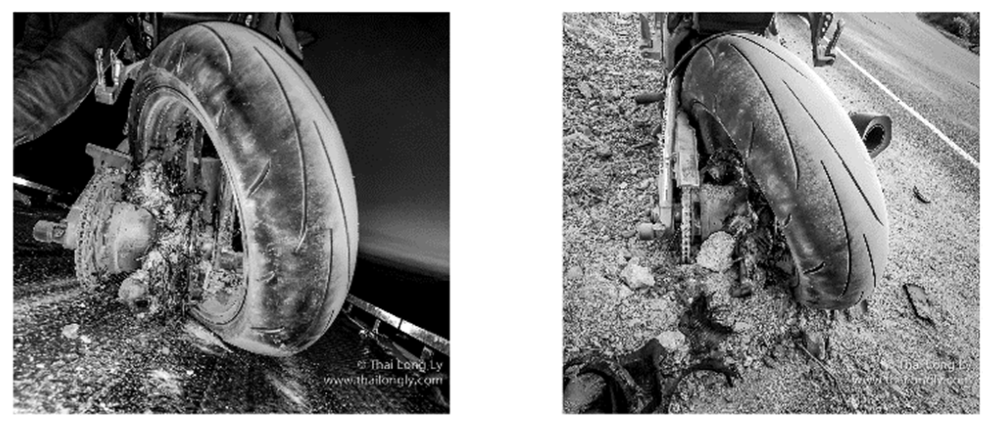
A handwritten report of a CF motorcycle wheel failure describes a potential fatal near miss when a high-power aftermarket motorcycle wheel failed. The wheel manufacturer, a relatively new producer of such products reportedly handled the reporting of the event with extreme satisfaction and the user held no responsibility to the product itself. The high-performance wheels are designed and destined for the track; in this case they were used for street rides upward of 20,000 km over 5 years on an 80 ft/lbs high powered motorcycle on weathered mountain passes. The images of the failure are seen in
Figure 5.
An application in the field of archery is CF arrows failing unexpectedly during use. A simple hand flex test and twist of the arrow before each use should be carried out but users either become complacent or are unaware of this simple test. The resulting dangers from a failure are only apparent upon the complete failure usually resulting in hand injuries.
It is difficult to determine the exact cause of CF failure at consumer level, due to the lack of reliable knowledge to its history of use. It could involve manufacturing defects or in use abuse, which could occur with or without the user’s knowledge. A common complaint within online reports and forums from consumers is that the CF products failed without warning, unlike metals, there are usually some visual indications of damage such as dents or misalignment of which the user associates with potential structural problems. CF seems to always take the user by surprise as to its failing structural properties. Arguably frequent inspection routines could reduce unexpected failings, but it seems that the majority of users do not practice this until they have in fact witnessed the potential for harm with CF products. This could be simply catalogued as a lack of user knowledge to appropriate use of such materials. As CF becomes more widespread, and costs reduce, it can be difficult to be aware that such a product is constructed of such a material. This is especially true in used sales, there is no historical evidence on the state of the product nor methods of lay man’s inspection as to the structural state other than paying specialists for such inspections. This becomes even more difficult as it is common for aluminium or stainless-steel push bike frames to have single parts made of CF. For example, an aluminium bike can have CF forks, in order to maintain its overall design aesthetics, the carbon forks are spray painted the same colour as the frame, and it can be extremely difficult for the prospective buyer to even be aware that the forks are, in fact, CF. It is highly unlikely that the user will inspect the forks as they are entirely unaware of the material inspection requirements. It is, therefore, expected that as products near there end of their life and have been passed on through a second sale, that increasing occurrences of CF accidents will increase.
6. Failure Detection
This study proposes a novel live failure detection technique for better monitoring the fracture of a hockey stick made of CF composite. The lower third of the hockey shaft can be highlighted as the most likely fracture area, due to the low position of the player’s hand during a slap shot. Thus, this area will be targeted in the design. The novel live failure detection method uses an LED or buzzer attached to a copper wire circuit inserted in the ply stack or on the inner and outer surfaces of the ply stacks. The LED/buzzer will be triggered when the hockey stick is overextended owing to the copper wire breaking [
1].
Due to composite’s structural complexity, circuit properties may be determined by a variety of parameters based on composite flex number, or the extent of flex supplied per pound of force [
36].
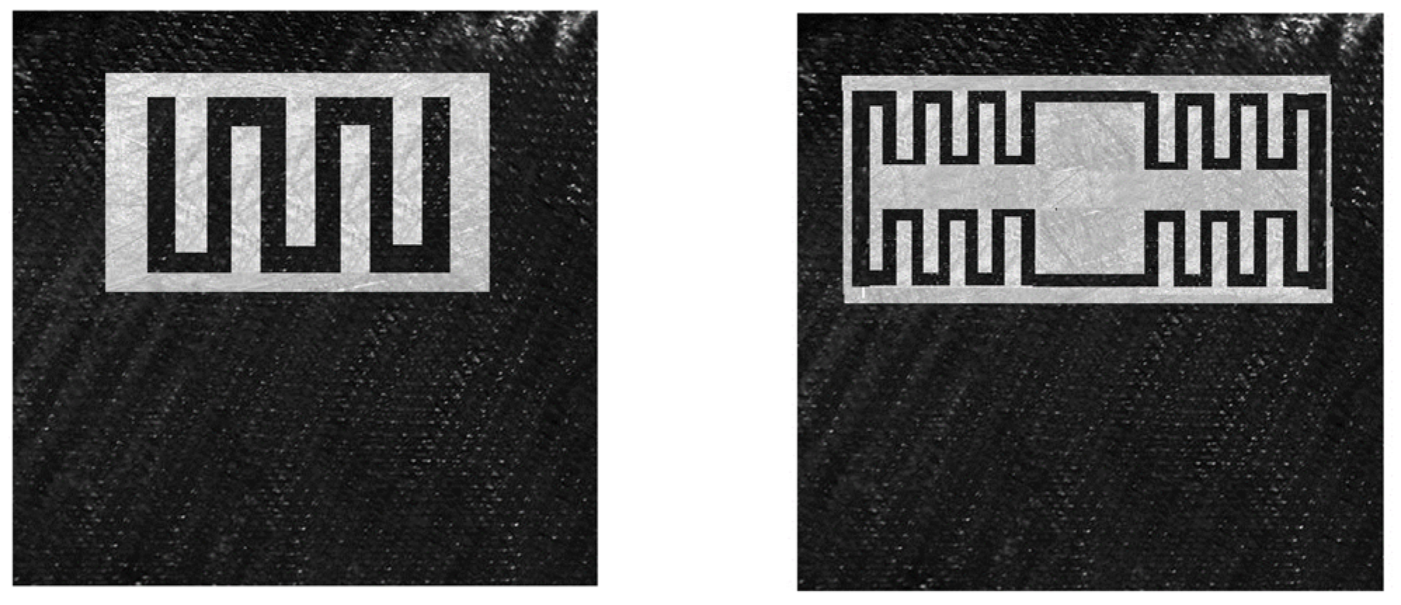
Figure 6 (left picture) depicts the notion failures monitoring system based on copper wire is depicted in
Figure 6 (left picture). The copper wire circuit is shown by the dark lines.
Similarly,
Figure 6 (right image) shows failure detection mechanism within the lower section of a drone 3.2 mm National Electrical Manufacturers Association (NEMA) flame retardant (FR) frame. Woven fiberglass fabric with an epoxy resin binder makes up this composite material. Again, the detection comprises a copper makeup on the upper layer, a simple task with printed circuit board (PCB) manufacturing processes.
Recent discoveries surrounding laser induced graphitisation (LIG) display promising results at producing graphene an allotrope of carbon arranged in a two-dimensional honeycomb lattice on pine. To produce high-quality graphene, pine wood was chosen because of its lignocellulose which is cross-linked structure, as compared to wood which has less amount of lignin complex organic polymer material. In wood, lignin is responsible for the formation of cell walls that are stiff. Similar to the polyimide (PI) method, a typical commercial carbon dioxide laser (CO
2) at ambient temperature and pressure can be used. To keep the pine from burning, argon or helium must be used to create an inert environment. Ye et al. claim that converting wood into graphene brings alternative paths for the production of LIG from materials other than polyimide [
37]. This certainly is true of potential low-cost live failure monitoring of possible wood composites with conventional readily available equipment. Interestingly, such lasers are typically accompanied by air assist nozzles that blow compressed air on the laser site when in operation to clear the debris and prevent burning under non LIG intended applications such as engraving and cutting.
A possible but as yet untested solution to requiring an inert atmosphere such as a sealed unit for production of LIG on wood would be to replace the compressed air supply with the inert gas, similar to how welders operate. This would greatly reduce the constraints required and open up graphene production on large samples, such as wooden structures. This would be beneficial to having laser produced electrically conductive patterns etched on structures in which to monitor live failure of wood composites. It would be necessary however, to ensure a basic level of protection of the laser etched graphene by such means as a suitable lacquer or finishing paint.
The inherent electrically conductive properties of CF and recent advancements in graphene production on high lignin woods offers potential interesting opportunities yet to be exploited from composites when viewed from a system engineering perspective. With electrically conductive materials in place or conductive pattens being simple to etch on surfaces, it is entirely feasible to create fundamental components seen in electronics industry within the structure of the composite.
Previous success has been achieved at pre detecting complete structural failure before the event with use of a thin enamelled copper wire embedded within carbon fibres. The success rate was approximately 50% for simple designs. This detection rate is expected to rise significantly with utilising the same principles but with conductive material with a similar Young’s modulus, obviously for CF structures this would be CF itself. However, issues over such a large surface area would be that small fracture points could go undetected as the electrical current would simply take the path of least electrical resistance. To register such small differences, the electronics would need to be significantly enhanced leading to larger more expensive failure system such as tomography. The requirements and processing power for such a system is deemed infeasible for the applications other than high cost or static applications.
By utilising an approach where an extra redundant layer is added on the inner surface of a structure, such as non-conductive/conductive reinforcement material, i.e., fibre glass/CF, it may be possible to detect non visible damage before a serious failing occurs with low level electronics and very low power consumption for its operation. Multiple methods can be taken for this approach and research is currently ongoing.
Figure 7 below shows simple layout utilising carbon fibres inherent electrical conductivity with glass fibre isolation mat.
The inherent electrically conductive properties of CF and recent advancements in graphene production on high lignin woods offer the opportunity to potentially monitor resistance changes directly on the structure of the material.
Figure 7 (left image) shows a square of CF with a layer of thin fibre glass as an electrical isolation, stacked on top of this is a simple CF pattern in which the open ends allow for simple connection to monitoring circuitry. Should the CF layer fail or become damaged the electrical properties will alter and can be flagged up by the circuitry. As the layers will be placed during the build process, they will all undergo the same curing stages and should maintain as close as possible the structural properties of the component.
Similarly,
Figure 7 (right image) shows the layout with a Wheatstone bridge configuration. Typically used with resistors to measure strain. The central conductive space would be supplied with an electrical potential and the outer voltage would be used to measure the potential. When the bridge is in balance there will be no potential difference at the output, however, changes in one of the bridges arms will result in a potential difference at the output which can be monitored by the accompanying electronics. It would be highly unlikely that all four arms of the bridge suffer similar damage in the event of damage and hence would register the change. Although this may be of little relevance in its current form, when such a setup is within the inner circumference of a tube then valuable changes in structure can be reported back. The addition due to its construction will also add extra strength to sections of interest. Research is still underway into methods for a simple low-cost solution to apply and monitor changes within composites for consumer use, in order for a simple and effective solution for end users to gauge possible approaching failures and fatigue.
7. Conclusions
Investigating the fracture point and analysing CF composite behaviour is the focus of this research. This study includes an experimental examination to look into the characteristics, as well as fresh data on the theoretical and experimental aspects of continuous CF laminates, and to broaden the list of material options for manufacturers. It also featured a mechanism for better monitoring a CF hockey stick’s fracture point.
Various novel methods are suggested of incorporated failure detection into structures as to assist in the prevention of catastrophic failures upon damage detection, potentially extending towards wood composites upon further research. It is evident that various batches of composite materials can exhibit differing overall strengths due to the difficulty in precisely regulating the processes when producing composite structures especially manually.
Previous research has shown that a like-for-like conductive material should be implemented when incorporating failure detection in terms of its Young’s modulus to allow for a better matched failure expectation as copper is malleable and typically stretches beyond that of the composite which is less than ideal. The recent advancement in LIG could provide a simple method to adding a conductive pattern to the surface of woods with high lignin content in which electrical continuity could be monitored and therefore offer damage detection opportunities. Although Balsa woods have a lower lignin content to pine it would be of particular interest in low density fields such as hobbyist, aircraft, surfboards, etc., if graphene could be produced with this wood especially due to growing concerns with environmentally friendly materials. With further research, it is expected that various low-cost methods of damage detection can be implemented across a range of structural composites with the methods presented, it serves as a stepping stone to further enhance materials with failure mechanisms as part of the structure. Composites are often chosen for the intended application and are successful of achieving the desired task, this approach is typically single minded and focuses only on the physical structure itself as to regard to shape and load carrying capabilities. If a systems engineer approach is taken, as well as a multidiscipline team view, advancements in materials may be possible to exploit much sought-after additional benefits from these currently single intent materials.


 ,
, 


